Eco Spa E1 User manual
1
The ORIGINAL Hard Cover Spa®
OWNER’S MANUAL
MODELS E1-E2-E3-E4
IMPORTANT SAFETY INSTRUCTIONS INSIDE.
READ ENTIRE MANUAL BEFORE INSTALLING SPA.
PLEASE SAVE THIS MANUAL FOR FUTURE REFERENCE.
OWNER’S RECORD
Please record the following important information here for handy reference.
MODEL #: _________
SERIAL #: _____________________________________________
DATE PURCHASED: ________________________
PRICE PAID (BEFORE TAX): $______________
DATE INSTALLED: _______________________
DEALER NAME: _______________________________________________
DEALER ADDRESS: _____________________________________________
CITY ________________________STATE____ ZIP_________
DEALER TELEPHONE: _____________________________________
March 2017
By: Fusion Pacific

2
FACTORY LIMITED WARRANTY
This warranty begins on date of delivery and it extends to the original purchaser of any model ECO SPA manufactured
January 2015 or later. If your ECO SPA develops a defect that is covered under the terms of this warranty, it will be
repaired by Fusion Pacific Inc. (FPI) or its authorized dealer. The original owner must register their product through our
website at www.ecospas.com or mail their warranty card within thirty (30) days from purchase or taking delivery,
whichever comes first, to activate this warranty.
LIFETIME STRUCTURAL
The structural integrity of the ECO SPA is warranted to be free of defects for lifetime. Should the ECO SPA structure
develop a defect and not hold water within the warranty period, it will be repaired or replaced (at FPI’s discretion) by
FPI. Any related shipping charges are the responsibility of the Spa owner.
LIFETIME ECO-HARDCOVER WITH ATTACHED ARMS
The ECO-HARDCOVER WITH ATTACHED ARMS is warranted for Lifetime to be free from defect in materials and
workmanship. Clamps are provided and should be used to better trap heat and keep the cover true to the spa.
3 YEARS PLUMBING
ECO SPA warranties all plumbing parts to be free from defects in material and workmanship for a period of three (3)
years from original date of purchase. This limited warranty specifically covers leaks from wall fittings jet fittings, internal
plumbing, internal glue joints, drains, air controls, diverter valve and light lens. Jet damage caused by chemical extremes
and/or chemical imbalances in the water is not covered by this warranty.
3 YEARS COMPONENTS
ECO SPA components, including top side control, spa control pack, pump, pillows, heater and, if so equipped, ozone unit
and LED lighting systems, are warranted to be free of defects or leaks for a period of three (3) years from the OEM date
of manufacturing. Defective components within three (3) years will be replaced or repaired (at FPI’s discretion) by FPI.
Component damage caused by chemical extremes and/or chemical imbalances in the water is not covered by this
warranty.
3 YEARS LABOR
ECO SPA will provide a 3-year labor warranty. Refer to your dealer for warranty service.
DISCLAIMER
FPI assumes no liability or responsibility for incidental, consequential or other damage including, but not limited to,
removal of a deck or other custom fixture(s), transportation or shipping charges, telephone charges, rental of a like
product during the time warranty service is being performed, travel, loss or damage to personal property and loss of
revenue, use, time or inconvenience resulting from the loss of use of any ECO SPA covered by this warranty, as
applicable by state laws. This warranty does not cover any spa that has been subject to misuse, neglect, negligence,
accident, civil disturbance, acts of nature or that has been operated in a way contrary to the recommended operating
instructions or that has not been installed as specified in the ECO SPA Owner’s operating manual; this warranty does not
cover any Spa that has been modified or altered, except with parts or options that are authorized by FPI and installed
according to recommended installation instructions, This warranty also does not cover any problems caused by improper
water chemistry, improper PH balance, improper wiring, use of extension cords or failure to provide an isolated electrical
service. Not covered are electrical issues or other problems which are not from defects in manufacturing. This warranty
does not cover any ECO SPA that is being used for commercial purposes or has been operated extensively on display or
that has been left uncovered or without water for long periods of time.

3
TABLE OF CONTENTS
GENERAL INFORMATION
COVER, OWNER’S RECORD …………………………………………………………………………………………….. PAGE 1
FACTORY LIMITED WARRANTY ……………………………………………………………………………………. PAGE 2
TABLE OF CONTENTS …………………………………………………………………………………………….…….…. PAGE 3
THANK YOU, HELPFUL HINTS …………………………………………………………….……………………….…. PAGE 4
IMPORTANT SAFETY INSTRUCTIONS …………………………………………………..……….…………. PAGES 5 – 7
INSTALLATION GUIDE ……….…………………………………….………………………………… PAGES 8 - 9
SETTING UP AND FILLING YOUR NEW ECO SPA ………………………………….………….……….…… PAGE 10
CARE AND MAINTENANCE INSTRUCTIONS ……………………………………………………….… PAGES 11 - 12
AUTOMATED FEATURE FUNCTIONS
POWER UP/BOOT SEQUENCE …………………………………………………..………….…….….…….……... PAGE 13
AUTOMATIC DRY-FIRE PROTECTION ..………………………….……………………………………..…….… PAGE 13
AUTOMATIC WATER TEMPERATURE REGULATION …………………………………………………….… PAGE 13
AUTOMATIC HEATER ELEMENT COOLDOWN …………………………………………..……………………PAGE 13
AUTOMATIC SMART WINTER MODE …………………………………………………….……………………… PAGE 14
FILTER CYCLE …………………………………………………………………………………………………………..…… PAGE 14
ECONOMY MODE ……………………………………………………………………………………………….……….. PAGE 14
UNDERSTANDING & USING YOUR ECO SPA TOPSIDE CONTROLLER
WHAT THE ICONS IN THE WINDOW MEAN …………………………………………….………………..….. PAGE 15
SPA FUNCTIONS –OFF MODE ……………………………………………………………………..…………..…… PAGE 15
JETS, LIGHT, WARM & COOL BUTTONS …………………………………………………………....…. PAGES 15 - 16
PROGRAMMING –SETTING THE CLOCK ………………………………………………………….………….... PAGE 16
PROGRAMMING –SETTING THE FILTER CYCLE ………………………………………….………….……... PAGE 17
PROGRAMMING –SETTING ECONOMY MODE …………………………………………….………..……. PAGE 17
PROGRAMMING –SETTING TEMPERATURE UNITS ………………………………………………..……. PAGE 17
JET, COMPONENT AND EQUIPMENT OPERATING INSTRUCTIONS
JET OPERATION –MASSAGE JETS ………………………………………………………..…………………….... PAGE 18
AIR CONTROLS …………………………………………………………………………………..………………….…..... PAGE 18
DIVERTER VALVE ………………………………………………………………………….…………………………….... PAGE 19
OZONE JET ……………………………………………………………………………..………………………………….... PAGE 19
SUCTION FITTINGS ……………………………………………………………………………………………………….. PAGE 19
LED LIGHT ………………………………………………………………………………………………………………….... PAGE 19
TROUBLESHOOTING ……………………………….…………………………………………….………….…. PAGES 20 - 22
LOCATIONS OF CONTROLS, JETS & OTHER COMPONENTS
MODEL E1 ………………………………………………………………………………………………………………….… PAGE 23
MODEL E2 ………………………………………………………………………………………………………………….… PAGE 24
MODEL E3 ………………………………………………………………………………………………………………….… PAGE 25
MODEL E4 ………………………………………………………………………………………..………….…………….… PAGE 26
WIRING FOR 110/220 VOLT OPERATION ……..……………………………………………………..……… PAGE 27
BREAKER SETTING ………………………………………..…....……………………………………………....……… PAGE 27
MAINTENANCE LOG ………..…………………………………………..……………………..………….…………… PAGE 28
WARRANTY ACTIVATION CARD ………………………………………………………………………………… PAGE 29

4
THANK YOU!
Congratulations On Your Decision
To Purchase An
Easy-To-Operate And Easy-To-Maintain
ECO SPAsare built with simplicity of operation and easy maintenance in mind.
ECO SPA uses superior quality materials and top-of-the-line components and
controls to provide you with as trouble-free a hot tub experience as possible.
Side panel removal allows easy access to all interior ECO SPA plumbing and
equipment for easy maintenance or repair.
Refer to the diagrams found on pages 23 - 26 to identify the locations of the
components of your particular model ECO SPA.
Most service calls can be handled over the phone with your dealer.
Original spare or replacement ECO SPA parts are available by contacting your
dealer. Please refer to the Owner’s Record information that you recorded on the cover
of this manual to assist your dealer in determining your needs.
HELPFUL HINTS
The covers and Air Controls must be closed for the ECO SPA to heat up efficiently.
Heating time can vary depending on ambient air temperature, but generally if operating
on 110 Volts your ECO SPA will heat after fill-up at the rate of approximately 1.5° F
per hour. If the spa is operating at 220 Volts heating time will improve considerably to a
rate of approximately 3 ° - 6 ° F per hour depending on the model’s size & water volume.
While heating, condensation may develop and pool in various locations, especially
underneath the body of the spa and on the undersides of the spa’s covers which may
drip down the sides of the spa when the covers are opened. This accumulated
condensation can cause you to believe that the spa is leaking, but these seemingly
apparent leaks should be observed for a few days with the ECO SPA not in use
before proceeding with further investigation.
All Jets should be wide open to provide better water circulation for proper heating and
filtration when your ECO SPA is not in use.

5
IMPORTANT SAFETY INSTRUCTIONS
READ AND FOLLOW ALL INSTRUCTIONS
WARNING
Connect to a grounded, Grounding Type Receptacle Only.
To reduce the risk of electric shock, replace damaged cord immediately.
Do not bury the cord.
DANGER
To reduce the risk of injury to persons, do not remove Suction Fittings.
TO REDUCE THE RISK OF INJURY:
The water in the spa or hot tub should never exceed 40° C (104° F). Water temperatures
between 38° C (100° F) and 40° C (104° F) are considered safe for a healthy adult. Lower
water temperatures are recommended for extended use (exceeding 15-20 minutes) and
for younger children.
Since excessive water temperatures have a high potential for causing fetal damage, during
the early months of pregnancy, pregnant or possibly pregnant women should limit spa or
hot tub temperatures to 38° C (100° F).
Before entering a spa or hot tub, the user should measure the water temperature with an
accurate thermometer since the tolerance of temperature regulating devises may vary as
much as plus or minus 3° C (5° F).
The use of alcohol, drugs or medication before or during spa or hot tub use may lead to
unconsciousness with the possibility of drowning.
Persons suffering from obesity or with a medical history of heart disease low or high blood
pressure, circulatory system problems, or diabetes should consult a physician before using a
spa or hot tub.
Persons using medication should consult a physician before using a spa or hot tub since
some medication may induce drowsiness while other medication may affect heart rate,
blood pressure, and circulation.
WARNING
The use of Alcohol, Drugs or medication can greatly increase the risk of fatal hyperthermia.
Hyperthermia occurs when the internal temperature of the body reaches a level several
degrees above the normal body temp plus or minus temperature of 98.6° F. The symptoms of
hyperthermia include dizziness, fainting, drowsiness, lethargy and an increase in the internal
body temperature. The affects of hyperthermia include (1) unawareness of impending hazard,
(2) Failure to perceive heat, (3) Failure for the need to exit the Spa, (4) Physical inability to exit
Spa, (5) Fetal damage to pregnant women, and (6) Unconsciousness resulting in a danger of
drowning.

6
IMPORTANT SAFETY INSTRUCTIONS
READ AND FOLLOW ALL INSTRUCTIONS
DANGER: RISK OF ELECTRICAL SHOCK
Do not permit any electric appliance such as a light, telephone, radio, or
television within 5 feet of a spa or hot tub.
WARNING: CHILDREN SHOULD NOT USE A SPA OR HOT TUB WITHOUT ADULT SUPERVISION.
AVERTISSEMENT: NE PAS LAISSER LES ENFANTS UTILISER UNE CUVE DE RELAXATION SANS
SURVEILLANCE.
WARNING: DO NOT USE A SPA OR HOT TUB UNLESS ALL SUCTION GUARDS ARE INSTALLED TO
PREVENT BODY AND HAIR ENTRAPMENT.
AVERTISSEMENT: POUR EVITER QUE LES CHEVEUX OU UNE PARTE DU CORPS PUISSENT ETRE
ASPIRES, NE PAS UTILISER UNE CUVE DE RELAXATION SI LES GRILLES DE PRISE D’ASPIRATION NE
SONT PAS TOUTES EN PLACE.
WARNING: PEOPLE USING MEDICATIONS AND/OR HAVING ADVERSE MEDICAL HISTORY
SHOULD CONSULT A PHYSICIAN BEFORE USING A SPA OR HOT TUB.
TAVERTISSEMENT: LES PERSONNES QUI PRENNENT DES MEDICAMENTS OU ONT DES
PROBLEMES DE SANTE DEVRAIENT CONSULTER UN MEDECIN AVANT D’UTILISER UNE CUVE DE
RELAXATION.
WARNING: PEOPLE WITH INFECTIOUS DISEASES SHOULD NOT USE A SPA OR HOT TUB.
AVERTISSEMENT: LES PERSONNES ATTEINES DE MALADIES INFECTIEUSES NE DEVRAIENT PAS
UTILISER UNE CUVE DE RELAXATION.
WARNING: TO AVOID INJURY EXERCISE CARE WHEN ENTERING OR EXITING A SPA OR HOT
TUB.
AVERTISSEMENT: POUR EVITER DES BLESSURES, USER DE PRUDENCE EN ENTRANT DANS UNE
CUVE DE RELAXATION ET E SORANT.
WARNING: DO NOT USE DRUGS OR ALCOHOL BEFORE OR DURING THE USE OF A SPA OR HOT
TUB TO AVOID UNCONSCIOUSNESS AND POSSIBLE DROWNING
AVERTISSEMENT: POUR EVITER L’EVANOUISSEMENT ET LA NOYADE EVENTUELLE, NE PRENDE
NI DROGUE NI ALCOOL AVANT D’UTILISER UNE CUVE DE RELAXATION NI QUAND ON S’Y
TROUVE.

7
IMPORTANT SAFETY INSTRUCTIONS
READ AND FOLLOW ALL INSTRUCTIONS
WARNING: PREGNANT OR POSSIBLY PREGNANT WOMEN SHOULD CONSULT A PHYSICIAN
BEFORE USING A SPA OR HOT TUB.
AVERTISSEMENT: LES FEMMES ENCEINTES, QUE LEUR GROSSESSE SOIT CONFIRMEE OU NON,
DEVRAIENT CONSULTER UN MEDECIN AVANT D’UTILISER UNE CUVE DE RELAXATION.
WARNING: WATER TEMPERATURE IN EXCESS OF 40° C (104° F) MAY BE INJURIOUS TO YOUR
HEALTH.
AVERTISSEMENT: IL PEUT ETRE DANGEREUX POUR LA SANTE DE SE PLONGER DANS DE L’EAU A
PLUS 40° C (104°F).
WARNING: BEFORE ENTERING A SPA OR HOT TUB MEASURE THE WATER TEMPERATURE
WITH AN ACCURATE THERMOMETER.
AVERTISSEMENT: AVANT D’UTILISER ONE CUVE DE RELAXATION MESURE LA TEMPERATURE DE
L’EAU A L’AIDE D’UN THERMOMETRE PRECIS.
WARNING: DO NOT USE A SPA OR HOT TUB IMMEDIATELY FOLLOWING STRENUOUS
EXERCISE.
AVERTISSMENT: NE PAS UTILISER ONE CUVE DE RELAXATION IMMDIATEMENT APRES UN
EXERCISE FATIGANT.
WARNING: PROLONGED IMMERSION IN A SPA OR HOT TUB MAY BE INJURIOUS TO YOUR
HEALTH.
AVERTISSMENT: L’UTILISATION PROLONGEE D’UNE CUVE DE RELAXATION PEUT ETRE
DENGEREUSE POUR LA SANTE.
WARNING: DO NOT PERMIT ELECTRIC APPLIANCES (SUCH AS A LIGHT, TELEPHONE, RADIO,
TELEVISION, ETC.) WITHIN 1.5 M OF THIS SPA OR HOT TUB.
AVERTISSMENT: NE PAS PLACER D’APPAREIL ELECTRIQUE (LUMINARE, TELEPHONE, RADIO,
TELEVISEUR, ETC.) A MOINS DE 1.5 M DE CETTE CUVE DE RELAXATION.
CAUTION: MAINTAIN WATER CHEMISTRY IN ACCORDANCE WITH THE CHEMICAL
MANUFACTURER’S INSTRUCTIONS.
ATTENTION: LA TENEUR DE LEAU EN MATIERS DISSOUTES DOIT ETRE CONFORME AUX DIRECTIVES DU
FABRICANT DE LES CHIMIQUES.
8
INSTALLATION GUIDE
Please Read and Understand All Instructions Before Operating Your
SELECTING THE INSTALLATION LOCATION
Your new ECO SPA is completely self-contained. It can be set up on a patio, deck, or
indoors with special consideration.
Your ECO SPA must be installed on a relatively smooth, solid, flat and level surface
that will support 3,000 pounds. Concrete, bricks, pavers or wood deck are acceptable
permanent surfaces. The majority of the weight of the spa is placed under the foot well
area of the spa. This area must be firmly supported at all times.
DO NOT USE SHIMS, WEDGES, OR OTHER TYPES OF LEVELING DEVICES TO LEVEL THE SPA
It is critical that you do not use shims, wedges or other types of leveling devices to level
the spa. 100% CONTACT OF THE SPA’S FLOOR WITH THE SITE IS NECESSARY TO
PREVENT LONG TERM DISTORTION OF THE SPA SHELL (BODY) WHICH COULD AFFECT
THE FIT OF THE COVERS. IMPROPER INSTALLATION IN THIS MANNER MAY VOID YOUR
WARRANTY.
Do not place your ECO SPA in an area where the water will puddle around it.
Drainage of water away from the spa’s power cord and electrical equipment
compartment is necessary.
Place your ECO SPA away from areas where debris or dirt may be tracked into it.
Your ECO SPA should not be placed near or below electrical or telephone cables.
Consider privacy and wind shielding. A sheltered environment can result in lower
operating and maintenance costs.
Leave a minimum of 24 inches of open space at each end of the spa to ensure that the
cover will open and close properly.
Leave adequate space around the spa to allow full access to the Control System and
Pump access panels, Drain Cover and Power Cord cover plates. (See pages 23 - 26 of this
manual for a diagram of where these are located on your particular ECO SPA
model).
The proper site of your ECO SPA should be an area that is Not Accessible to
Children. Security fencing or Pool Yard gates should be in place to separate Children
from the Spa.

9
If you are going to operate your ECO SPA at 110 Volts your ECO SPA draws a
maximum of 12 Amps operating at 110 Volts. A GFCI power cord is supplied with all 110
Volt models.
Locate the round plate labeled POWER CORD on the outside bottom corner of the rear
side of the spa, remove it and pull out the electrical cord with the attached GFCI unit
that is located behind this plate. Assure that the cord will reach a grounded wall outlet
of a 110 Volt 15 amp circuit without using an extension cord. IF YOU MUST USE AN
EXTENSION CORD, IT MUST BE GROUNDED (3-PRONG), AT LEAST 10 GAUGE AND AS
SHORT AS POSSIBLE. USING AN INFERIOR EXTENSION CORD WILL LIKELY CAUSE A
VOLTAGE DROP WHICH WILL CAUSE THE SPA’S CONTROLS TO MALFUNCTION AND
COULD DAMAGE COMPONENTS. If there is not a 110 Volt 15 Amp grounded outlet close
enough to the spa to do so you may want to consider contacting a Licensed Electrician to
supply power to the Spa in a proper manner.
Do not plug the power cord into the outlet until the spa is completely filled with water
to the proper water level.
If you are going to operate your spa at 220 Volts, you must hire a certified electrician to
install a 220V, 50 Amp GFCI breaker and to connect the wiring to your spa per all local
and national codes. (See page 27 of this manual for instructions on how to convert your
ECO SPA from 110V to 220V operation). Ensure that the 220V breaker is
disconnected until the spa is completely filled with water to the proper level.
SPECIAL CONSIDERATIONS FOR INDOOR INSTALLATION
Install your spa on water resistant, non-slip floor, preferably
with a drain to remove the water that is splashed from the
spa. Do not install on carpet or other material that will be
damaged by moisture.
Take into consideration the room humidity which will exist
due to high temperatures. Providing natural or forced
ventilation in the room will help maintain comfort and
minimize moisture damage to the surrounding environment.
Indoor second story installation above finished living space
should be avoided due to the possibility of water and
humidity damage.
Allow full access to the spa equipment for service.

10
SETTING UP AND FILLING YOUR NEW
See Pages 23 - 26 for Model E1-E2-E3-E4
Locations of Jets, Components & Equipment
1. Ensure that your ECO SPA’s electrical power cord is NOT plugged in or that power to
the spa is turned OFF. Do not turn on power to the spa until it is full to the proper water
level.
2. Check that your ECO SPA drain valve (located behind the spa’s DRAIN COVER plate)
is closed and capped securely so as to prevent leaking.
3. Connect a Pre-Filter to your standard garden hose to ensure that you start out with
cleaner water.
4. Open the spa covers, remove the filter cover and unscrew and remove the filter
cartridges.
5. Make sure that the spa’s 2 Air Control knobs are in the OPEN position and that the
Diverter Valve is pointed to center.
6. Turn all Jets counter-clockwise to the full OPEN position. Doing so will minimize the
amount of air in the water lines to help avoid causing a potential ‘airlock’ and will make
priming the pump easier.
7. Fill your ECO SPA to an approximate water level of 2" above the top of the highest
jet. Once the spa is filled to this level, power can then be supplied to your ECO SPA.
8. Carefully re-install the 2 filter cartridges into their sockets and re-install the Filter Cover.
9. Plug in the GFCI unit of the 110 Volt power cord and depress the reset button on it or, if
applicable, connect the power for 220 Volt operation.
10. Once the power is on, the pump should come on at High Speed for 1 minute to purge air
from the water lines and verify adequate water flow and then it will shift down to Low
speed. Meanwhile, the window of the Topside Control panel will display a series of
codes, then a series of dashes ( ----) and finally settle on toggling between displaying
Time and Temperature.
11. The and icons will be flashing in the window of Topside Control Panel indicating
the spa is taking a water temperature reading and may be calling for heat.
12. The icon will then show solid in the window of Topside Control Panel as the heater
will automatically begin heating to the Temperature Set Point you programmed on your
Topside Control Panel. (See ECO SPA Topside Controller Instructions on pages 15 -
17.)
13. Once the water temperature has reached at least 80°F (27°C) so that chemicals can
dissolve properly you can now test and balance the pH Level of your water and sanitize
it per the chemistry guidelines supplied by your dealer.
14. ECO SPA is not responsible for damage to the spa from improper or excessive
chemical use. ECO SPA recommends that you read and understand the spa
chemistry guidelines supplied by your dealer or consult with a local spa supply retailer.
11
CARE AND MAINTENANCE INSTRUCTIONS
HARD COVERS & SPA SURFACES
When not in use please keep your ECO SPA hard covers clamped down at all times,
especially in extreme weather conditions. Consistent use of the clamps will help maintain the fit
of the covers to the spa.
CLEANING YOUR ECO SPA
The high-grade resin from which your ECO SPA is constructed can easily be cleaned with a
vinegar and water solution.
CLEANING THE FILTER CARTRIDGES
The filter cartridges should be rinsed and cleaned at least once every month or more frequently
for high bather loads. You may wish to also soak excessively dirty cartridges overnight in filter
cartridge cleaner solution; if you do, be sure to rinse them out thoroughly before re-installing.
Disconnect power to your ECO SPA.
Remove the filter cover.
Remove the filter cartridges from their sockets by unscrewing them (counter clockwise).
Attach a filter cleaner nozzle to your garden hose and rinse dirt and debris from the
cartridge pleats thoroughly.
Allow the filter cartridges to air dry completely before reinstalling them. Drying allows
the fabric of the cartridges to expand properly in order to filter effectively.
Replace the filter cartridges, aligning them with care to not ‘cross-thread’ them in their
sockets. Do not tighten them excessively.
Reinstall the Filter Cover.
Power to your ECO SPA can then be turned back on.
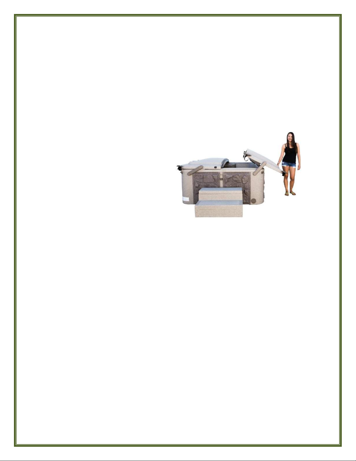
It is best and easiest to pull the
covers open and down from the ends
of the spa using the handles as this
helps to maintain even weight
balance.
Lifting the covers by one side or the
other instead of pulling them open in
this manner puts undue stress on the
lifter arm(s) due to the unbalanced
weight.
12
DRAINING YOUR SPA
Drain and refill your ECO SPA with fresh water to the recommended level as necessary.
Depending on the frequency and length of your spa sessions and water quality management,
you may have to do so more or less frequently.
Hint: once water chemistry becomes difficult to control and/or maintain properly, the water
needs to be changed.
Unplug or disconnect the ECO SPA’s electrical power supply. The ECO SPA must
remain unplugged until re-filled with water.
Rotate the Air Controls to the fully OPEN position.
Remove the cap from the ECO SPA's Drain valve and connect it to a standard garden
hose. Place the opposite end of the garden hose in the desired drainage area and twist
the knob on the ECO SPA’s Drain Valve to open it and commence draining.
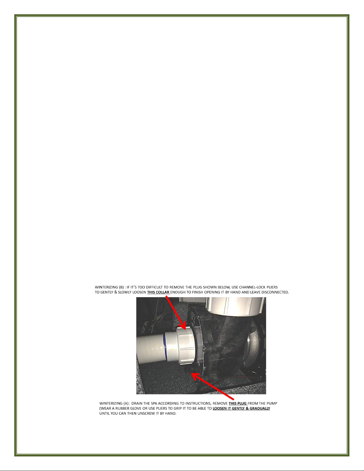
WINTERIZING
If your ECO SPA is to be transported or stored in temperatures 32º F (0º C) or lower, it is
critical that your ECO SPA be fully winterized.
The ECO SPA must be fully drained and emptied. (See DRAINING YOUR SPA, above)
1. The Drain Valve must remain in the open position with the Drain Valve Cap removed
and stored.
2. The Filter Cartridges must be removed, dried and stored.
3. Unscrew and remove the plug located at the bottom of the pump housing. The pump is
located behind the panel with the louvered vent. (For the location of this panel on your
spa, see the diagram of your model on pages 23 -26).
13
AUTOMATED FEATURE FUNCTIONS
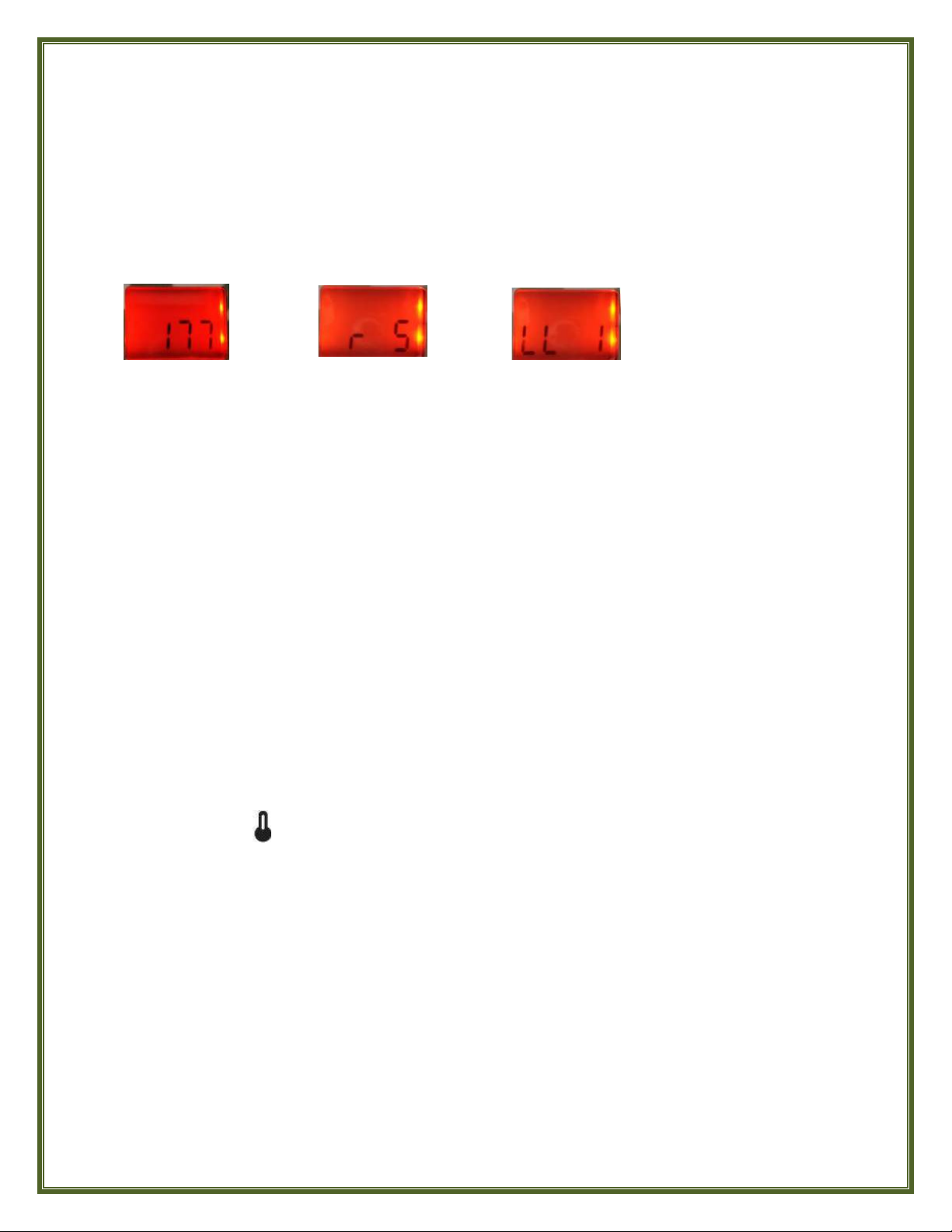
POWER UP/BOOT UP DISPLAY SEQUENCE
Once power to your Eco Spa has been turned on, each of the following parameters initially
appears in the Topside Controller Display for 2 seconds in this sequence:
AUTOMATIC DRY-FIRE PROTECTION
After the above sequence of parameters has appeared at power up, the Topside Controller’s
Display will show “- - -“ and the pump starts on Low Speed for 2 minutes as the Eco Spa’s
System performs a flow check to verify a proper water flow rate to the heater of 18 GPM to
protect the heater from firing prematurely (“dry fire”). Once proper water flow rate is verified,
the current water temperature will then be shown in the display, toggling with the current
time.
AUTOMATIC WATER TEMPERATURE REGULATION
Every 15 to 90 minutes the pump will come on at Low Speed to ensure accurate water
temperature as well as to avoid heater activation in “dry fire” conditions (inadequate or absent
water flow through the heater element). Over time, the system will “learn’ your spa’s water
temperature variations and thus at what time interval it needs to check and adjust it.
After verifying water flow, pump activation on Low Speed and taking a water temperature
reading, if the water temperature has fallen below the Set Point, the system automatically
turns the heater on to reach and maintain water temperature at Set Point. Once the water
temperature has reached the Set Point value plus 0.8° F the heater is turned off.
The Set Point icon flashes when taking water temperature reading. To override this mode
and immediately turn on the heater simply press the WARM button.
AUTOMATIC HEATER ELEMENT COOLDOWN
If the Heater has been On, the pump will continue to run on Low speed for 2 minutes to cool
the heater element and help prolong its useful life. If the water temperature is below the
desired set point, the pump will stay on Low speed to operate the heater until the desired
temperature set point has been reached, and then run an additional 2 minutes to cool down
the heater element.
Software Number
Software Revision
Low- Level Selection

14
AUTOMATIC SMART WINTER MODE
The indicator appears in the display window when freezing temperature is detected and
flashes when the pump is active.
FILTER CYCLE
The FILTER CYCLE is composed of the following parameters: Filter Start Time (FS), Filter
Duration (Fd) and Filter Frequency (FF). A FILTER CYCLE consists of starting the pump on High
speed for 1 minute to purge possible air bubbles from the water lines and then running the
pump on Low speed for the remainder of the filter cycle duration, activating the Ozone
Generator, if so equipped, and introducing Ozone into the water supply via the Ozone Jet to aid
in sanitizing.
Factory Preset Defaults for the Filter Cycle are: Start Time: 12PM; Duration: 2 Hours; Frequency:
2 times per 24 Hours.
The icon shows solid in the display window when the Filter Cycle is active and flashes when
the Filter Cycle cannot activate or is suspended because the Jets are not on at Low speed.
Also, when your spa is in an active Filter Cycle you can suspend the Filter Cycle for 20 minutes
by pressing any button on the Topside Control panel. The icon will show flashing at this time
and again show solid once the Filter Cycle has resumed activity.
ECONOMY MODE
The ECONOMY MODE is composed of the following parameters: Economy Program (EP),
Economy Start Time (ES) and Economy Duration (Ed).
When the ECONOMY MODE is active, the display will toggle between the “Eco” message, the
current time, and the current water temperature. Factory preset default for the Economy Mode
is: EP, “0” (Disabled). When disabled, the Economy Start Time and Economy Duration settings
are irrelevant.
Our Smart Winter Mode function is preset at the factory to automatically
protect your spa from the cold by turning on the pump several times a day
to prevent water from freezing in the spa’s plumbing system. You do not
have to program this function and cannot alter it.
The ECONOMY MODE allows you to conserve energy during a certain period of the
day or over a number of days by minimizing operation of the Heater by temporarily
reducing the temperature set point of the spa by 20 °F (11 °C) during this
programmed cycle.
15
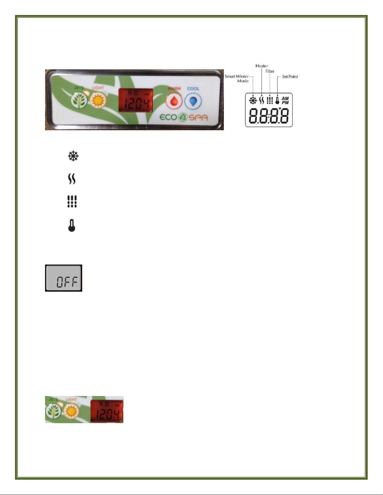
UNDERSTANDING & USING YOUR ECO SPA TOPSIDE CONTROLLER
What The Icons In The Window Mean
Smart Winter Mode: appears only when the spa has automatically activated its
Smart Winter Mode.
Heater: Flashes when taking a reading of the current water temperature or if calling
for heat. Shows solid when the heater is on.
Filter Cycle: Shows solid when Filter Cycle is active. Flashes when Filter Cycle cannot
activate or is suspended because the Jets are not on at Low Speed.
Set Point: Flashes when reading the spa’s current water temperature; shows solid
when displaying the desired water Temperature Set Point
SPA FUNCTIONS
OFF Mode
Press & hold the JETS button for 5 seconds to enable the OFF Mode. Once the OFF Mode is
active, the display will toggle between the “OFF” message, the Clock and the current Water
Temperature. The spa light will flash for a few seconds before the end of the 30 minutes to warn
you that the system is about to resume its normal operation.
Press the JETS button again once to exit the OFF Mode and restart the system before the
expiration of the OFF Mode’s 30 minute delay. When the system resumes its normal operation,
the display shows “ON” for 3 seconds, then resumes toggling between the Clock and current
Water Temperature.
JETS Button
The OFF Mode allows you to temporarily stop all outputs including automatic
functions such as Filter cycle, Heat request, Economy and Smart Winter mode for
30 minutes to perform quick spa maintenance without having to disconnect the
electrical power to your spa.
Press the JETS button ONCE to turn Pump on at LOW Speed. The
indicator light will be flashing red to indicate Low Speed. Press the JETS
Button a SECOND time to switch the pump to HIGH Speed. The indicator
light adjacent to the button will be lit solid red to indicate High Speed.
Press the JETS Button a THIRD time to turn the pump OFF.
NOTE: A built-in timer automatically turns pump Off after 20 minutes of continuous operation to
conserve energy as well as to safeguard against the spa possibly having been left operating unattended.
Simply press the JETS button once again to resume operation.
16
LIGHT Button
Press the LIGHT button a second time to turn the light Off. Repeat this on/off operation to
change the light’s various colors. A built-in timer automatically turns light off after 2 hours of
continuous use to conserve energy.
WARM & COOL Buttons
(The "Set Point" icon showing solid in the display at this time indicates that the display shows the
desired temperature, NOT the current water temperature).
PROGRAMMING
To access the PROGRAM Menu press and hold the LIGHT button FOR A FULL 5 SECONDS.
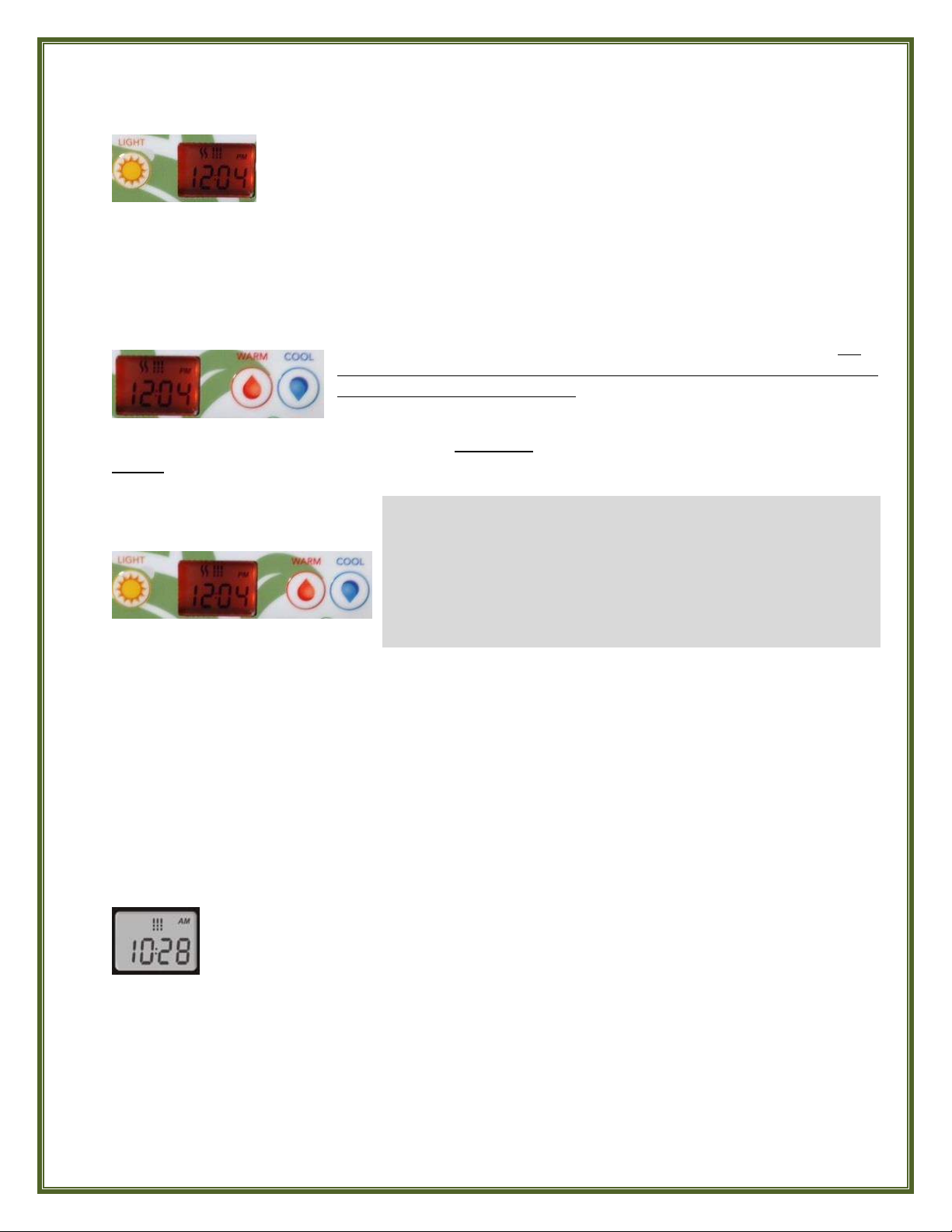
SETTING THE CLOCK
Press the LIGHT button to jump to view the next parameter, Minutes, flashing in the display,
and use the WARM or COOL button to adjust the Minutes to the correct time.
Press the LIGHT button to jump to the next parameter, the FILTER START time (FS).
Press the LIGHT button to turn On the spa’s underwater Multi-Color LED Mood
Light, if so equipped. The red indicator light adjacent to the button indicates that
the Light is On.
Use the WARM or COOL button to set your desired water temperature. For
your health and safety, the temperature Set Point limit has been preset at the
factory to not exceed 104°F (40°C). The temperature Set Point will be displayed
for 2 seconds to confirm your new selection.
PROGRAM Menu
The following parameters are set using the PROGRAM Menu:
Clock
Filter Cycle
Economy Mode
Temperature Units
Before accessing the Program Menu, be prepared with what you want your settings to be for each of
these parameters because once in the Program Menu if there is no action taken for 10 seconds, the
system will exit the Program Menu without saving any changes and you’ll have to start over.
While you are in the PROGRAM Menu, use the WARM or COOL button to adjust a parameter UP or
DOWN as needed. Press the LIGHT button to jump to the next parameter. Any changes made will be
saved after confirmation of the last parameter only.
Access the PROGRAM Menu by pressing and holding the LIGHT button for a full 5
seconds. The display will show the current clock setting with the Hour flashing.
Observe whether AM or PM is displayed above the Hour digits and use the WARM
or COOL button to adjust the Hour to the correct current time.
17
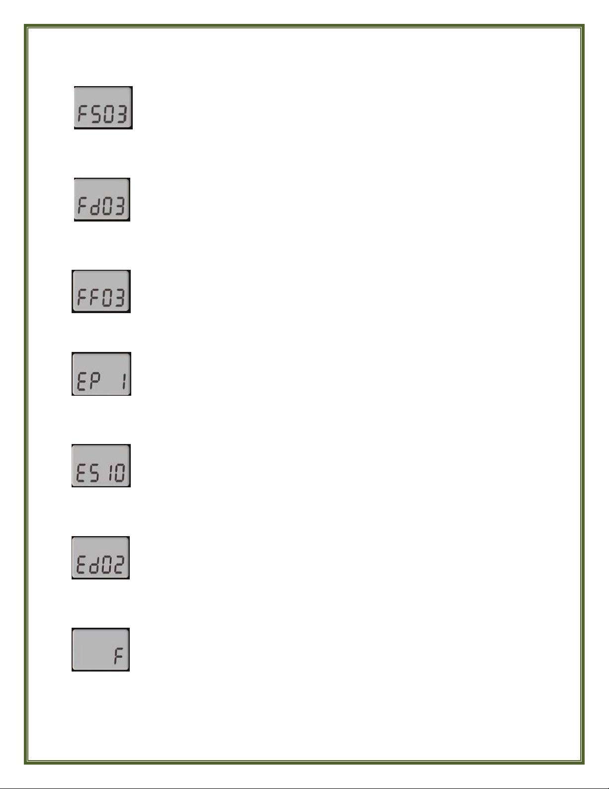
SETTING FILTER CYCLE START TIME
Press the LIGHT button to jump to the next parameter, Filter Duration (Fd).
SETTING FILTER CYCLE DURATION
Press the LIGHT button to jump to the next parameter, Filter Frequency (FF).
SETTING FILTER CYCLE FREQUENCY
Press the LIGHT button to jump to the next parameter, Economy Mode (EP).
SETTING THE ECONOMY MODE
Press the LIGHT button to jump to the next parameter, Economy Start Time (ES).
SETTING ECONOMY START TIME
Press the LIGHT button to jump to the next parameter, Economy Duration (Ed).
SETTING ECONOMY DURATION
Press the LIGHT button to jump to the next parameter, Temperature Units.
SETTING TEMPERATURE UNITS
The display will show FSXX, “XX” representing the starting hour of the Filter Cycle.
Observe whether AM or PM is displayed above the Hour digits and use the WARM
or COOL button to adjust the Hour to the desired start time.
The display will show FdXX, “XX” representing the duration in hours of the Filter Cycle.
Use the WARM or COOL button to adjust the duration. (24 = 24 Hours or Continuous
Filtration; 0 = 0 Hours or No Filtration. It is NOT recommended to set this to 0).
The display will show FFXX, “XX” representing the number of Filter Cycles desired
per 24-hour period. Use the WARM or COOL button to adjust the Frequency.
The display will show EP X, “X” representing the state of the Economy Program.
(0 = Disabled, 1 = Enabled). Use the WARM or COOL button to Enable or Disable
Economy Mode.
The display will show ES XX,“XX” representing the hour at which the Economy Mode
will become active. Observe whether AM or PM is displayed above the Hour digits and
use the WARM or COOL button to adjust the Hour to the desired Economy Start time.
The display will show EdXX, “XX” representing the Duration in hours of the Economy
Mode. Use the WARM or COOL button to adjust the duration. (24 = 24 Hours or
Continuous Economy)
Water temperature can be displayed in either Fahrenheit (°F) or Celsius (°C). The display
will show F or C. Use the WARM or COOL button to change the setting as desired.
SAVING YOUR PROGRAM SETTINGS AND EXITING THE PROGRAM MENU
After setting the Temperature Units, press the LIGHT button one final time to save all parameter
settings and exit the Program Menu. The display will return to its normal toggling of the current time
and current water temperature.
18
JET, COMPONENT AND EQUIPMENT OPERATING INSTRUCTIONS
See Pages 23 - 26 for Model E1-E2-E3-E4
Locations of Jets, Components & Equipment
JET OPERATION
Your ECO SPA is designed with a versatile jet system to allow you to select a wide variety of
massage patterns and tailor your ECO SPA to your specific massage and hydrotherapy
needs.
MASSAGE JETS
AIR CONTROLS
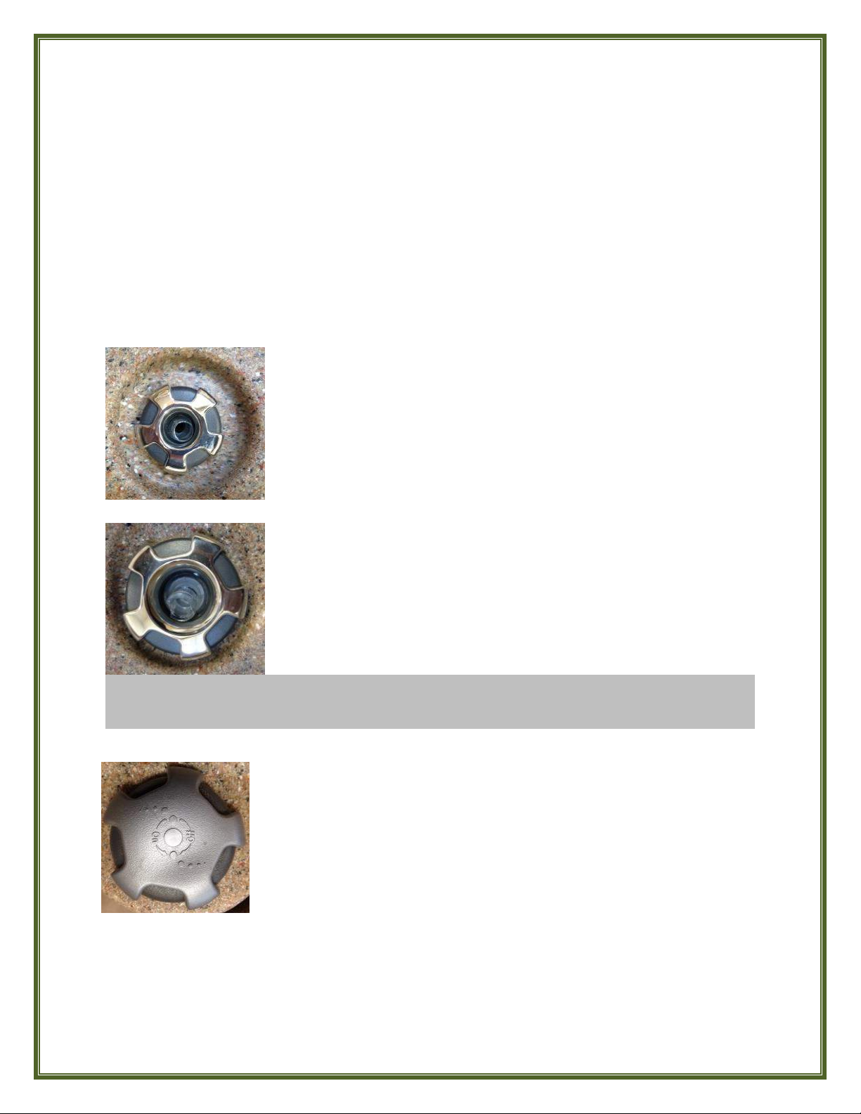
DIRECTIONAL JETS (2” or 3”) produce a tight massage stream
with that of 2” jets slightly more vigorous than that of larger 3”
jets.
To adjust the flow of Directional Jets toward a particular part of
your body, rotate the nozzle ("eyeball") of the jet to aim it in the
desired direction.
ROTO (Rotational) JETS (3” or 4-3/8”) provide a loose, swirling
massage stream with 4-3’8” jets slightly ‘softer’ than that of
smaller 3” jets.
To adjust the flow pressure of either a Directional or Roto Jet,
turn the OUTER RING counter-clockwise to increase flow to a
maximum and clockwise to decrease flow to a minimum or Off.
DO NOT FULLY DECREASE (CUT OFF) FLOW OF ALL OF THE JETS AT THE SAME TIME as this
may cause your pump to malfunction and could cause your ECO SPA to leak.
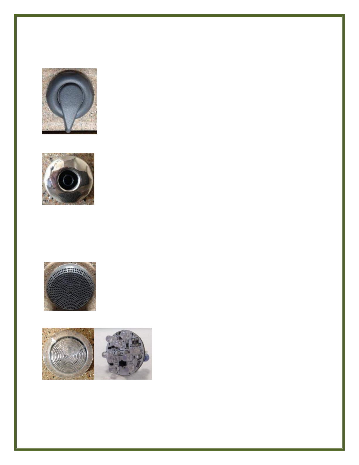
The two AIR CONTROLS are used to introduce air into the water
flow of the Massage Jets for more robust, vigorous massage.
Turn the Air Control knob counter-clockwise to the Open position to
increase jet pressure, and clockwise to the Closed position to
decrease jet pressure.
Note: When you are not using your ECO SPA and the covers are closed, ensure that the Air
Control knobs are in the CLOSED position.
This will prevent air from entering the water stream to help to maintain your water
temperature more efficiently when your ECO SPA is heating or in Filter Mode.
19
DIVERTER VALVE
OZONE JET
SUCTION FITTINGS
LED LIGHT
The 3-position DIVERTER VALVE allows water to be diverted to a zone of
jets, if desired. When the “Pointer Arrow” of the Diverter Valve is
centered in the middle (pointed towards the inside of the spa) water
flow is directed to all jets. Turning the Pointer Arrow of the Diverter
Valve knob all the way to the right or all the way to the left diverts all
water flow to a zone of jets on one side of the spa or the other resulting
in more robust massage jet action from that zone of jets.
The special 2” OZONE JET, if so equipped, located low in the footwell
area of each ECO SPA,has a fixed position nozzle; its jetstream
cannot be aimed and its flow pressure cannot be adjusted like the
massage jets.
Whenever the pump is running, this jet serves as a virtual foot
massage jet.
However, its true purpose is to introduce Ozone into the water supply during an active Filter
Cycle. Venturi action feeds Ozone from the Ozone Generator unit into this jet’s water supply and
the Ozone jet in turn releases it into the water to aid in sanitizing by killing and breaking down
certain organic materials.
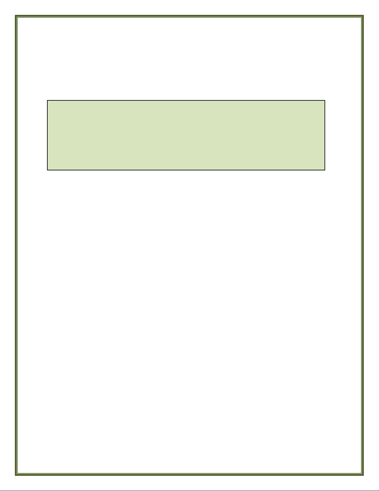
Keep the SUCTION FITTINGS (located in the foot well area) of the ECO SPA
unobstructed and free from debris at all times.
Do not remove the suction-fitting screen while the ECO SPA is connected
to electrical power.
The underwater LED LIGHT in your ECO SPA, if so
equipped, provides you with a variety of colorful mood
lighting options with its 9-LED 12 volt bulb, ranging from
solid colors to various multi-color sequence ”light shows”.
Push the LIGHT BUTTON once on the TOPSIDE CONTROL
PANEL to turn the light ON and once again to turn it OFF.
Each successive ON-OFF operation of the LIGHT BUTTON will change the lighting from one solid
color to another and eventually to cycle through the ‘light show’ variations and then Off.
A built-in timer automatically turns off the LED LIGHT after 2 hours of continuous operation.
20
TROUBLESHOOTING
WARNING: SHOCK HAZARD
Spa systems contain live electricity.
Any work within spa systems should only be performed by qualified personnel.
NO POWER TO SPA (RUNNING ON 110 VOLTS)
If the spa is connected to a 110 Volt 15 Amp grounded outlet, test and reset the Power Cable
GFCI. If this doesn’t restore power to the spa, check the outlet’s circuit breaker in the house’s
main electrical service panel.
If the spa is connected to a 110 Volt 15 Amp grounded outlet but this outlet circuit also serves
other appliances besides the spa, it may cause the breaker for this circuit in the main house
panel to trip. If this occurs, you may need to upgrade this outlet circuit to 20 Amps to handle
the spa as well as the other appliances or add a dedicated outlet circuit for the spa. In either
case, please consult your licensed electrician.
GFCI IS TRIPPING (RUNNING ON 220 VOLTS)
For a new 220 Volt installation or for an ECO SPA recently converted from 110 Volt to 220
Volt operation the problem is most likely with the wiring of the 220 Volt circuit’s GFCI breaker.
If GFCI trips instantly the problem is usually the neutral wire path in the GFCI. For an ECO
SPA that has been installed and running satisfactorily for some time, the problem can be
isolated by unplugging or disconnecting the Ozonator unit, Heater, Pump and Light from the
Control System (“Pack”) one at a time and resetting the GFCI each time to see if the spa stops
tripping.
PUMP SURGES CONSTANTLY
This is caused by low water level. Check that the water level is 2” above the highest jet. Be sure
you are using the correct closed-top Filter Cartridges.
JET LOW FLOW PROBLEMS
Check to be sure that the Jets are turned to the Open position (Counterclockwise) and that the
Air Controls are in the Open position (Counterclockwise). Jets can be removed if necessary to
check for blockage or for replacement by turning the Jet counterclockwise until you hear a
“click”. Then pull the Jet straight out of the Jet Body. Reinstall the Jet by pushing it into the Jet
Body, making sure it’s in the correct position with the square tab on the underside of the Jet
face aligned to the slot in the Jet Body, and turn it clockwise.
The GFCI power cord must be tested to insure proper operation. To test, simply
depress the button marked TEST on the GFCI unit. The unit should stop operating and
the button marked RESET should pop up. Push the RESET button and the unit’s pilot
light will come on indicating that the unit is operating normally. IF THE INTERRUPTER
DOES NOT PERFORM IN THIS MANNER, A GROUND CURRENT IS FOLLOWING
INDICATING THE POSSIBILITY OF ELECTRIC SHOCK. DISCONNECT THE POWER UNTIL
THE FAULT HAS BEEN IDENTIFIED AND CORRECTED.
This manual suits for next models
3
Table of contents
Popular Hot Tub manuals by other brands


 owner's manual")


CalderaSpas
CalderaSpas CalderaSpas Utopia Series owner's manual

anko
anko SS-601A user manual

CalderaSpas
CalderaSpas CANTABRIA owner's manual

Dimension One Spas
Dimension One Spas HYDRO SPORT Installation and owner's guide

Bestway
Bestway Lay-Z-Spa Maldives HydroJet Pro manual

Dimension One Spas
Dimension One Spas Nautilus Specifications