Eco Spar AURIGA 23 kW Specification sheet

MANUAL for INSTALLATION and OPERATION of
AURIGA 23 kW

Table of contents
1.0. PRECAUTIONS AND SAFETY ...................................................................................................3
2.0. TECHNICAL CHARACTERISTICS ................................................................................................4
2.1 Accessories ..........................................................................................................................4
2.2 Assembling the control panel ..................................................................................................5
2.3 Technical description .............................................................................................................5
2.4 Technical data and dimensions ................................................................................................6
3.0 INSTALLATION ......................................................................................................................7
3.1 GENERAL RULES ....................................................................................................................7
3.2 CONNECTION OF THE OUTER AIR PIPE .......................................................................................8
3.3 EXHAUST GAS SYSTEM ...........................................................................................................9
3.4 EXHAUST GASES AND INSTALLATION ........................................................................................9
3.5 USABLE PIPES .......................................................................................................................9
3.6 INSTALLATION SCHEMES (optional) ..........................................................................................9
3.7 REAR END OF THE EXHAUST GAS PIPE .......................................................................................10
3.8 CONNECTION TO THE ELECTRICAL POWER SUPPLY ......................................................................10
4.0 USAGE ................................................................................................................................11
4.1 SAFETY PRECAUTIONS ............................................................................................................11
4.2 FUELS ..................................................................................................................................11
4.3 TECHNICAL SPECIFICATIONS ....................................................................................................11
4.4 INSTALLATION ......................................................................................................................12
5.0 PELLETS ...............................................................................................................................17
5.1 STORAGE OF PELLETS .............................................................................................................17
5.2 POURING THE PELLETS ...........................................................................................................17
6.0 CLEANING AND MAINTENANCE ...............................................................................................18
6.2 CLEANING AND MAINTENANCE OF THE PELLET STOVE .................................................................18
7.0 ELEKTRICAL CENTRAL-LINE .....................................................................................................21
8.0 FAILURES / CAUSES / SOLUTIONS / ATTENTION .........................................................................21
9.0 POST-SALE SUPPORT .............................................................................................................22
10.0 WARRANTY ........................................................................................................................22

Dear buyer, we thank you for choosing this product.
This product is made with attention to all materials used and technologies employed. It was designed to satisfy your
needs for a functional and safe product.
By using this instruction manual you will learn how to use your pellet-burning stove properly; please read it carefully
before use.
This product is manufactured in accordance to the following standards:
-89/106 CEE (CPD) production materials
-73/23 CEE (LVD) electrical safety
-2004/108 CEE (EMC) electromagnet compatibility
and norms:
-EN303-5
1.0. PRECAUTIONS AND SAFETY
The Pellet stoves are designed to provide maximum safety and ease of operation. However it is necessary to observe
the following safety guidelines to ensure an accident-free operation.
1. It is recommended that the authorized maintenance staff should make sure not to leave bare parts of the wires not
completely inserted into the connectors, so that no live parts of the wires may contact other objects.
2. The installation should be performed by specially trained staff authorized by the manufacturer; after its
completion, the staff is obliged to give to the end user a statement which states that the pellet stove is connected
according to all applicable standards and that the staff takes over the complete responsibility for its installation.
3. It is important to observe all applicable national laws of the country where the product is to be installed.
4. The manufacturer does not bear any responsibility if the above stated obligations are not observed.
5. The Instruction manual is an inseparable part of the product. In case the Instruction manual is missing or lost, the
end user should have it provided by the seller.
6. This pellet stove should be used only for the purpose it is intended for.
7. The manufacturer does not bear any responsibility for damages suffered by people, animals or objects caused due
to installation errors or improper use.
8. After removing the packaging, the user should check whether all the parts are in place and if any part is missing,
the user should have the seller provide the missing parts.
9. Only original parts must be used for replacement of faulty ones. Please refer only to authorized service agents
holding certificate for maintenance of equipment.
10. For proper operation of the product, it should be serviced once after consumption of 1800 kg certified pellets or
once a year. The service should be performed by authorized staff. Otherwise, the warranty will become void.
For safety purposes, the following must be strictly observed:
The pellet stove is not to be operated by children or disabled persons.
It is forbidden to install the product in a toilet, damp spaces, such as laundry room, as well as to touch
the pellet stove with wet hands or legs. A power supply socket with a ground terminal (safety socket)
should provided to power the appliance.
It is forbidden to change or cancel the safety precautions without an authorization by a authorized
technician.
Do not pull, tear, burn the cables coming out from the product even if it is off.
Do not leave the packaging close to children or disabled persons.
During the normal operation of the product, the door should be closed at all times.

Avoid direct contact with hot parts of the product.
Check if there are difficulties while turning the product on after a long period of non- operation (see
chapter 6.0).
The pellet stove is designed to work even in extreme weather conditions, however, in case of strong
wind or frosty conditions, the safety systems might trigger on and shut the pellet stove off. In such case,
the user should contact the authorized service. It is not advisable to disable or reset the safety devices
on the user’s discretion.
Fire extinguisher should be in reach in case of accidental occurrence of fire in the exhaust gas pipe.
2.0. TECHNICAL CHARACTERISTICS
2.1 Accessories
Before the initial installation of the pellet stove, you should check whether all accessories are in place:
Pipe scraping lever
Remote controller
Control panel + screws for its mounting (in the reservoir for pellets)
Documentation (warranty, instruction manual, service centers)
Important: Read carefully the whole documentation and keep it attentively.
2.2 Assembling the control panel
When you take the pellet stove out from its packaging, in the reservoir for pellets you will find the control panel (2)
wrapped in a foil and M5 screws (3) in a bag, which are used for its assembling (1). Take out the control panel (2), put
the cable (4) through the hole in the panel (see figure) and connect it to the card. Take the M5 screws from the bag
and attach the panel to the cover.
Important: When connecting the panel, be careful not to cut the cable

2.3 Technical description
The AURIGA 23 kW is designed for heating residence or office spaces, as well as an additional heating, at the same
time contributing to the more pleasant ambience. Suitable for central space heating. Mantle heat exchanger.
The hearth of the pellet stove is made of very thick cold-rolled metal sheet, as well as a supporting structure which is
coated with high temperature and high quality powder -like color. The upper part, the lower part and the burner are
made of a special metal sheet.
The inner part of the burner is coated with double metal sheet which guarantees higher thermal power of the pellet
stove.
The burner has a door with ceramic glass which is heat resistant at a temperature of up to 700oC. By this solution we
wanted you to see the fire inside the burner, at the same time avoiding contact with the dangerous sparkles and
appearance of smoke. The door is hermetically closed.
Table
ARESERVOIR COVER NASH DRAWER
VCONTROL PANEL I DOUBLE METAL SHEET OF THE BURNER
S PELLET RESERVOIR L BURNER
D PIPE CLEANING LEVER P ELECTRIC POWER SUPPLY SOCKET
F CERAMIC GLASS R SIDE COLORED METAL SHEET

2.4 Technical data and dimensions
Model of the pellet stove:
Kw 23
Height
mm
1250
Width
mm
585
Depth
mm
555
Weight
kg
160
Diameter of air intake pipe
mm
38
Diameter of exhaust gas pipe
mm
80
Maximum heating (*) volume
m2
220
Nominal thermal power (Ptn)
kW
23
Decreased thermal power (Ptr)
Nominal thermal power (water)
kW
kW
3
20
Max. consumption per hour
kg/h
5
Min. consumption per hour
kg/h
1.5
Reservoir capacity
Boiler capacity
Kg
Liters
30
35
Utilization at nominal thermal power
% 92
Nominal electrical power
W
340
Nominal voltage
V
230
Nominal frequency
Hz
50
The above table is made on the basis of tests conducted using wooden pellets with caloric power of 18220 Kj/kg
(equal to 4350 Kcal/kg)
(*) Value depending on the place of installation.
The above values are indicative, not obligatory. The manufacturer retains his right to change the values in every
moment in order to improve the performance of the product.

3.0 INSTALLATION
3.1 General rules
Knowing that the proper assembly is very important, as well as the proper connection of the exhaust gas system
and that the possible errors made during the assembly are not covered by the warranty of MANUFACTURER , our
company advices the installation to be made after the following checks:
- Minimum volume of the space where the pellet stove is installed (avoid spaces smaller than 40m3);
- Provide good air flow;
- Observe all the norms;
- Proper operation of the exhaust gas system;
You should also observe the following legal normatives:
- Bans on installation
- The right to occupy a space
It is not allowed an installation of the pellet stove in bedrooms, toilets, and in spaces where already exists another
heating body without sufficient air intake (pellet stove, fireplace etc.). It is not allowed the installation of the pellet
stove in spaces containing explosive materials.
The installation of the pellet stove should be made in accordance to all practical knowledge. The space around the
pellet stove should be made of stone, cement or other fireproof material. The pellet stove generates heat around the
burner. Therefore, you should avoid contact of inflammable materials with the burner (alcohol, paper, plastics …)
Minimal distance from the inflammable materials is 200 mm.
- If the floor is made of inflammable material (parquet ...) it should be adequately isolated.
- The metal pipes intended for the gas exhaust should be at a distance of 1,5 m from inflammable materials.
- We recommend that the pellet stove should be installed as closer as possible to the exhaust gas system, always
having maximum 3+1T curves and maximum 3 m of horizontal flow with minimal elevation of 3-5%.
As soon as the place of installation is defined, remove the cardboard and the other protective material and check
whether the door is properly closed.
3.2 CONNECTION OF THE OUTER AIR PIPE

For proper operation and proper distribution of the temperature, the pellet stove should have sufficient air intake
and to be placed on suitable place (a special hole for air intake can be made).
The hole for air intake should be 100 cm2minimum and there should not be any obstacles.
The air may be also taken from another room which is constantly ventilated and in which there is no other pellet
stove or other system which needs an air intake. That room can not be a bedroom, toilet, another space where there
is a danger of fire, such as a garage, basement, warehouse containing inflammable materials.
If there is a pellet stove in the same room using gas from an open system or any other source of harmful gas, the air
intake should be directly from outside.
AN EXAMPLE OF CONNECTION DIRECTLY FROM OUTSIDE
For the sake of proper operation of the pellet stove a direct connection from outside is possible, using metal pipe of
80 mm provided with silicon sealer. It is important that the front opening of the pipe is protected against wind, water
or other, using a curve of 90o turned downwards.
Manufacturer does not bear any responsibility if the above indicated instructions are not observed.
For proper placement of the air intake you should observe the following distances: 1,5 m underneath, 1,5 m
horizontally, 0,3 m from above the doors, windows 2,0 m from the exhaust gas system.
3.3 EXHAUST GAS SYSTEM
It is always important to know that the exhaust system is as important as the pellet stove.
The installation of the exhaust system should be performed by authorized persons. The authorized person should be
guided by the following data:
23 kW
Draft of the pellet stove Pa 12
Mass of the combusted air g/s 5.3
CO measured for 13% oxygen % 0.0196 0.015
Temperature of the exhaust gases C 160.7 173.8
3.4 EXHAUST GASES AND INSTALLATION
The exhaust gas system operates as a result of depression which occurs in the combustion area. It is very important
for the exhaust gas system, above marked as SIG, to be made of certified materials and:
- to be hermetically closed, meaning the system should be made of special pipes with adequate silicon sealer.
- to be able to operate under high pressure and under temperature ranging from 200-250oC (pipes with thickness not
less than 1 mm is recommended).
If the pellet stove is connected to the existing system, the system should be checked by an authorized person. The
system can not be installed indoors. Periodical cleaning of the exhaust gas system is recommended.
3.5 USABLE PIPES
The pipes used for the exhaust gases should be resistant, smooth from inside, made of metal and to have silicon
sealer. The diameter of the pipes up to 3 m long should be 80 mm or 100 mm for pipes longer than 3 m or over 1200
m height above sea level.
The length is calculated along the whole horizontal and vertical length, counting each curve of 90oas 1 m of length.
ATTENTION
Do not connect the system to the existing system or to the aspiration system.
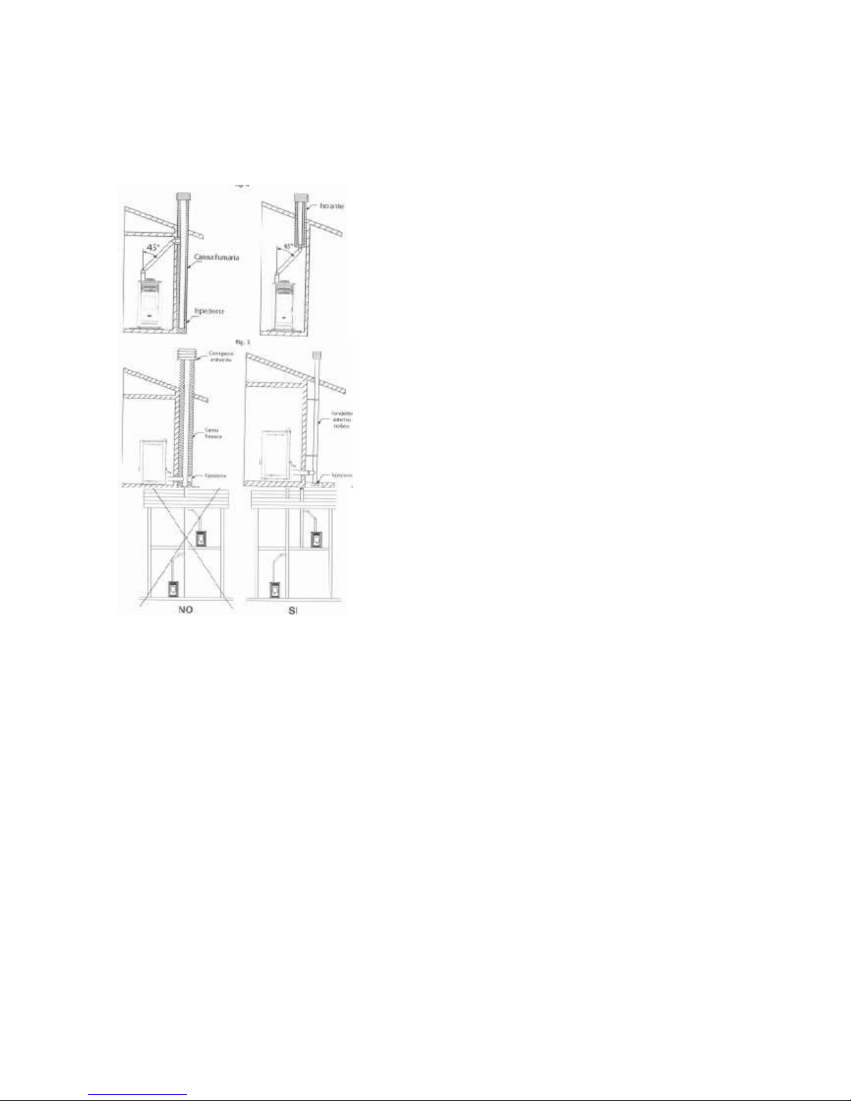
3.6 INSTALLATION SCHEMES (optional)
3.7 REAR END OF THE EXHAUST GAS PIPE
The rear end of the exhaust gas pipe is intended for proper exhaust of the gases in the atmosphere, its protection
against rain, snow or any other objects in order to guarantee excellent exhaust of the gases in windy conditions, as
well.
The rear end of the exhaust gas pipe should meet the following requirements:
- the inner part should be the same as that of the pellet stove;
- the outer part should not be less than twice than the one of the pellet stove;
- the manufacture should protect the system against rain, snow and wind;
- easy dissassembling for cleaning purposes;
- possibility for atractive finish which fits to the building.
The system should not have obstacles at a distance of less than 10 m, such as walls, trees. In such a case the system
should end 1 m above the obstacles, and in case of other systems, 2 m from them, and in every case the system
should be at least 1 m above the roof.

OPERATIONAL PROBLEMS DUE TO DEFECTS OF THE SYSTEM CAPACITY
Besides all influencing atmosphere agents, the wind is the most important agent for the system operation.
3.8 CONNECTION TO THE ELECTRICAL POWER SUPPLY
The product should be connected to the electrical power supply. Our pellet stoves are supplied with a medium
temperature persistent cable. In case you need to replace the cable, call an authorized service agent. Before you
connect to the electrical power supply, you should check the following:
- whether the characteristics of the electrical power supply meet the requirements indicated on the plate
- whether the connection is properly grounded
- the cable should not have temperature higher than 75oC.
In case of a direct connection to the electrical power supply, call an authorized person, an electrician. If you do not
use the pellet stove for a longer time period, you should disconnect it from the electrical power supply. The
connection should be easily accessible.
4.0 USAGE
4. 1 SAFETY PRECAUTIONS
Taking into consideration that the pellet stove develops high temperature, the young and adult persons should be
careful, and especially the children. It is forbidden to pour water or any other liquid which might cause temperature
shock. Do not place inflammable objects near the pellet stove.
4.2 FUELS
The only fuel which is allowed for use by the Manufacturer pellet stove is the wooden pellets.
In order to guarantee combustion without problem, the pellets should be kept in a dry place. We recommend usage
of high quality pellets, compact and not powder-like. Inform yourself at your pellet vendor, which pellets are the
best. Keep the pellets on a distance from the pellet stove, not less than 1,5 m (see chapter 5.0).
ATTENTION
The boiler is manufactured and tested only by using certified ECOSPAR pellets. The manufacturer does not take any
responsibility if you use non-certified pellets also on quality and quantity of used pellet per season caused of pellet
quality.
4.3 TECHNICAL SPECIFICATIONS

All specifications are listed below.
Electrical power supply 230V, 50/60Hz, maximum consumption 13/20 mA.
Inputs:
Exhaust gas temperature –Type J
Outer thermostat - contact
Probe NTC temperature room –NTC 10 k
Outputs:
Exhaust gas aspirator –230 V
Exchanger - 230 V
Low-range gear lever –230 V
Heater - 230 V
Room specifications:
Operative temperature –from 0 to 60oC
Storage temperature –from -10 to 60oC
Maximum relative humidity –95%
Mechanical specifications:
Dimensions 125 x 101 x 35 mm
Weight 250 gr
Connectors:
4.4 INSTALLATION
All required cables and connectors are put into the pellet stove. The installation is quick and simple.
Before each assembling of the system, an automatic test of the system is performed for its proper operation.
When you turn on the product for the first time, you should do the following:
When you are sure that the assembly is properly done, it is possible to start initial turning on the pellet stove, which
will allow its proper setting. The setting might be made either through the control panel or the software.
For normal operation of the stove, it should be changed some parameters depend on the installation of the stove,
different type pellet, length of the chimney etc… For that purpose, we explain which parameter what it means so you
can easy understand how the stove works. To enter in parameters follow these steps:
Push the "arrow" button so you go to "settings" menu (gear icon) last right on the display. Should be on position
"OFF", then with the "+" go to menu 9 for the AIR models or 8 for the WATER models and here you can get the code
pressing "set" (enter) to continue to the service parameters of the menu. The code is the sum of the 4 digits of the
number that appears on menu 8 (or 9) plus 1. You will enter it with the button "+" (when you push on display counts
1,2,3,4….up to the number of the code), then push again "set" (enter) and you are in the service settings menu. You
have to press "+" until you go to menu "par" press again "set" (enter). Now you are in the service menu of the stove
choose the menu settings number push "set" (enter) and you can change the parameters of the stove. Check the
table..

RECOMMENDED SETTINGS FOR AURIGA 23KW
0. Fuel ignition timeout --> [20]
36. Power 3 fan 2 speed --> [0]
73. User fuel feeder 1 ON time factor -->
[100]
1. Ignition test timeout --> [10]
37. Power 4 fan 2 speed --> [0]
74. User fuel fan 1 speed factor --> [100]
2. Fuel type --> [0]
38. Power 5 fan 2 speed --> [0]
75. Wood fuel fan 1 speed factor --> [100]
3. Heat up feeder OFF time --> [210]
39. Quickheat fan 2 speed --> [0]
76. Selected configuration --> [1]
4. Heat up feeder ON time --> [110]
40. Stop fire fan 3 speed --> [240]
77. 2nd room temperature --> [0.0]
5. Fuel ignition feeder 1 OFF time -->
[200]
41. Test fire fan 3 speed --> [240]
78. Flame ON level --> [0]
6. Fuel ignition feeder 1 ON time --> [20]
42. Heat up fan 3 speed --> [240]
79. Flame OFF level --> [0]
7. Ignition test feeder 1 OFF time -->
[100]
43. Fuel ignition fan 3 speed --> [240]
80. Flame OFF detection delay --> [0]
8. Ignition test feeder 1 ON time --> [10]
44. Ignition test fan 3 speed --> [240]
81. Underpressure setpoint --> [0]
9. Power 1 feeder 1 OFF time --> [1]
45. Power 1 fan 3 speed --> [240]
82. Min. (error) underpressure/airflow -->
[0]
10. Power 1 feeder 1 ON time --> [13]
46. Power 2 fan 3 speed --> [240]
83. Underpressure/airflow error delay -->
[0]
11. Power 2 feeder 1 OFF time --> [1]
47. Power 3 fan 3 speed --> [240]
84. Accumulator temperature --> [0]
12. Power 2 feeder 1 ON time --> [1]
48. Power 4 fan 3 speed --> [240]
85. T1-T2 for water pump OFF --> [0]
13. Power 3 feeder 1 OFF time --> [1]
49. Power 5 fan 3 speed --> [240]
86. Boiler to accu. temperature drop -->
[0]
14. Power 3 feeder 1 ON time --> [1]
50. Cool fluid exit temp. diff. --> [10]
87. Keep fire fan 1 speed --> [0]
15. Power 4 feeder 1 OFF time --> [1]
51. Water/air temperature --> [38.0]
88. Keep fire feeder 1 ON time --> [0]
16. Power 4 feeder 1 ON time --> [1]
52. Water temperature in stove mode -->
[80]
89. Keep fire fan 1 duration --> [0]
17. Power 5 feeder 1 OFF time --> [1]
53. Cool fluid entry temp. diff. --> [10]
90. Keep fire period --> [0]
18. Power 5 feeder 1 ON time --> [33]
54. Ignition test gases temperature -->
[80]
91. Feeder 2 delay/ON time factor --> [0]
19. Stop fire fan 1 speed --> [240]
55. Modulation start gases temperature -
-> [320]
92. Pellets quality --> [1]
20. Test fire fan 1 speed --> [140]
56. Heating device OFF gases
temperature --> [75]
93. Wood quality --> [1]
21. Heat up fan 1 speed --> [150]
57. Maximum (error) gases temperature -
-> [340]
94. Time to service --> [0]
22. Fuel ignition fan 1 speed --> [160]
58. Fan 2 as ambient min. gases temp. -->
[100]
95. Stove cool fluid entry temp. diff. -->
[5]
23. Ignition test fan 1 speed --> [170]
59. No fuel (error) gases temperature -->
[60]
96. Stove cool fluid exit temp. diff. --> [2]
24. Power 1 fan 1 speed --> [150]
60. Fan 1 blow cleaning period --> [60]
97. T1-T2 for min. modul. speed --> [0]
25. Power 2 fan 1 speed --> [0]
61. Fan 1 blow cleaning duration --> [45]
98. Full level --> [0]
26. Power 3 fan 1 speed --> [0]
62. Fan 1 blow cleaning speed --> [240]
99. Low level --> [0]
27. Power 4 fan 1 speed --> [0]
63. Air pulse cleaning duration --> [0]
100. Empty level --> [0]
28. Power 5 fan 1 speed --> [200]
64. Chamber cleaning duration/rot. -->
[0]
101. Blow out duration --> [180]
29. Test fire fan 2 speed --> [0]
65. Ash extraction auger duration --> [0]
102. Antifreeze temperature --> [0]
30. Stop fire fan 2 speed --> [0]
66. Ash extraction auger period --> [0]
103. Water pump minimum speed --> [0]
31. Heat up fan 2 speed --> [0]
67. ON temperature --> [40]
104. Water pump maximum speed --> [0]
32. Fuel ignition fan 2 speed --> [0]
68. OFF temp./T1-T2 for
max.modul.speed --> [35]
105. Reserved 105 --> [0]
33. Ignition test fan 2 speed --> [0]
69. Anti-condensation exit temp. --> [0]
73. User fuel feeder 1 ON time factor -->
[100]
34. Power 1 fan 2 speed --> [0]
70. Heat up duration --> [160]
74. User fuel fan 1 speed factor --> [100]
35. Power 2 fan 2 speed --> [0]
71. Fuel ignition temp. check samples -->
[6]
75. Wood fuel fan 1 speed factor --> [100]
0. Fuel ignition timeout --> [20]
72. Fuel ignition temperature rise --> [2]
76. Selected configuration --> [1]

Using Fumis ALPHA keyboard
Fumis ALPHA keyboard with remote control
Figure 1: Fumis ALPHA keyboard and remote control
The Fumis ALPHA capacitive touch keyboard is designed intuitively. It enables users at home to operate with the Fumis
ALPHA controller.
Note
For best performance keep the keyboard clean. Stains (for example, grease) on the buttons can send
the signal that the button was pressed.
The Fumis ALPHA infrared remote control is intended for day-to-day use when the combustion system is fully
configured and operational. It is used for modifying the burning power and temperature settings, and enables you to
turn the combustion system on or off. The remote control unit is optional.
At the top of the Fumis ALPHA keyboard are located indicators for various alarms, timer mode operation, and menus.
The IR sensor is used for remote control unit.
The display shows the set or current values for the currently selected menu option. With buttons you can navigate
through the menu and control the operation of the Fumis ALPHA controller. Refer to the Table 1: Fumis ALPHA
keyboard buttons on page 14 for descriptions of the buttons.
The Fumis ALPHA keyboard is also equipped with the beeper, which provides the keyboard feedback signals. The
following sound signals are available:
Short high tone: sounds when navigating the menu and editing the settings
Long low tone: sounds in case of an invalid operation (wrong button pressed)
Long high tone: in case of and alert, this tone sounds with the user defined loudness, and in
case of an error, this tone sounds with 100% loudness. For description of alerts and errors,
refer to chapter Troubleshooting on page 24.
Button
Description
Power ON/OFF button is used for turning the combustion
system on or off and for deleting errors/alerts. Press and
hold the button for 1 second.
Menu buttons (left and right buttons) are used for
navigating the first level menu context. The currently

selected menu context is indicated with the corresponding
icon at the top. In addition, these buttons are used in the
edit mode.
Edit buttons (plus and minus buttons) are used for
navigating the submenus and increasing/decreasing values
in the edit mode, when the selected value blinks.
Enter button is used for entering the edit mode and
confirming the set values, or selecting the additional
submenus.
Escape/Cancel button is used for discarding the changes
and returning up one level in the menu. If you press and
hold this button for more than 3 seconds, the last error or
alert code is displayed.
Table 1: Fumis ALPHA keyboard buttons
Menu structure
Figure 2: Menu structure

Note
The Fumis ALPHA menu structure depends on the configuration and options. The menu structure in
Figure 35 shows all possible menu entries. Depending on the selected configuration, some entries are
not available. In such cases the menu entry is not included and submenus are renumbered accordingly.
The display values are for representational purposes only and may differ from the actual display values.
Navigating the menu
To navigate the first level menu context use the left and right arrow buttons. The display shows the setting for the first
submenu entry.
To navigate the second level menu (the submenu), use the plus and minus buttons to move up and down. The menu
structure in the figure is inverted, so it may seem you are moving down the menu, but you are actually going up. For
easier navigation through the second level menu, the corresponding entry number in brackets is displayed briefly.
To modify a setting in the menu, press the Enter button to enter the edit mode for the selected setting. The display
value starts blinking. Use the plus and minus buttons to change the value. To move through the steps in the edit
mode, use the left and right arrow buttons. When finished, press the Enter button to save the setting and exit the edit
mode. The display returns to the menu entry you edited.
The display shows the set value, or the actual value, depending on the setting. For example, when you edit the
temperature, you enter the desired room temperature. After you exit the edit mode, the display shows the actual
temperature (which may differ from the set temperature). When you edit the fuel quality setting, the display shows
the set value.
To enter the third level menu, press the Enter button and then use the plus and minus buttons to move between the
entries. The procedure for modifying the settings is the same as in the second level menu.
To exit the edit mode without saving the changes, press the Cancel button. This button is also used for returning up
one level in the menu. For example, if you are editing the Program 3 in the Weekly Timer Periods menu entry, press
the Cancel button to discard the changes and return to Program 3. Pressing the Cancel button moves to Weekly Timer
Periods, then to Clock, and then to Burning Power in the Power menu context.
Setting the clock
The Fumis ALPHA keyboard enables you to set the current time and date.
To view the current time, press the menu button to enter the Time context. The current time is shown on display.
To set the time and date, in the Time context press the Enter button. The hour value is blinking. With the edit buttons
set the desired hour. Then press the right menu button. The minute value is blinking. Set the desired minute. Press the
right menu button and set the date in the same manner. The date is set in the format dd.mm.yyyy. Then press the
right menu button and set the day of the week. Set the corresponding number between 1 (Monday) and 7 (Sunday).
Confirm the time and date settings by pressing Enter.
Setting the room temperature
With the Fumis ALPHA controller you have two options for setting the room temperature. You can:
Use weekly timer programs
Set or modify the room temperature manually
Using the weekly timer programs you can fully automate the operation of your combustion system and little or no
user intervention is required. For more information refer to chapter Setting the weekly timer programs on page 16.
You can also set or modify the room temperature manually. If you are using the weekly timer programs, this enables
you to temporarily override the program settings. The program settings are reset when conditions, set with the timer,
are met (for example, end time is reached and the combustion system turns off).

To view the current room temperature, press the menu button to enter the Temperature context menu. The current
room temperature value is shown on the display.
To set the desired room temperature, in the Temperature context menu press the Enter button. The display shows the
set target temperature in the edit mode (the value is blinking). You can increase or decrease this value with the Edit
buttons. When finished, press the Enter button to confirm the set temperature. The display shows the current room
temperature.
Note
You can also use the remote control to set the desired room temperature.
In case your combustion system is equipped with the second room fan, you can also set the desired temperature for
the second room.
Note
The decimal points for setting the temperature depend on the configuration.
Setting the output power
The Fumis ALPHA controller regulates your combustion system for optimum performance. You can override these
settings and modify the burning power to reach the desired room temperature faster, or conserve fuel. The burning
power setting influences the fuel feeder and fan speed settings.
The burning power setting represents the maximum burning power the combustion system will use to heat up the
environment. When the set temperature is reached, the burning power is decreased automatically. For example: if you
choose burning power 3, the combustion system will only modulate between power 1 and 3 (based on desired
temperature).
To view the current burning power, press the menu button to enter the Power context. The current burning power
level value is shown on display.
For faster heating up to the desired room temperature you can increase the burning power setting. In the Power
context press the Enter button. The display shows the burning power in the edit mode (the value is blinking). You can
increase or decrease this value with the Edit buttons. When finished, press the Enter button to confirm the set burning
power. Display shows the current burning power level. The fuel feeder is dosing the fuel faster and the heat exchange
fan operates faster to increase the output power.
To conserve with fuel and energy, you can decrease the burning power setting. The fuel feeder and fan will operate
slower and the set room temperature is reached slower.
Note
You can also use the remote control to set the desired burning power.
Setting the weekly timer programs
The Fumis ALPHA controller enables you to set the weekly timer programs to automate the operation of the
combustion system. You can set six different programs and select three programs for each day of the week. The
program defines the start time, the end time, and the desired temperature.
To set a program, press the menu button to enter the Time context and then press the edit button to select the
Weekly timer periods. The display shows (3). Press Enter to select Program 1, display shows (P1), and then press Enter
again to access the edit mode for Program 1. The start time hour value is blinking. With the edit buttons set the
desired start time hour. Then press the right menu button. The start time minute value is blinking. Set the desired start
time minute. Press the right menu button and set the desired end time. Then press the right menu button to set the

desired room temperature for the selected time period. Confirm the program settings by pressing Enter. Repeat the
procedure to set the programs.
Example:
Program 1
Program 2
Program 3
Program 4
Program 5
Program 6
ON
OFF
ON
OFF
ON
OFF
ON
OFF
ON
OFF
ON
OFF
5:30
7:30
8:00
11:30
12:00
23:00
17:00
23:00
20:00
22:30
4:00
7:00
16⁰C
18⁰C
19⁰C
18⁰C
17⁰C
15⁰C
To set the programs for each day of the week, press the menu button to enter the Time context and then press the
edit button to select the Weekly timer days. The display shows (4). Press Enter to select Monday, display shows (d1),
and then press Enter again to access the edit mode for Monday. The 1. program value is blinking. With the edit
buttons set the desired program. Then press the right menu button. The 2. program value is blinking. Set the desired
program. Confirm the program settings by pressing Enter. Repeat the procedure to set the programs for all weekdays.
Example:
To enable or disable the operation of the combustion system with the weekly timer programs, press the menu button
to enter the Time context and then press the edit button to select the Weekly timer ON/OFF. Press Enter and toggle
the weekly timer on or off. If you disable the weekly timer operation, set the combustion system operation manually.
Example:
You can disable the weekly timer programs in the time of vacations.
Program overlapping:
If the programs overlap, the program with higher number assumes priority (for example: P2 assumes priority over P1;
P4 over P3, P2 and P1; P6 over P5, P4, P3, P2 and P1).
The following figure shows the working of combustions system in case of P1, P2 and P3 programs overlapping.

time
Program/Temperature
setpoint
P1 (20°C)
P2 (21°C)
P3 (22°C)
Heating device ON
Heating device OFF time
LEGENDA:
P1 à7:00h (ON); 20:00h (OFF); temperature setpoint 20°C
P2 à9:00h (ON); 11:00h (OFF); temperature setpoint 21°C
P3 à13:00h (ON); 17:00h (OFF); temperature setpoint 22°C
5 7 8 9 10 11 12 13 14 15 16 17 18 19 20
temperature setpoint in timer mode
Heating device; ON
Heating device OFF
Figure 3:
Programs overlapping
Setting the fuel options
The Fuel menu context shows the fuel autonomy and enables you to select the fuel quality. In the combined
wood/pellet combustion systems, you can select the wood or pellet fuel type.
The Fuel autonomy value shows how much fuel is left in the container (in days or hours). For example, value 3d means
there is enough fuel for three more days of operation. If you are using the pellet level sensor, the fuel autonomy is
monitored automatically. You can also manually set the fuel autonomy. When you fill the empty container (up to full
level in the magazine), set the fuel autonomy to FULL. The display shows how long the fuel in the container will last (in
days or hours). When there is fuel for less than an hour left, the display shows LO (low). When the container empties,
the Fuel autonomy sets to OFF and icon (no fuel) lights up on user interface. Fill the container and set the Fuel
autonomy setting to FULL. If you refill the fuel container before it is completely empty, remember to reset the fuel
autonomy to FULL. Be careful to fill up the fuel to the “full” level in the magazine, otherwise the fuel autonomy will
not display properly.
Note
For the above-mentioned to work properly the combustion device has to support Fuel autonomy
function.
With the combined wood/pellet combustion systems the burning can be performed manually, using the wood fuel, or
automatically, using the pellet fuel. If wood mode is selected, the system burns on wood until the gases temperature
in the burning chamber falls below the set threshold (the wood burns out). Then the combustion system switches to
pellets automatically and operates in pellet mode (option). To switch back to wood mode, set the Fuel type option
value to 2to select the wood fuel type.
You can optimize the burning and feeder options based on the type and efficiency of the fuel used. With the Fuel
quality options you can select the level of pellet and wood combustion efficiency, where low value stands for more
humid fuel with less combustion efficiency, and high value stands for fuel with high combustion efficiency. You can
select between values 1 to 3.

Modifying the setup options
In the Setup menu context you can set the options for Key lock, Idle display brightness, Idle display mode, Beeper
volume, Manual feed and view the Time to service (option, read only).
To modify the setup options, press the menu button to enter the Setup context. To move between the setup options,
press the edit buttons to display the settings. To modify a setting, press Enter and use the edit buttons to
increase/decrease the value. When finished, press the Enter button to confirm the set value.
The Key lock option enables you to lock the keyboard in order to prevent accidental changes of the settings. With the
key lock enabled, you can navigate the menu to display current values, but you cannot edit any of the settings, except
the Key lock itself. Note that this option does not disable the Fumis ALPHA remote control. The Key lock setting offers
the following options:
OFF: the Key lock is disabled, all buttons are available
Lo: the edit mode is disabled (the Enter button is locked)
Hi: the edit mode and the power on/off is disabled (the Enter button and the Power button are
locked, only return to Lo or OFF option is enabled)
Tip
We recommend you to use the Key lock option when cleaning the Fumis ALPHA keyboard or when
children use the keyboard without adult supervision.
You can increase or decrease the display brightness in the idle mode to conserve energy. As soon as you touch the
keyboard, the brightness of the display will increase to default value.
The Idle display mode setting offers the following options:
OFF: The keyboard stays in the selected menu context. In case you were in the edit mode, the
changes are discarded and the edit mode is exited.
Option 1: the keyboard exits the current menu context and cycles between the current room
temperature, fuel autonomy and clock. In case the Fuel Autonomy is set to OFF or the
combustion system does not support Fuel autonomy option, this menu context is skipped.
Option 2: The keyboard exits the current menu context and moves to the Temperature menu.
The display shows the current room temperature.
Option 3: The keyboard exits the current menu context and moves to the Clock menu. The
display shows the current time.
Option 4: The keyboard exits the current menu context and moves to the Fuel autonomy
menu. In case the Fuel Autonomy is set to OFF, the keyboard exits this menu context and
moves to the Temperature menu.
Beeper volume setting controls the loudness of the keyboard sound signals.
With the option Manual feed you can manually start the feeder. The feeder will operate for a short while and then
stop. With this option you can clean or empty the feeder. You can use this option before the first ignition, when the
feeder id empty.
The Time to service shows in days when you should contact the service personnel to perform regular maintenance of
your combustion system. This value (in days) is read-only can be modified by authorized personnel only.

Servicing Fumis ALPHA controller
Basic servicing procedures of the Fumis ALPHA controller can be performed using the Fumis ALPHA keyboard. For
additional options and advanced diagnostic procedures use the Fumis PC-PRO application.
Unlocking the service menu
To enable the service menu, in Fumis PC-PRO application configure the ServiceMenuKey (hidden parameter). If this
parameter is set to 0, the service menu is not available in the Fumis ALPHA menu structure. The set ServiceMenuKey
value is used for unlocking the service menu. The Service menu is locked for safety reasons.
To unlock the service menu, navigate to the Service menu entry and press the Enter button. The display shows the
randomly generated number between 1111 and 9999. This four digit number is different every time. Add up the digits
and then add the service menu key to the sum. Then press the Enter button to enter the edit mode (0 value is
blinking). Use the edit buttons to enter the unlock code (the sum of the randomly generated digits and the service
menu key) and press Enter button to confirm. The display shows On and you can navigate the service menu.
To lock the service menu, navigate to the Service menu entry (display shows On) and press the Enter button. The
display shows the lock symbol and the service menu is not accessible. Note that the service menu locks automatically
after 30 minutes of inactivity.
Table of contents
Popular Pellet Stove manuals by other brands


Enviro
Enviro Alliance EF3 owner's manual

United States Stove
United States Stove Ashley Heritage 5700 owner's manual

Brunner
Brunner BPH 4/17 Instructions for use

Quadra-Fire
Quadra-Fire TREKKERI-MBK owner's manual

Quadra-Fire
Quadra-Fire 1000 Gold Installation operation & maintenance

Cola
Cola CHARME CANALIZZABILE Installation, use and maintenance manual


