Eco ET4 User manual

A, Installation & Mounting:
1, Installation Location:
The thermostat (Transmitter) should be mounted on an inner wall 1.5m
above the floor in a position where it is readily affected by changes in the
ambient room temperature. Prevent direct exposure sunlight and moisture.
Do not place this unit where air circulation is low, or where it is susceptible
to rapid temperature changes (e.g. near a door or window). Do not position
near heating/cooling appliances.
3
Caution:
Turn off the ET4 and any electrical devices that are to be
connected after installation. The installation must be carried
out by a qualified electrician and conform to current IEE
regulations.
TFC Group LLP, Tower House,
Vale Rise, Tonbridge, Kent TN9 1TB
http://www.tfc-group.co.uk
ET4
RF Thermostat
INSTRUCTION MANUAL
1
Transmitter Battery Installation / Replacement:
Caution: Turn off electrical devices and disconnect the supply to any
connected appliances before installing or replacing batteries. Replace only
with the same (AAA Alkaline) or equivalent batteries. Do not dispose of used
batteries with household waste. Refer to your local area for correct disposal
method.
ET4 Installation
1, Pull out the battery draw.
2, Place new batteries taking note of
orientation of +/- on battery drawer.
3, Dispose old batteries properly.
4, Slide battery draw into position.
5, Check operation and press reset
(RST) if not functioning correctly.
5
(Figure 1)
2, Wiring:
There are four terminals on the receiver. L , N , 1 & 2.
Volt free connection:
If connecting to a volt free system 220-240 VAC should be connected to
L & N and the switched pair into terminals 1 & 2. If the circuit has a send
and return, the send should be connected to terminal 2 and the return to
terminal 1.
Mains switching:
Connect 220-240 VAC to L & N, Link Live (L) to terminal 2. Terminal 1
gives a 230V AC switched live output when heating is in demand.
• Refer to the circuit diagram printed on rating label on the back of the
product.
• Push all wiring into wall prior to mounting to avoid trapping wires.
The thermostat should be protected by a fuse with a current rating no
larger than 10A.
3, Mounting:
Mount the ET4 Thermostat using the screw accessories provided through
slots/holes on rear face of the unit. Mount the receiver into back-box
provided. 4
ET4 RF Programmable Thermostat
1, The system includes one wireless thermostat controller (Tx) plus one RF
receiver (Rx).
2, Transmits up to 20 meters indoors.
3, Communicates at 433.92MHz(USA/European Standard) and is designed
for unlicensed operation under FCC Part 15.
Warning:
1, There may be a dead zone in the RF communication. That means the
receiver may not be able to receive the message from the transmitter.
Before the installation, check the communication first. If the
communication fails, relocate the wireless thermostat.
2, If there is interference in communication, Follow the set-up procedure to
change the coding between the RF thermostat and receiver.
3, It is recommended that the RF thermostat and Receiver are mounted at
least 2 meters from electrical devices such as, radio, TV, PC etc. Do not
mount the RF thermostat or receiver on metal wall boxes as this will
interfere with the RF signal and reduce the range.
2
3
3
4
4
6
6
7
8
9/10/11
11/12
12
13
14/15
18
18
19
20
TABLE OF CONTENTS
A. Installation and Mounting
1, Installation
2, Wiring
3, Mounting
B, Start/Reset
C, Normal Operation
D, Setting Clock
E, Factory Defined Programs
F, Setting Own Program
G, Override Settings
H, Temporary / Permanent Override Functions
I, Power Off / Standby Function
J, Jumper Options
K,Jumper Locations
L,Communication Set-up (pairing)
M,Specifications
N,Terminal Connecting Block Label
Page
B, Start/Reset:
1, After wiring and mounting, switch off all connected devices. Place 2 new
AAA 1.5V alkaline batteries ensuring correct orientation of battery
polarity. LCD display will show.
2, Press ‘RST’ to reset. The ET4 is now ready to control the heater/cooler.
3, Switch on the heater/cooler. The heater/cooler will remain off until the
ET4 activates the output, with or displayed depending on
configuration for a heating or cooling application.
C, Normal Time Mode:
1, Temperature detection starts and LCD displays the room temperature.
2, If the battery is low, will be flashing. If has been flashing for 48
hours and the batteries have not been replaced, the ET4 will stop
measuring the room temperature and the LCD will go blank. The ET4 will
turn off the output and the heater/cooler will cease to operate. The
system will only function once the discharged batteries are removed and
new batteries are fitted.
6
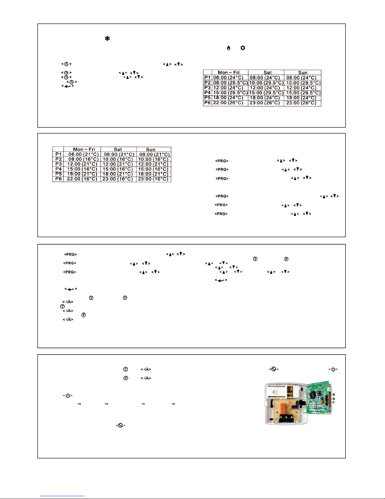
Heater mode:
F, Setting Your Own Program:
Mon to Fri, Sat and Sun are divided into six periods P1 to P6. The time set
for each period is the start time for that period. To set your own program
you should set the period start time and the temperature to be achieved
during that period.
e.g. In the table above P1 starts at 6am Monday and will hold the
temperature at 210C until period 2 (P2) starts at 8am, when the
temperature will be lowered to 160C until period 3 (P3) & the temperature
E, Factory Defined Programs:
The heater/cooler turns on according to the activated program and the
control temperature setting. When the heater/cooler is ON, the program
number and or will appear in the display.
The pre-defined programs are as below:
Cooler mode:
7 8
9
11 12
13 14
will raise to 210C until period 4 (P4). P4 will hold the temperature at 160C
and so on. You can edit the preset times/temperature values by following
the steps below.
1, Press , the hour will flash, Press , to change the hour
setting.
2, Press , the minute will flash, Press , to change the
minute setting.
3, Press , the temperature will flash, Press , to change
the temperature set-point.
Repeat this sequence for P2, P3, P4, P5 & P6 (Mon-Fri)
4, Press , the hour will flash for P1 day 6 (Saturday), Press ,
to change the hour setting.
5, Press , the minute will flash, Press , to change the
minute setting.
6, Press , the temperature will flash, Press , to change
the temperature set-point.
Repeat this sequence for P2, P3, P4, P5 & P6 (Saturday)
10
7, Press , the hour will flash for P1 day 7 (Sunday), Press ,
to change the hour setting.
8, Press , the minute will flash, Press , to change the
minute setting.
9, Press , the temperature will flash, Press , to change
the temperature set-point.
Repeat this sequence for P2, P3, P4, P5 & P6 (Sunday)
10, Press to confirm changes and return to default screen.
Selecting Temporary or Permanent Override Mode:
1, Press to change the mode from normal to Temporary Override.
The icon will be displayed.
2, Press again and the mode changes from Temporary to Permanent
Override mode. Icon will be displayed.
3, Press once more and the mode changes from Permanent Override
back to normal timed operation.
Review and adjust the Override temperature:
1, With the ET4 in Temporary or Permanent override, press
or to display the Override temperature.
2, Press or for 2 seconds, the Override temperature will flash.
3, Release or and then use or to adjust the Override
temperature .
4, Press to exit Override temperature setting.
The ET4 will return to the default screen if no buttons are pressed after
10 seconds.
G, Temporary Override mode:
The Temporary Override mode is maintained until the start of the next
timed period.
Permanent Override mode:
The room temperature will be maintained at the Override temperature
set-point until the Override mode is released.
Releasing Override mode:
1, When the ET4 is in Temporary Override Press twice to return to
normal timed operation.
2, When the ET4 is in Permanent Override Press once to return to
normal timed operation.
H, Control Off / Sleep Mode:
1, Press to select the sleep mode and control off mode. The sequence
is as below:
Normal mode Sleep mode Control Off mode Normal mode ….
2, Press any other button to exit the Control Off / Sleep mode and return to
normal operation.
Sleep Mode:
When the ET4 is in sleep mode the icon is displayed. The ET4 stops
measuring and controlling the temperature. The heater/cooler is turned
off, irrespective of the current setting temperature.
Control Off mode:
When the ET4 is in Sleep mode and icon is displayed, pressing
will put the ET4 into Control Off mode. The LCD display and the
heater / cooler are turned off, irrespective of the current control
temperature setting.
I, Jumper Selection:
Delay / No Delay Jumper
Heater Cooler
No Delay 10sec 4mins
Delay 4mins 4mins
Choose the Delay option if
compressor heat is connected.
12-hour / 24-hour mode jumper:
When the 12-hour option is selected, the time is shown in 12 hour mode.
Otherwise the time is displayed in-24 hour mode.
Heater / Cooler Jumper:
The ET4 can be set for a heating or cooling configuration via internal
jumper.
a = 12/24 hours
b = Delay / No delay
c = Heater / Cooler
3, In heating mode frost protection is activated automatically if the ambient
temperature falls below 50C. Will show in the display and the output
will be forced ON for heating or OFF if the ET4 is configured for cooling.
4, If the ambient temperature is below 00C, “LO” will show in the display.
5, Above 400C, “HI” will show in the display.
D. Setting the real-time clock:
1, Press , the day of week (1-7) will flash 1=Monday. Press ,
To select the current day of the week.
2, Press , the hour will flash, press , to set the hour.
3, Press , the minute will flash, press , to set the minute.
4, Pressing will return back to step 1 (day setting).
5, Press to confirm settings and return to the default screen.
Note: If no buttons are pressed within 10 seconds the ET4 will return to the
default screen

K, Jumper Locations:
J, Jumper Selection:
Delay / No Delay Jumper:
Heater Cooler
No Delay 10sec 4mins
Delay 4mins 4mins
Choose the delay option if compressor heat is connected.
Heater/Cooler Jumper:
Select the heater option (default) when a heater is connected to the
receiver. Select the Cooler option when using the ET4 for a cooling
application, fan cooling etc. Press “reset” (RST) after modifying jumper
selections.
L, Comms Address Setting:
Inside the transmitter and receiver there is a bank of 9 dip switches for
setting a unique address (pairing). The receiver will ignore
communications from transmitters set to a different address. To access
the dip switches it is necessary to open the thermostat and remove the
front cover from the receiver by removing the two crosshead screws on
the rear cover.
15 16
17 18
Transmitter (Tx) dip
Receiver (Rx)
dip switches
The dip switches on both units must
be set identically to communicate.
M, Specification:
1, Temperature Measurement: 00C - 40C
(0.1
0C/step)
2, Accuracy: ±0.50C
3, Temperature Control Range: 50C - 350C
(0.5
0C/step)
4, Terminals: 2.5mm2Cable
5, Electronic Control: Type 2.B action
6, Transmitter Batteries: 2 x 1.5V AAA
Alkalinebatteries
7, Receiver Input Voltage: 240V AC
8, Receiver Output Voltage: 24..240V AC
50/60Hz
10(3)A Max
9, Operating Temperature: 00C - 500C
10, Storage Temperature: 00C - 600C
11, Sensing Element: NTC Thermistor
19 20
N, Terminal Connecting Block Label:
1
2
3
Default jumper settings:
- No Delay
- 24hr clock
- Heating
TFC Group LLP, Tower House, Vale Rise, Tonbridge, Kent TN9 1TB
Other Eco Thermostat manuals


Popular Thermostat manuals by other brands


Charmeg
Charmeg MP-R user manual

dixell
dixell WING XW40LS Installing and operating instructions

Network Thermostat
Network Thermostat NetX X7C-WIFI Installation and programming manual

Radio Thermostat
Radio Thermostat CT80 Operation guide

HAI
HAI Omnistat RC-120 installation manual

Lennox
Lennox iComfort E30 Installation and setup guide

Lux Products
Lux Products PSD011Ba Installation and operating instructions

Computherm
Computherm Q20 operating instructions

Heatmiser
Heatmiser neoStat user manual

Mars
Mars HEAT CONTROLLER IR Wireless Thermostat user manual

LUX
LUX LP0511D user manual

Saswell
Saswell SAS920XWHB-7-S-RF User manual and warranty card