ECOFOREST HV HIDROCOPPER 18 Manual

MANUEL D’INSTALLATION ET MAINTENANCE
MANUAL DE INSTALAÇÃO E MANUTENÇÃO
MANUALE D’INSTALLAZIONE E MANUTENZIONE
INSTALLATION AND MAINTENANCE MANUAL
MANUAL DE INSTALACIÓN Y MANTENIMIENTO
68987
HV
HIDROCOPPER 18
HP
HIDROCOPPER 18 SLIM
HQ
HIDROCOPPER 18 SLIM+
HW
HIDROCOPPER 24
HX
HIDROCOPPER 24 SLIM

1
ADVERTENCIAS / WARNINGS / AVERTISSEMENTS / AVVERTENZE / ADVERTÊNCIAS
PELIGRO EN GENERAL / GENERAL DANGER / DANGER EN GÉNÉRAL
/ PERICOLO
GENERICO / PERIGO EM GERAL
RIESGO ELÉCTRICO / ELECTRICAL HAZARD / RISQUE ÉLECTRIQUE
/ RISCHIO
ELETTRICO / RISCO ELÉTRICO
MATERIAL COMBUSTIBLE / FLAMMABLE MATERIAL /
MATÉRIEL INFLAMMABLE
/ MATERIALE COMBUSTIBILE / MATERIAL COMBUSTÍVEL
SUPERFICIES CALIENTES / HOT SURFACES / SURFACES CHAUDES /
SUPERFICI
CALDE / SUPERFÍCIES QUENTES
AGUA CALIENTE / HOT WATER / EAU CHAUDE / ACQUA CALDA / ÁGUA QUENTE
OBLIGACIONES / OBLIGATIONS / OBLIGATIONS / OBBLIGHI / OBRIGAÇÕES
LEER MANUALES DE INSTRUCCIONES / READ THE INSTRUCTION MANUAL / LIRE
LES MANUELS D'INSTRUCTIONS / LEGGERE I MANUALI DI ISTRUZIONI / LER
MANUAIS DE INSTRUÇÕES
DESCONEXIÓN ELÉCTRICA / ELECTRICAL DISCONNECTION / DÉCONNEXION
ÉLECTRIQUE / DISCONNESSIONE ELETTRICA / DESCONEXÃO ELÉTRICA
USO DE GUANTES / USE OF GLOVES / UTILISATION DE GANTS
/ USO DI GUANTI
/ USO DE LUVAS
PREVENIR RIESGOS DURANTE LA MANIPULACIÓN DE LA CARGA / RISK
PREVENTION WHILE HANDLING CARGO / PRÉVENIR DES RISQUES LORS DES
OPÉRATIONS DE MANUTENTION
/ PREVENIRE I RISCHI NELLA
MOVIMENTAZIONE DEI CARICHI / PREVENIR RISCOS DURANTE O
MANUSEAMENTO DA CARGA
ENCARGADO TAREA Y FRECUENCIA / PERSON IN CHARGE AND FREQUENCY / RESPONSABLE
TACHE ET FRÉQUENCE / ADDETTO COMPITO E FREQUENZA / ENCARREGADO TAREFA E
FREQUÊNCIA
USUARIO / USER / USAGER / UTENTE / USUÁRIO
TÉCNICO / TECHNICIAN / TECHNICIEN / TECNICO / TÉCNICO
DIARIA / DAILY / QUOTIDIEN / GIORNALIERO / DIÁRIO
SEMANAL / WEEKLY / HEBDOMADAIRE / SETTIMANALE/ SEMANAL
ANUAL O CADA 500KG COMBUSTIBLE / ANNUAL OR EVERY 500 KG OF FUEL /
ANNUEL OU CHAQUE 500 KG DE COMBUSTIBLE / ANNUALE OD
OGNI 500 KG DI
COMBUSTIBILE / ANUAL OU A CADA 500KG COMBUSTÍVEL

2
HIDROCOPPER 18 (HV 00-03)
HIDROCOPPER 18 SLIM (HP 00-02)

3
HIDROCOPPER 18 SLIM+ (HQ 00-01)
UNE EN 14785

4
HIDROCOPPER 24 (HW 00-01)
HIDROCOPPER 24 SLIM (HX 00-01)
UNE EN 14785

5
Notas|Notes|Notes|Annotazioni|Anotações
_________________________________________________________
_________________________________________________________
_________________________________________________________
_________________________________________________________
_________________________________________________________
_________________________________________________________
_________________________________________________________
_________________________________________________________
_________________________________________________________
_________________________________________________________
_________________________________________________________
_________________________________________________________
_________________________________________________________
_________________________________________________________
_________________________________________________________
_________________________________________________________
_________________________________________________________
_________________________________________________________
_________________________________________________________
06/05/2021
Español.
Página
6
English.
Page
28
Français .
Page
49
Italiano.
Página
72
Português.
Página
94

28
Read carefully this manual before using the appliance.
Only that
way, the best performance and maximum
safety will be got during its use.
This appliance can be used by children aged from 8
years and above and people with reduced physical,
sensory or mental capabilities or lack of experience
and knowledge if they have been given supervision or
instruction concerning the use of the appliance i
n a
safe way and if they understand the hazards involved.
Children shall not play with the appliance.
Cleaning
and user maintenance
shall not be made by children
without any supervision.
The glass door and some other surface areas of the
appliance may reach high temperatures.
WARNING: Do not open the door while the appliance
is operating.
Pay special attention to pages 2-4 and points 1, 2.20
and 4.
Max. pressure of inlet water: 220 kPa.
Min. pressure of inlet water: 80 kPa.
Recommended water pressure in circuit: 120 kPa.


30
1. TECHNICAL FEATURES.
HIDROCOPPER 18
HIDROCOPPER 24
HV 00-03
SLIM
HP 00-02
SLIM+
HQ 00-01
HW 00-01
SLIM
HX 00-01
CONNECTIONS
Heating return – ring female
“
3/4
3/4
Safety valve discharge – thread
female
“1/2 1/2
Heat flow – thread female
“
3/4
3/4
Charge – Discharge – thread female
“
1/2
1/2
Gas output
mm
100
100
Air entrance
mm
60
60
AIR ADMISSION
Maximum air flow admission*
m3/h
202.8
237.4
Minimum draught recommended
mBar / Pa
10
10
HYDRAULICS
Expansion vessel
8 L | -10/+100 °C
0,75 Bar | 3 Bar máx
Maximum working pressure
Bar / KPa
2,2 / 220
Minimum working pressure
Bar / KPa
0,8 / 80
Recommended working pressure
Bar / KPa
1,2 / 120
Security discharge pressure
Bar / KPa
3 / 300
Water volume inside boiler
L
GENERAL FEATURES
Weight
Kg
133
154
162
171
--
Capacity of the hopper **
Kg
23
36
36
32
40
Noise at level 9, 3 meters in length and 1.5
meters in height
dB 46 46
NOMINAL HEAT OUTPUT
Fuel drop level
1 - 9
9
9
Nominal heat output
kW
18
23,6
Efficiency
%
93
92
Consumption
kg/h
4
5,1
Approximate autonomy
H
6
6
6
6
8
CO content (with O2 levels of 13%)
%
0.02
0,02
Exhaust mass flow
g/s
47
55
Average smoke temperature
°C
150
150
Auxiliary power consumption
W
120
48
REDUCED HEAT OUTPUT
Fuel drop level
1 - 9
1
1
Reduced heat output
kW
9.5
9,5
Efficiency
%
95
94
Consumption
kg/h
2
2
Approximate autonomy
H
12
16
16
16
20
CO content (with O
2
levels of 13%)
%
0.02
0,02
Exhaust mass flow
g/s
31
28
Average smoke temperature
°C
70
90
Auxiliary power consumption
W
35
26
* Estimation according to mass flow and gas temperature in nominal power.
**Fuel estimate
ρ
ap
≈630 kg/m3

31
2. ADVICE AND RECOMMENDATIONS.
2.1. All local regulations, including those referring to national and European standards must be met when installing
the boiler.
2.2. In order to prevent the risk of accident, a correct installation must be done following the instructions of this
manual. Your ECOFOREST distributor will be available to help you and provide you information related to
codes, assembly and installation norms in your area.
2.3. As ECOFOREST do not have direct control on the installation of your stove, ECOFOREST do not guarantee it
and do not bear the responsibility of any damage that could result from a bad use or a bad installation.
2.4. We carefully recommend the heat calculation to be made by a qualified heating engineer.
2.5. We recommend that a confirmed specialist sets up your pellets stove.
2.6. Maintenance work to be carried out at the end of the season or for every 500 kg of fuel burned, as well as any
repairs or equipment modifications, must be performed by authorized personnel.
2.7. The boiler must be installed on floors of sufficient bearing capacity and, if the existing construction does not
allow this, the floor must be adapted and made suitable, for example by fitting a load distribution plate.
2.8. Never use petrol, fuel for lanterns, kerosene nor any similar liquid. Keep this kind of fuel away from your boiler.
2.9. Do not try to turn on your boiler if some glass is broken.
2.10.Make sure the glass door of the fireplace is well closed while the boiler is in operation; also check the cleaning
hatches (if you have touched them).
2.11.Unauthorized modifications are forbidden. Use only spare parts provided by Ecoforest (see exploded view).
2.12.Do not overload the boiler; continuous heating efforts might cause premature aging and damage paint (it is
recommended not to exceed 250°C for gas outlet temperature).
2.13. Do not use the boiler as a burner.
2.14. Consider the configuration of the ANTI-ICING and ANTI-LOCK menus (see user manual). If the stove is not being
used over long periods of time and there is a risk of it freezing, empty the device to avoid breakage.
2.15. To prevent possible electrical shocks, only trained personnel should have access to the sides and the back of
the boiler.
2.16. The hydraulic circuit must always keep open a dissipation circuit greater than 30% of the total installation.
2.17. It is highly advisable to perform regular checks to assess the quality of the water in the system, especially if
more water is being added. If you use a water treatment product, make sure it is compatible with the materials
used in the heating installation. To do so, please contact the product’s manufacturer.
2.18. In order to refill the stove with fuel, the user must open the hopper lid and empty the contents of the fuel tank
carefully, to prevent it from overflowing.
Ensure that the lid is correctly closed after the hopper has been loaded.
In airtight installations, do not open the hopper during operation of the machine.
Drawing 1
2.19. FIRE IN THE EXHAUST. To prevent this situation from happening, observe the instructions set forth under
section 4 on how to install the gas outlet. What to do:
•The appliance will be turned off due to the excessive temperatures in the exhaust. Do not unplug the stove.
•Call fire brigade.
•The stove must be tested by Chimeney’s sweeps after the soot fire, before it is reused.
Hopper lid.
Fuel.
Lock and unlock decorative cover.

32
2.20.The appliance is intended to be permanently connected to water main with a normally closed valve; do not
use a hose-set.
Drawing 2
2.21. Elimination. The stove or boiler cannot be disposed of with household waste when its useful life is over. Please
dispose of the appliance in accordance with the relevant local regulations, in a correct and environmentally
friendly way. Put the product at the end of its useful life in the hands of the waste manager authorized by the
local authorities for transport to a suitable treatment plant.
3. FUEL.
Your stove is designed to operate with wood pellets; however, it can also work with other biomass fuels (ask
your dealer about this). If using a different type of biomass is possible, select it from the fuel selection menu (check
user manual). In most cases, the combustion basket is not the same as for wooden pellets.
ECOFOREST do not have any control on the quality of the fuel you use. For this reason, ECOFOREST cannot
guarantee the full output of your stove nor the eventual premature aging or eventual damage of the gas outlet. The
fuel’s minimum requirements are specified below:
Pellets
Olive pits
Almond shells
Diameter (mm)
6
— —
— —
Length (mm)
5-25
— —
— —
Granulometry (mm)
— —
3 - 4
6 - 8
Calorific value (Kcal/kg)
≥ 4300
≥ 3800
≥ 3700
Ash (% mass)
< 1.5
< 1.5
< 1.5
Humidity (%mass)
< 12
< 12
< 12
Oils
— —
No oil content
— —
Grill and/or specific strangler.
ORIGINAL
SPECIFIC
SPECIFIC
4. INSTALLATION.
The below security distances and assembly diagrams are given for information only as an adaptation shall be
made depending on the norms in force regarding gas outlet, power, security minimum distances specific to geographic
areas.
Air inlets and water connections will be missed in all drawings as section 4.16 indicates the minimum security
distances to be respected for their installation.
ELECTRICAL CONNECTION.
The power socket to which the stove is plugged should meet the following requirements:
4.1. Ground connection must comply with the specific applicable regulations.
4.2. Differential switch with the correct amperage. It must comply with the specific applicable regulations (check
technical specifications of the stove).
Heat flow. (See technical features).
Heating return. (See technical features).
Safety valve discharge. (See technical features).
Charge-discharge. (See technical features).
Drain siphon.
Normally closed valve
Water main.

33
4.3. Single-phase AC of ~230/240V – 50Hz and pure sine wave.
4.4. The plug must only be connected to a socket with the technical characteristics of the plug in question.
4.5. Easily accessible power socket. If the power socket can’t be accessed due to the characteristics of the electrical
installation, an all-pole disconnection switch must be installed.
4.6. The power cable provided by ECOFOREST is 1.4m long; you might need a longer one. Always use a cable with
ground plug and with an equal or greater section. Make sure the power cable is not placed under the stove or
close to hot or sharp surfaces that could damage it.
UNPACKING THE BOILER.
4.7. Remove the packaging and the protective plastic.
4.8. Remove the screws or bolts that fasten the stove to the pallet and remove it.
4.9. If our model has a plastic protection, it must be removed before starting it.
4.10. Remove exhaust blower protection ().
Airtight installation: Remove protection from the air intake pipe ().
Drawing 3
MATERIALS REQUIRED FOR INSTALLATION
MATERIAL
COMPLIANCE
PARTICULARS
It will be made of a material
resistant to the aggressive action
of the combustion products, to
condensation and to constant
temperatures of 300 °C. The
material will comply with the local
legislation for its application.
OBLIGATORY •ALL.
Aluminum, galvanized or iron
pipe.
PROHIBITED •ALL.
Insulated double wall pipe.
OBLIGATORY
•Proximity to flammable materials.
•When crossing a forge or partition.
•
Outdoor or brick-built chimney installation.
RECOMMENDABLE
•Relative ambient humidity ≥ 60%.
•Installation in a public facility.
•
Potentially accessible to children or people with
mental, physical or sensory disabilities.
T with outlet.
OBLIGATORY
•ALL.
Clamp union. OBLIGATORY
•Install the exhaust spiral and gas outlet pipes,
thereby preventing anyone from disassembling or
moving the stove or pipe without tools.

34
Pipe anchors. OBLIGATORY
•Install the pipe, thereby preventing anyone from
disassembling or moving the stove or pipe
without tools.
Aluminium belt and silicone of
high temperature (300°C).
RECOMMENDABLE •If the pipe is not equipped with sealing rings
Pressure gauge. RECOMMENDABLE
•To compare the pressure of the circuit with which
the boiler indicates.
Expansion vessel.OBLIGATORY
•If the stove’s expansion tank is not big enough
according to specific calculations.
Buffer tank.RECOMMENDABLE
•Installation of special features such as radiant
floor, areas operated by thermostatic valves,
other stoves working in the same site, etc. The
device must be fitted with a buffer tank for
proper
regulation.
Electrolytic sleeve. RECOMMENDABLE
•Depending on the material used for the hydraulic
circuit.
Flexible hose for hydraulic
connection resistant to constant
temperatures of 110 °C
RECOMMENDABLE •SLIM and SLIM+ models.
Ventillation grills.
OBLIGATORY
•Insert stoves.
“DIFLUX” piping.
OBLIGATORY
•AIRTIGHT INSTALLATION "DIFLUX" mounting.
LOCATION AND SAFETY DISTANCES.
4.11. Do not install the stove in a sleeping room.
4.12. Install a fire protection between the ground and the stove if the floor is a combustible material.
4.13. Security distances should be respected when the stove is installed in spaces where materials around it, be it
the construction material itself, the fuel or any other type of materials, are likely to be flammable. Ensuring a
better access to the stove for future maintenance or repair work is also worth considering.
Drawing 4
SECURITY NORMS FOR GAS OUTPUT AND AIR INPUT.
4.14. Gas output must be located in a ventilated area, not in closed or half-closed areas e.g. garage, corridor, air
space of the house or places where gas may concentrate.
4.15. The external parts of the stove may reach high temperatures that might burn when touching; it is
recommended to use a non flammable grid to avoid risk of burn for children and old people.
The end of the gas outlet flex should remain higher than the stove’s output. It is mandatory to install at least
two metres in length vertically to create natural current preventing smoke, odors or eventual cut of electric
supply.
The horizontal pipe must not be longer than 1 metre; greater lengths mean ash, condensation or corrosion
may build up in this area.
A
Lateral wall.
≥ E
B
Back of the stove. Minimum separation
that allows visualizing the label
marking the stove.
≥ 80 mm
C
1.5 x depth of stove.
See dimensions
D
Shelf.
≥ 400 mm
E
Depth of stove.
See dimensions
D
B
E
A
35
Faced with cut of electric supplies and unusual weather conditions (storms, strong winds) it is recommendable
to install an uninterruptible power supply (UPS) which we have available as an option. This apparatus only
feeds the exhaust vent.
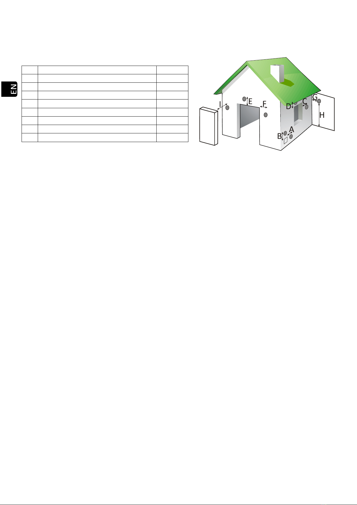
4.16. Distances from doors, Windows, ventilation grids or air input to the house or building:
Drawing 5
4.17. The minimum distance from gas outlet to ground shall be minimum 65cm, depending however on the surface.
Gas may burn grass, plants, trees located near the gas outlet. In the event that the stove outlet is lower, suitable
safety measures should be taken. The outlet pipe should never be below the extractor itself.
4.18. The distance between gas outlet and public pavement shall be minimum 2.20 m. See your local regulations.
4.19. Never fix the gas outlet flex in a chimney or a flex already installed which diameter is 4 times as large as the
stove’s flex (Ø80 max. 200cm2 with flex of Ø100 max. 314 cm2). When installing the stove in higher section the
gas outlet must be channeled to the top.
If the tube that was installed previously was used with another type of heating (wood, oil, etc.), you MUST
clean it thoroughly, to reduce the risk of fire in the gas vent.
4.20. Gas outlet flex cannot be installed in a share pipe such as the pipe of an extractor hood, another stove or
heating system.
4.21. If gas outlet installation is wrong, combustion air’s homogeneity might be bad which could make the wall of
the house or the building dirty, aggregate trash inside the stove and thus be the source of premature
degradation of the spare parts and gas outlet pipe.
4.22. The air input pipe should not be drained with the risk of affecting the correct operation of the stove. For this
reason, and in order to facilitate fresh air input, it is necessary to set up a ventilation grid AT NOT LESS than
50cm both horizontally and vertically from gas output, see point 4.16.
Direct air currents shall also be avoided as they might prevent a correct operation of the stove and as a
consequence, heat performance.
Ventilation of the room must meet the minimum flow required according to specific regulations and the
maximum intake air flow of the machine.
Extraction fans can cause problems when operating in the same room or in the same space as the appliance.
4.23.In any case the design of the chimney termination will impede the free diffusion in the atmosphere of
combustion products. A metallic mesh with a gap of 3x3 cm can be placed to avoid the entry of birds or
unwanted objects.
4.24.If a testing module is installed to collect combustion gas readings and samples, it must be equipped with
hermetic and self-locking sealing.
EXAMPLES OF FLUE INSTALLATIONS.
Although we cannot keep track of or describe every single installation, option, or the local installation
regulations corresponding to your area, Ecoforest guarantees that the installations suggested below will enable
your stove to function properly, and to conform to minimum personal and material safety measures.
If you are installing your stove in a building, in addition to respect local regulations on gas flues, you should
consult with the residents’ association to avoid future problems.
Please read the entire manual carefully, especially the chapter on installation to ensure your stove operates
properly and at full power.
A
Distance from ventilation grid.
500 mm
B
Distance from ventilation grid.
500 mm
C
Lateral side of a window.
1250 mm
D
Top of a window.
650 mm
E
Top of a door.
650 mm
F
Lateral side of a door.
1250 mm
G
Adjacent wall.
300 mm
H
Height from adjacent wall.
2300 mm
I
Adjacent building.
650 mm

36
If the total pipe length exceeds 8m, it is recommended to increase one measure, being able to make the
whole assembly in the same diameter from the connection of the stove or increase section from 4 m.
4.25. The installation shown below is the most common. Please bear in mind that if the gas flue pipe located on the
outside of the dwelling is in an area where people pass by, insulated tube must be used.
Drawing 6
4.26. If for aesthetic, safety or municipal regulations we cannot install the stove as described above, we can always
install the pipe on the inside of the dwelling, paying special attention to the areas where the pipe touches
structures, and the minimum vertical and maximum horizontal lengths.
Drawing 7
4.27. When fitting stoves in brickwork chimneys a perfect seal between the flexible and the rigid pipe must be
achieved. Similarly, the insulation to be placed at the contact areas between the pipe and possibly inflammable
zones must be taken into account. The tube end may be left inside the chimney itself, taking into account its
opening.
Once installation is complete, we must seal the chimney from the inside of the house.
Windbreak.
Stainless steel hose clamp.
T of 135° with outlet.
Insulator.
Wooden ground.
Non flammable floor protection.
Distance equal to or less than 2 metres.
Windbreak.
Stainless steel hose clamp.
T of 90° with outlet.
Insulator.
Wooden ground.
Non flammable floor protection.
Elbow of 135°.
Distance equal to or over 2 metres.
MAXIMUM 1 metre.

37
Drawing 8
4.28. Installing a fitted stove in a brickwork chimney can be done using flexible piping in its entirety, as indicated in
drawing 9. We must take special care when sealing the chimney and gas venting to avoid gas blowing back
during storms.
Drawing 9
When installing a flexible tube for gas outlet be careful that this is not in contact or close to the circuit board
or combustible material.
TOP GAS OUTLET HIDROCOPPER 18 SLIM+
Figura 10
Stainless steel hose clamp.
T of 135° with outlet.
Wooden ground.
Non flammable floor protection.
Isolated stainless steel flexible tube.
Rigid flexible pole adapter.
Minimum 200mm.
It must exceed roof height by 1 metre.
If the tube over 8 m in length, the next larger
size will be used.
Stainless steel hose clamp.
T of 135° with outlet.
Wooden ground.
Non flammable floor protection.
Stainless steel flexible tube.
Rigid flexible pole adapter.
Anti blow-back seal.
Minimum 200mm.
It must exceed roof height by 1 metre.
If the tube over 8 m in length, the next larger
size will be used.

38
EXAMPLES OF AIRTIGHT INSTALLATION.
Reduction of the air intake pipe section and gas output section is strictly forbidden.
Ignore section 4.22 in case of airtight installation.
It must be installed in a room with positive atmospheric pressure (minimum 5 pascals). Never make it
work in depression (airtight rooms or without the due air renovations).
Please note below two kinds of airtight installations:
4.29. “DIFLUX” piping.
The gas outlet and the combustion air inlet are connected to the concentric "Diflux" tube. After the air intake
you will find immediately on the outside, the rest of pipe sections should be in double wall pipe.
Drawing 11
For these installations it is highly advised to modify the depression offset, according to the number of pipe
sections installed. See the following chart:
Gas
outlet pipe sections
Offset adjustment
“Depression” (PA)*
≤ 3m
+ 5.0
4m
+ 8.0
> 4m
+8.0 ≥ Adjustment ≤ +14.0
Drawing 12
*Check modification over the offset with the stove working on level 1 and 9 during 1 hour, controllong the right
combustión of the stove ( no smoke, no depressure excess, etc).
4.30. Air inlet connected directly to the outside.
Air intake pipe.
Combustion air intake.
Gas output >2m. Double wall pipe in the
outside.
Windbreak.
Connection of stove to combustion gas outlet.
Stainless steel hose clamp.

39
Drawing 13
It is highly recommended to place a grid in the intake pipe to allow the free air circulation and avoid the
entrance of unwanted objects or little animals like birds.
HEATING SYSTEM DRAINING (VERY IMPORTANT).
Drawing 14
POWER CABLE, ROOM SENSOR AND WiFi ANTENNA CONNECTION.
An Ecoforest box is placed inside the fireplace. It contains the user manual, the installation and maintenance
manual, a keyboard and keyboard support, a WiFi antenna, a power cable, a room sensor and a cleaning brush. The
keyboard must be mounted with its holder.
Drawing 15
Air intake tube.
Combustion air intake from the outside.
Gas output >2m.
Windbreak.
Stainless steel hose clamp.
Purger.
Keyboard and keyboard support.
Room probe.
Power cable.

40
Screw the WiFi antenna to the docking station. This magnet base must be stuck to the back of the boiler. Once
assembled, the unit has to remain in a vertical position.
Drawing 16
Place the magnet connection base with the antenna where appropriate. When possible, avoid the presence of
metal sheets around the antenna as the WiFi signal might be distorted.
WiFi upper view.
WiFi plan view with no metal objects around.
5. CLEANING AND MAINTENANCE.
To ensure the correct operation of your boiler, the following Cleaning and maintenance operations are
necessary at the indicated frequency. The boiler must always be cold.
The deterioration of the boiler parts by a lack of cleaning involves the loss of the two-year warranty offered by
ECOFOREST (see warranty section).
DAILY CLEANING WHEN THE BOILER IS COLD.
5.1. Heat Exchanger.
Activate the cleaning lever several times. This shall be done while the glass door closed in order to reach the
ash inside the boiler. This shall be done every day when the boiler is cold.
Antenna.
Magnet connection base.

41
Drawing 17
5.2. Burning pot.
Clean the burning pot, check its holes and vacuum the burning pot holder. After cleaning, replace the burning
pot correctly.
Drawing 18
5.3. Fireplace door.
Clean the glass with a towel, using a liquid for glass cleaning, always when cold.
WEEKLY MAINTENANCE.
5.4. Ash box.
Empty the ashtray box and hoover its location.
Drawing 19
IMPORTANT:If the boiler is operating while full of ash or residues, that might stretch the burn pot and its
support, the ashtray basket and even the burn pot, being the cause of bad operation or possible breakdown.
MAINTENANCE AT END OF SEASON OR EVERY 500 KG OF FUEL.
Top.
Cleaning lever.
Ash box.
This manual suits for next models
4
Table of contents
Other ECOFOREST Stove manuals


Popular Stove manuals by other brands


Morso
Morso 8100 series instruction manual

FAIR
FAIR BIO80 manual

Lokaterm
Lokaterm KOMEN Installation instruction

Wood Pellet Products
Wood Pellet Products Gravity Grill owner's manual

Quadra-Fire
Quadra-Fire GARN-DMBK-IPI-B installation manual

Charnwood
Charnwood Island 1 Operating & installation instructions


