ECOFOREST MIAMI Manual


27
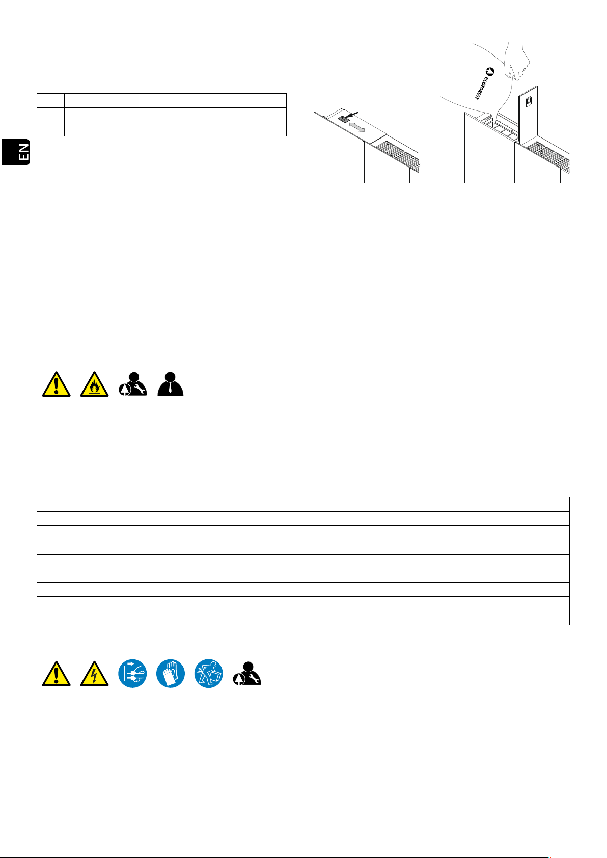
WARNINGS
GENERAL DANGER
ELECTRICAL HAZARD
FLAMMABLE MATERIAL
HOT SURFACES
OBLIGATIONS
READ THE INSTRUCTION MANUAL
ELECTRICAL DISCONNECTION
USE OF GLOVES
RISK PREVENTION WHILE HANDLING CARGO
PERSON IN CHARGE AND FREQUENCY
USER
TECHNICIAN
DAILY
WEEKLY
ANNUAL OR EVERY 500 KG OF FUEL

28
Read carefully this manual before using the appliance.
Only that way, the best performance and maximum
safety will be got during its use.
This appliance can be used by children aged from 8
years and above and people with reduced physical,
sensory or mental capabilities or lack of experience
and knowledge if they have been given supervision or
instruction concerning the use of the appliance in a
safe way and if they understand the hazards involved.
Children shall not play with the appliance. Cleaning
and user maintenance shall not be made by children
without any supervision.
The glass door and some other surface areas of the
appliance may reach high temperatures.
WARNING: Do not open the door while the appliance
is operating.
Pay special attention to points 1 and 4.

29
INDEX
1.
TECHNICAL FEATURES.
Page
30
1.1.
MIAMI DIMENSIONS (PC).
Page
30
1.2.
CRETA DIMENSIONS (LF).
Page
30
1.3.
MOON II DIMENSIONS (VS).
Page
31
1.4.
VIGO III DIMENSIONS (NW).
Page
31
1.5.
KEOPS DIMENSIONS (KP).
Page
32
1.6.
STOVES DATA.
Page
33
2.-
ADVICE AND RECOMMENDATIONS.
Page
34
3.-
FUEL.
Page
35
4.-
INSTALLATION.
Page
35
5.-
CLEANING AND MAINTENANCE.
Page
42
6.-
PROBLEMS AND RECOMMENDATIONS.
Page
46
7.-
WARRANTY.
Page
49
8.-
ELECTRICAL DRAWING.
Page
179

30
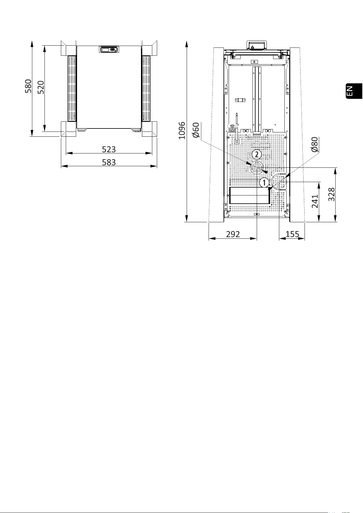
1. TECHNICAL FEATURES.
1.1. MIAMI DIMENSIONS (PC).
1.2. CRETA DIMENSIONS (LF).
760
500
99
182 Ø80
455
760
227
169 Ø60
594
680
784
818
20
165 708
828
247
105
708
950
80
Ø80
Ø30
Ø100 Ø80
80
R8 289 310

31
1.3. MOON II DIMENSIONS (VS).
1.4. VIGO III DIMENSIONS (NW).
91
218 Ø80
455
227
1033
304 Ø60
892
99
182 Ø80
455
502
227
165 Ø60
32
1.5. COTAS KEOPS (KP).
33
1.6. STOVES DATA.
MIAMI
PC
CRETA
LF
MOON II
VS
VIGO III
NW
KEOPS
KP
CONNECTIONS
Gas output Ø
mm
80
80
80
80
80
Air imput airtight pipe Ø
mm
30
60
60
60
60
Convection air duct Ø
mm
100
- -
- -
- -
--
AIR ADMISSION
Maximum air flow admission*
m3/h
26
26
26,8
36,2
36,2
Minimum draught recommended
mBar
0,10
0,10
0,10
0,10
0,10
Pa
10
10
10
10
10
GENERAL FEATURES
Weight
Kg
77
71,5
89
91
111
Operate with wood pellets
A1
Si
Si
Si
Si
Si
Hopper capacity **
Kg
7
11
15
16
16
Safety thermostat tared
°C
125
125
125
125
125
Noise at level 9, 3 meters in length and 1.5 meters in
height.
dB
40,5
40,5
48,5
42,5
42,5
NOMINAL HEAT OUTPUT
Fuel drop level
1 - 9
9
9
9
9
9
Nominal heat output
kW
5,5
6
7,5
9,5
9,5
Efficiency
%
88,5
85
89
88,8
88,8
Consumption
kg/h
1,2
1,4
1,7
2,1
2,1
Approximate autonomy
h
6
8
8,9
7
7
CO content (with O2 levels of 13%)
%
0,02
0,02
0,02
0,02
0,02
mg/Nm3
238
225
225
205
205
NOx.
mg/Nm3
199
198
190
185
185
OGC.
mg/Nm3
40
15
15
5
5
PM.
mg/Nm3
20
19
20
18
18
Exhaust mass flow
g/s
6
6
6
8
8
Tª media de los humos
°C
151
151
165
171
171
Auxiliary power consumption
W
85
60
85
179
179
Flow and average temperature of conducted air
m3/h
19,79
- -
- -
- -
- -
°C
70
- -
- -
- -
- -
REDUCED HEAT OUTPUT
Fuel drop level
1 - 9
1
1
1
1
1
Reduced heat output
kW
3
3
2,5
3,1
3,1
Efficiency
%
91,2
91,2
94
91,8
91,8
Consumption
kg/h
0,7
0,7
0,5
0,6
0,7
Approximate autonomy
h
11
17
28
26
24
CO content (with O2 levels of 13%)
%
0,02
0,02
0,02
0,02
0,02
mg/Nm3
297
245
250
240
240
NOx.
mg/Nm3
198
198
190
198
198
OGC.
mg/Nm3
41
18
20
15
15
PM.
mg/Nm3
20
20
20
20
20
Exhaust mass flow
g/s
4
4
11
5
5
Tª media de los humos
°C
87
87
100
76
76
Auxiliary power consumption
W
45
25
30
88
88
Space heating seasonal energy efficiency (ŋs).
%
83,8
84,9
85,4
83,9
83,9
* Estimation according to mass flow and gas temperature in nominal power
** Fuel estimate.
ρap≈630 kg/m3
UNE EN 14785

34
2. ADVICE AND RECOMMENDATIONS.
2.1. All local regulations, including those referring to national and European standards must be met when installing
the boiler.
2.2. In order to prevent the risk of accident, a correct installation must be done following the instructions of this
manual. Your ECOFOREST distributor will be available to help you and provide you information related to
codes, assembly and installation norms in your area.
2.3. As ECOFOREST do not have direct control on the installation of your stove, ECOFOREST do not guarantee it
and do not bear the responsibility of any damage that could result from a bad use or a bad installation.
2.4. We carefully recommend the heat calculation to be made by a qualified heating engineer.
2.5. We recommend that a confirmed specialist sets up your pellets stove.
2.6. Maintenance work to be carried out at the end of the season or for every 500 kg of fuel burned, as well as any
repairs or equipment modifications, must be performed by authorized personnel.
2.7. The stove must be installed on floors of sufficient bearing capacity and, if the existing construction does not
allow this, the floor must be adapted and made suitable, for example by fitting a load distribution plate.
2.8.Never use petrol, fuel for lanterns, kerosene nor any similar liquid. Keep this kind of fuel away from your stove.
2.9. Do not try to turn on your stove if some glass is broken.
2.10.Make sure the glass door of the fireplace is well closed while the boiler is in operation; also check the cleaning
hatches (if you have touched them).
2.11.Unauthorized modifications are forbidden. Use only spare parts provided by Ecoforest (see exploded view).
2.12.Do not overload the stove; continuous heating efforts might cause premature aging and damage paint (it is
recommended not to exceed 250°C for gas outlet temperature).
2.13. Do not use the stove as a burner.
2.14.To prevent possible electrical shocks, only trained personnel should have access to the sides and the back of
the stove.
2.15. The air-convection trim cover must be open whenever the stove is operational.
Drawing 1
2.16. In order to refill the stove with fuel, the user must open the hopper lid and empty the contents of the fuel tank
carefully, to prevent it from overflowing.
Ensure that the lid is correctly closed after the hopper has been loaded.
Do not open the hopper during operation of the machine.
Drawing 2
Air-convection trim cover.
Decorative top.
Fuel.
Hopper lid.
35
Drawing 3
2.17. FIRE IN THE EXHAUST. To prevent this situation from happening, observe the instructions set forth under
section 4 on how to install the gas outlet. What to do:
•The appliance will be turned off due to the excessive temperatures in the exhaust. Do not unplug the stove.
•Call fire brigade.
•The stove must be tested by Chimeney’s sweeps after the soot fire, before it is reused.
2.18. Elimination. The stove or boiler cannot be disposed of with household waste when its useful life is over. Please
dispose of the appliance in accordance with the relevant local regulations, in a correct and environmentally
friendly way. Put the product at the end of its useful life in the hands of the waste manager authorized by the
local authorities for transport to a suitable treatment plant.
3. FUEL.
Your stove is designed to operate with wood pellets A1 quality; however, it can also work with other biomass
fuels (ask your dealer about this). If using a different type of biomass is possible, select it from the fuel selection menu
(check user manual). In most cases, the combustion basket is not the same as for wooden pellets.
ECOFOREST do not have any control on the quality of the fuel you use. For this reason, ECOFOREST cannot
guarantee the full output of your stove nor the eventual premature aging or eventual damage of the gas outlet. The
fuel’s minimum requirements are specified below:
Pellets
Olive pits
Almond shells
Diameter (mm)
6
——
——
Length (mm)
5-25
——
——
Granulometry (mm)
——
3 - 4
6 - 8
Calorific value (Kcal/kg)
≥ 4300
≥ 3800
≥ 3700
Ash (% mass)
< 1.5
< 1.5
< 1.5
Humidity (%mass)
< 12
< 12
< 12
Oils
——
No oil content
——
Grill and/or specific strangler.
Original
Specific
Specific
4. INSTALLATION.
The below security distances and assembly diagrams are given for information only as an adaptation shall be
made depending on the norms in force regarding gas outlet, power, security minimum distances specific to geographic
areas.
The installation of the stoves must be done in the same way, for this reason, only the Creta model will be
exposed. In the same way, air inlets will be missed in all drawings as section 4.16 indicates the minimum security
distances to be respected for their installation.
ELECTRICAL CONNECTION.
Watertight seal.
Fuel.
Hopper lid.

36
The power socket to which the stove is plugged should meet the following requirements:
4.1. Ground connection must comply with the specific applicable regulations.
4.2. Differential switch with the correct amperage. It must comply with the specific applicable regulations (check
technical specifications of the stove).
4.3. Single-phase AC of ~230/240V –50Hz and pure sine wave.
4.4. The plug must only be connected to a socket with the technical characteristics of the plug in question.
4.5. Easily accessible power socket. If the power socket can’t be accessed due to the characteristics of the electrical
installation, an all-pole disconnection switch must be installed.
4.6. The power cable provided by ECOFOREST is 1.4m long; you might need a longer one. Always use a cable with
ground plug and with an equal or greater section. Make sure the power cable is not placed under the stove or
close to hot or sharp surfaces that could damage it.
UNPACKING THE BOILER.
4.7. Remove the packaging and the protective plastic.
4.8. Remove the screws or bolts that fasten the stove to the pallet and remove it.
4.9. If our model has a plastic protection, it must be removed before starting it.
4.10. Remove exhaust blower protection ().
To connect the gas exhaust pipe to the upper outlet on the Miami model, open the door and remove the nut
that secures the lid.
Airtight installation: Remove protection from the air intake pipe ().
Drawing 4
MATERIALS REQUIRED FOR INSTALLATION.
MATERIAL
COMPLIANCE
PARTICULARS
It will be made of a material
resistant to the aggressive action
of the combustion products, to
condensation and to constant
temperatures of 300 °C. The
material will comply with the local
legislation for its application.
OBLIGATORY
•ALL.
Aluminum, galvanized or iron
pipe.
PROHIBITED
•ALL.
Insulated double wall pipe.
OBLIGATORY
•Proximity to flammable materials.
•When crossing a forge or partition.
•External section or built in chimney.
RECOMMENDABLE
•Relative ambient humidity ≥ 60%.
•Installation in a public facility.
•Potentially accessible to children or people with
mental, physical or sensory disabilities.
T with outlet.
OBLIGATORY
•ALL.
37
Clamp union.
OBLIGATORY
•Install the exhaust spiral and gas outlet pipes,
thereby preventing anyone from disassembling or
moving the stove or pipe without tools.
Pipe anchors.
OBLIGATORY
•Install the pipe, thereby preventing anyone from
disassembling or moving the stove or pipe
without tools.
Aluminium belt and silicone of
high temperature (300°C).
RECOMMENDABLE
•If the pipe is not equipped with sealing rings
“DIFLUX” piping
OBLIGATORY
•AIRTIGHT INSTALLATION. "DIFLUX" mounting.
Silicone tube Ø 60mm.
OBLIGATORY
•AIRTIGHT INSTALLATION. "DIFLUX" mounting and
direct connection to the outside. Air intake pipe
connection. (MAX 1m).
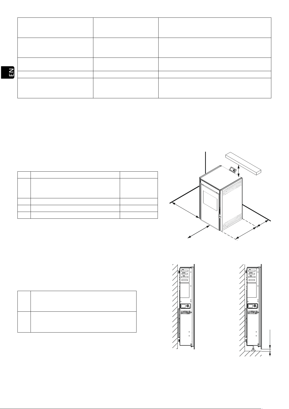
LOCATION AND SAFETY DISTANCES.
4.11. Do not install the stove in a sleeping room.
4.12. Install a fire protection between the ground and the stove if the floor is a combustible material.
4.13. Security distances should be respected when the stove is installed in spaces where materials around it, be it
the construction material itself, the fuel or any other type of materials, are likely to be flammable. Ensuring a
better access to the stove for future maintenance or repair work is also worth considering.
Drawing 5
FIXING OF MIAMI MODEL TO THE WALL.
Drawing 6
A
Lateral wall.
≥ E
B
Back of the stove. Minimum separation
that allows visualizing the label marking
the stove.
≥ 80 mm
C
1.5 x depth of stove.
See dimensions
D
Shelf.
≥ 500 mm
E
Depth of stove.
See dimensions
Wall-mounted stove installation.
Bolts, nuts and washers. M10 minimum.
Remove legs.
Floor-mounted stove installation.
Bolts, nuts and washers. M10 minimum.
Adjust legs.
B
C
D
E
A
20 Mín.
38
SECURITY NORMS FOR GAS OUTPUT AND AIR INPUT.
4.14. Gas output must be located in a ventilated area, not in closed or half-closed areas e.g. garage, corridor, air
space of the house or places where gas may concentrate.
4.15. The external parts of the stove may reach high temperatures that might burn when touching; it is
recommended to use a non flammable grid to avoid risk of burn for children and old people.
The end of the gas outlet flex should remain higher than the stove’s output. It is mandatory to install at least
two metres in length vertically to create natural current preventing smoke, odors or eventual cut of electric
supply.
The horizontal pipe must not be longer than 1 metre;greater lengths mean ash, condensation or corrosion
may build up in this area.
Faced with cut of electric supplies and unusual weather conditions (storms, strong winds) it is recommendable
to install an uninterruptible power supply (UPS) which we have available as an option. This apparatus only
feeds the exhaust vent.
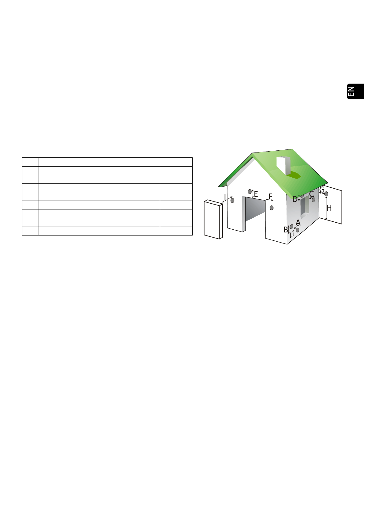
4.16. Distances from doors, Windows, ventilation grids or air input to the house or building:
Drawing 7
4.17. The minimum distance from gas outlet to ground shall be minimum 65cm, depending however on the surface.
Gas may burn grass, plants, trees located near the gas outlet. In the event that the stove outlet is lower, suitable
safety measures should be taken. The outlet pipe should never be below the extractor itself.
4.18. The distance between gas outlet and public pavement shall be minimum 2.20 m. See your local regulations.
4.19.Never fix the gas outlet flex in a chimney or a flex already installed which diameter is 4 times as large as the
stove’s flex (Ø80 max. 200 cm2). When installing the stove in higher section the gas outlet must be channeled
to the top.
If the tube that was installed previously was used with another type of heating (wood, oil, etc.), you MUST
clean it thoroughly, to reduce the risk of fire in the gas vent.
4.20. Gas outlet flex cannot be installed in a share pipe such as the pipe of an extractor hood, another stove or
heating system.
4.21. If gas outlet installation is wrong, combustion air’s homogeneity might be bad which could make the wall of
the house or the building dirty, aggregate trash inside the stove and thus be the source of premature
degradation of the spare parts and gas outlet pipe.
4.22. The air input pipe should not be drained with the risk of affecting the correct operation of the stove. For this
reason, and in order to facilitate fresh air input, it is necessary to set up a ventilation grid AT NOT LESS than
50cm both horizontally and vertically from gas output, see point 4.16.
Direct air currents shall also be avoided as they might prevent a correct operation of the stove and as a
consequence, heat performance.
Ventilation of the room must meet the minimum flow required according to specific regulations and the
maximum intake air flow of the machine.
Extraction fans can cause problems when operating in the same room or in the same space as the appliance.
4.23. In any case the design of the chimney termination will impede the free diffusion in the atmosphere of
combustion products. A metallic mesh with a gap of 3x3 cm can be placed to avoid the entry of birds or
unwanted objects.
4.24. If a testing module is installed to collect combustion gas readings and samples, it must be equipped with
hermetic and self-locking sealing.
A
Distance from ventilation grid.
500 mm
B
Distance from ventilation grid.
500 mm
C
Lateral side of a window.
1250 mm
D
Top of a window.
650 mm
E
Top of a door.
650 mm
F
Lateral side of a door.
1250 mm
G
Adjacent wall.
300 mm
H
Height from adjacent wall.
2300 mm
I
Adjacent building.
650 mm

39
EXAMPLES OF FLUE INSTALLATIONS.
Although we cannot keep track of or describe every single installation, option, or the local installation
regulations corresponding to your area, Ecoforest guarantees that the installations suggested below will enable
your stove to function properly, and to conform to minimum personal and material safety measures.
If you are installing your stove in a building, in addition to respect local regulations on gas flues, you should
consult with the residents’ association to avoid future problems.
Please read the entire manual carefully, especially the chapter on installation to ensure your stove operates
properly and at full power.
If the total pipe length exceeds 8m, it is recommended to increase one measure, being able to make the
whole assembly in the same diameter from the connection of the stove or increase section from 4 m.
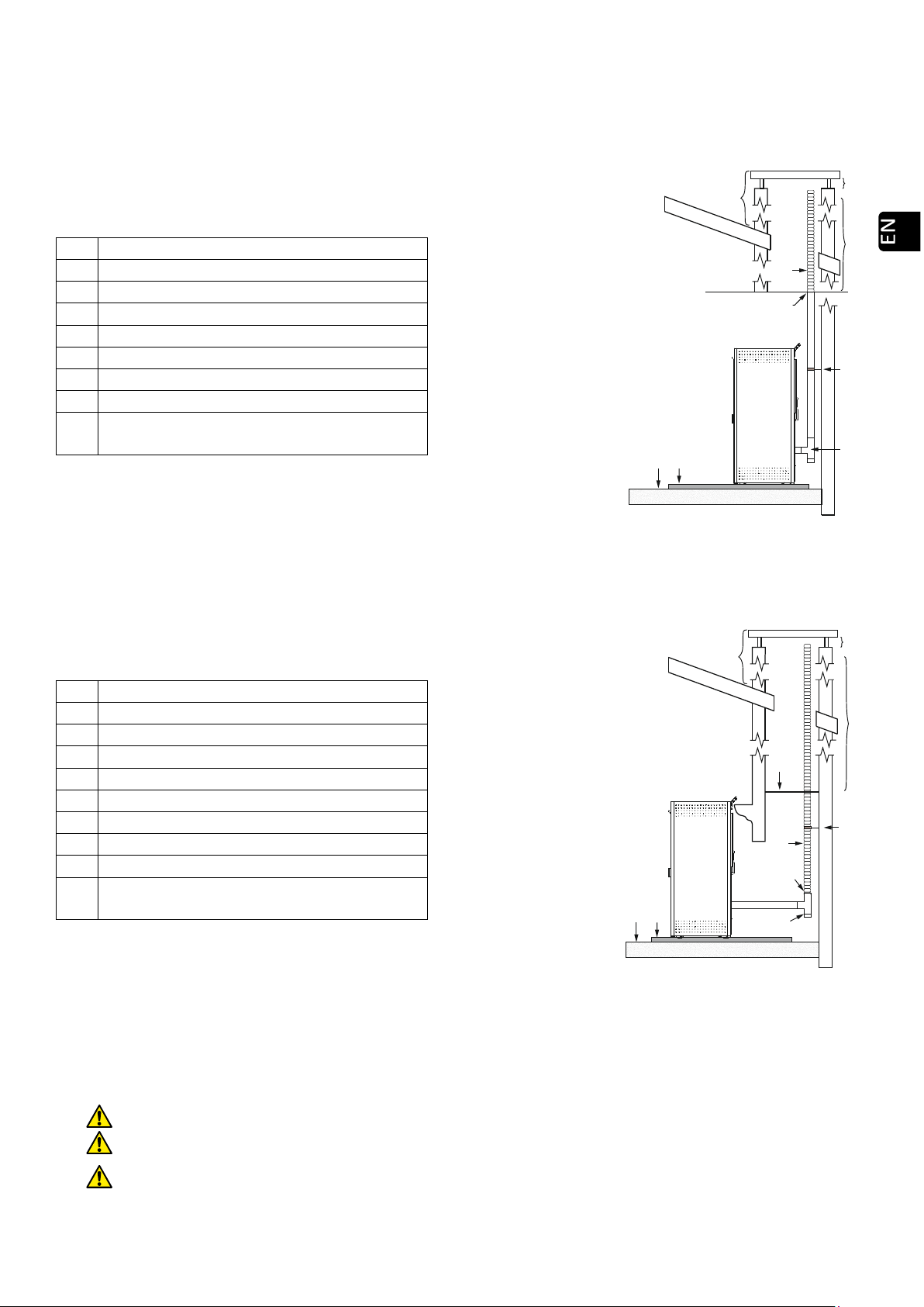
4.25. The installation shown below is the one recommended by Ecoforest to get the best machine performance. The
pipe section will run at least 2 meters vertically through the interior of the house.
Drawing 8
Other installations are possible as well (please check with your authorised dealer.) Other possibilities are added
herebelow:
4.26. Outdoor pipe. Take into account the installation of double wall piping.
Drawing 9
Windbreak.
Stainless steel hose clamp.
T of 90° with outlet.
Insulator.
Wooden ground.
Non flammable floor protection.
Elbow of 90°.
*Distance equal to or over 2 metres.
MAXIMUM 1 metre.
Windbreak.
Stainless steel hose clamp.
T of 90° with outlet.
Insulator.
Wooden ground.
Non flammable floor protection.
*Distance equal to or less than 2 metres.
40
4.27. When fitting stoves in brickwork chimneys a perfect seal between the flexible and the rigid pipe must be
achieved. Similarly, the insulation to be placed at the contact areas between the pipe and possibly inflammable
zones must be taken into account. The tube end may be left inside the chimney itself, taking into account its
opening.
Once installation is complete, we must seal the chimney from the inside of the house.
Drawing 10
4.28. Installing a fitted stove in a brickwork chimney can be done using flexible piping in its entirety, as indicated in
drawing 11. We must take special care when sealing the chimney and gas venting to avoid gas blowing back
during storms.
Drawing 11
When installing a flexible tube for gas outlet, be careful that this is not in contact or close to the circuit board
or combustible material.
EXAMPLES OF AIRTIGHT INSTALLATION.
Reduction of the air intake pipe section and gas output section is strictly forbidden.
Ignore section 4.22 in case of airtight installation.
It must be installed in a room with positive atmospheric pressure (minimum 5 pascals). Never make it
work in depression (airtight rooms or without the due air renovations).
Stainless steel hose clamp.
T of 90° with outlet.
Wooden ground.
Non flammable floor protection.
Isolated stainless steel flexible tube.
Rigid flexible pole adapter.
Minimum 200mm.
It must exceed roof height by 1 metre.
If the tube over 8 m in length, the next larger
size will be used.
Stainless steel hose clamp.
T of 90° with outlet.
Wooden ground.
Non flammable floor protection.
Stainless steel flexible tube.
Rigid flexible pole adapter.
Anti blow-back seal.
Minimum 200mm.
It must exceed roof height by 1 metre.
If the tube over 8 m in length, the next larger
size will be used.

41
In all airtight installations, the depression must be adjusted in the offset menu to at least +10 Pa. This
value may be adjusted according to the particularities of the installation and the value modification
must be carried out by a qualified technician.
Drawing 12
*Check modification over the offset with the stove working on level 1 and 9 during 1 hour, controllong the right
combustión of the stove ( no smoke, no depressure excess, etc).
Please note below two kinds of airtight installations:
4.29. “DIFLUX” piping.
The gas outlet and the combustion air inlet are connected to the concentric "Diflux" tube. After the air intake
you will find immediately on the outside, the rest of pipe sections should be in double wall pipe.
Drawing 13
4.30. Air inlet connected directly to the outside.
Drawing 14
Air intake pipe.
Combustion air intake.
Gas output >2m. Double wall pipe in the
outside.
Windbreak.
Connection of stove to combustion gas outlet.
Stainless steel hose clamp.
Air intake tube.
Combustion air intake from the outside.
Gas output >2m.
Windbreak.
Stainless steel hose clamp.
42
It is highly recommended to place a grid in the intake pipe to allow the free air circulation and avoid the
entrance of unwanted objects or little animals like birds.
POWER CABLE, ROOM SENSOR AND WiFi ANTENNA CONNECTION.
An Ecoforest box is placed inside the fireplace. It contains the user manual, the installation and maintenance
manual, a keyboard and keyboard support, a WiFi antenna, a power cable, a room sensor and a cleaning brush.
Drawing 15
Screw the Wi-Fi antenna to the docking station. This magnet base must be stuck to the back of the boiler. Once
assembled, the unit has to remain in a vertical position.
Drawing 16
Place the magnet connection base with the antenna where appropriate. When possible, avoid the presence of
metal sheets around the antenna as the WiFi signal might be distorted.
WiFi upper view.
WiFi plan view with no metal objects around.
5. CLEANING AND MAINTENANCE.
To ensure the correct operation of your stove, the following Cleaning and maintenance operations are
necessary at the indicated frequency. The stove must always be cold.
Keyboard.
Keyboard support.
Ambient probe connection.
Power connection ~230/240V - 50Hz.
Antenna.
Magnet connection base.

43
The deterioration of the stove parts by a lack of cleaning involves the loss of the two-year warranty offered by
ECOFOREST (see warranty section).
DAILY CLEANING WHEN THE STOVE IS COLD.
5.1. Burning pot & Burning pot holder.
Clean the burning pot, check its holes and vacuum the burning pot holder. After cleaning, replace the burning
pot correctly.
Drawing 17
5.2. Fireplace door.
Clean the glass with a towel, using a liquid for glass cleaning, always when cold.
WEEKLY MAINTENANCE.
5.3. Ash box.
Empty the ashtray box and hoover its location.
Ash box.
Drawing 18
Ash box.
Drawing 19
5.4.Top plate of the fireplace.
You have to push up the top plate of the fireplace (), to disengage the tabs which secure it to the center plate
and pull it. When finished, put back the top plate being sure that the tabs are properly seated.
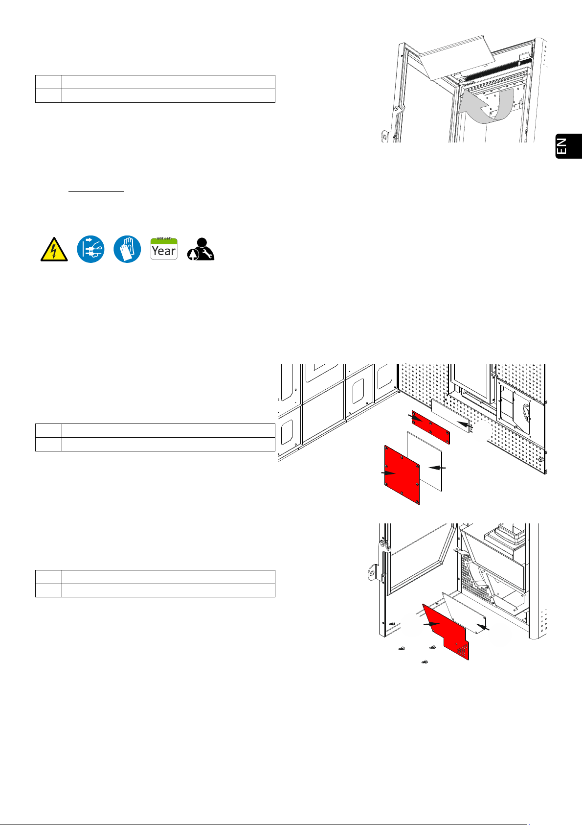
44
Drawing 20
IMPORTANT: If the stove is operating while full of ash or residues, that might stretch the burn pot and its
support, the ash box and even the burn pot, being the cause of bad operation or possible breakdown.
MAINTENANCE AT END OF SEASON OR EVERY 500 KG OF FUEL.
This is necessary to ensure correct operation and maintain the stove’s life duration. When winter ends, contact
your provider (if he did not contact you) and meet to carry out this maintenance; the following shall be done (the stove
must always be disconnected from power):
5.5.Review of the daily and weekly maintenances.
5.6. Cleaning outlets. The cleaning outlet lids are marked in red.
Cleaning record cover.
Ceramic fiber joint. (Replace).
Drawing 21
Cleaning record cover.
Ceramic fiber joint. (Replace).
Drawing 22
It is recommendable to calculate the frequency with which you clean the outlet cleaning considering the hours
of operation, thus avoiding ash saturation.
Once you clean the walls of the stove, you must be sure that the cleaning outlet is securely closed, since the
proper operation of the stove depends on this cleaning.
5.7. Cleaning of the exhaust circuit of the stove, extractor’s collector.
Top plate of the fireplace.
Heat exchanger.
45
For an optimal cleaning of the extractor’s collector, it is recommended to dismantle the extractor itself in order
to have full access to this zone for a better cleaning. Once the extractor is dismantled, clean it with a dry brush
and be careful with the turbine and structure.
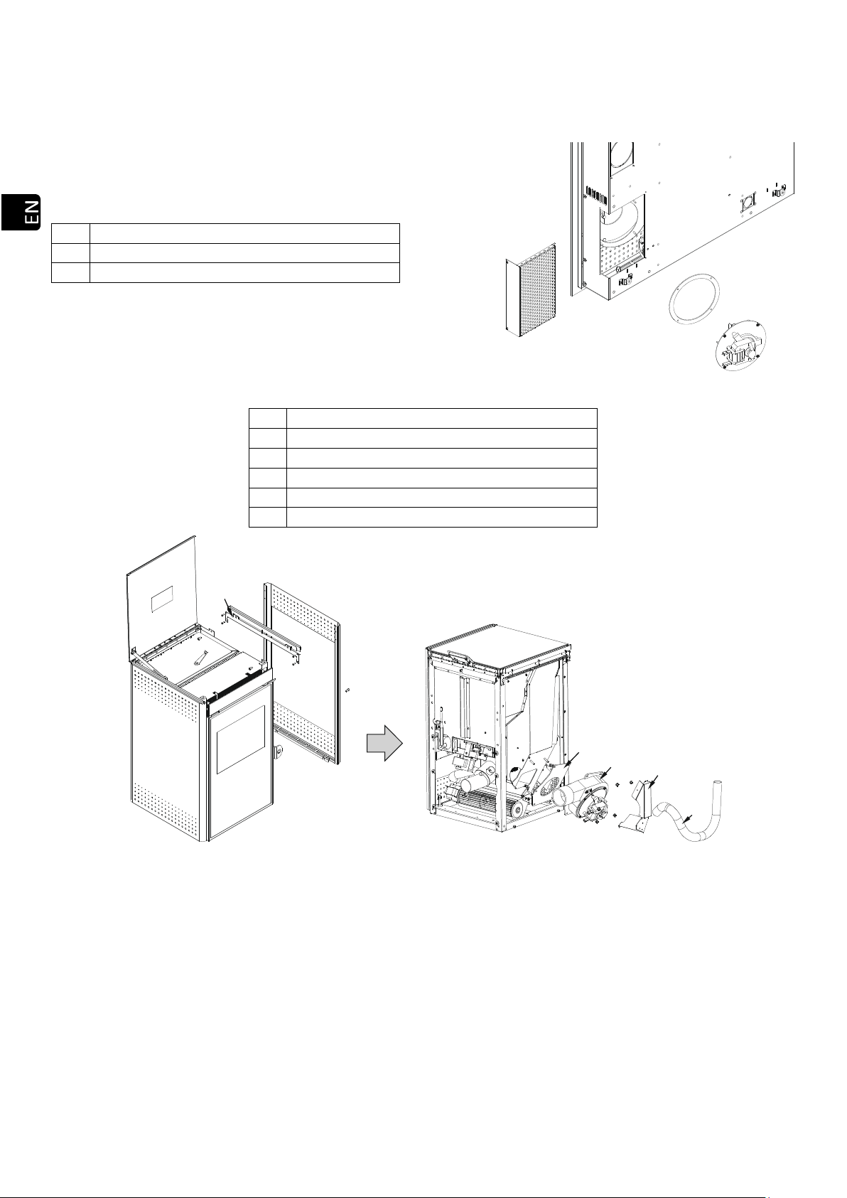
Miami:
Rear protection grid.
Ceramic fiber joint. (Replace).
Exhaust gas extractor.
Drawing 23
Lateral door support.
Right side door.
Ceramic fiber joint (replace).
Exhaust gas extractor.
Back convection chamber plate.
Glass cleaning airtight tube.
Drawing 24
When reassembling the exhaust it is COMPULSORY to replace the exhaust joint with a new one as you run the
risk of gas entering in our home.
5.8. Dismantling and Cleaning of gas outlet pipes.
When mounting the gas outlet pipeline, make sure it is well assembled, preferably sealed with silicone. If the
pipe has sealing joints, you must verify its good condition and replace it if necessary.
5.9. Lubrication of the brass tips of the endless shaft’s upper and lower parts with lubricant oil; a small quantity is
enough for all the season. This operation is only recommended in the case of noise.
You get access to the lower tip from inside the hopper, you will see it clearly after removing all pellets.
In order to reach the upper tip, you have to dismantle the endless screw from the back side of the stove; this
shall be necessary only in case of noise as it has been lubricated at manufacturing, with a high quality lubricant
sufficient for many years.
Other manuals for MIAMI
1
This manual suits for next models
4
Table of contents
Other ECOFOREST Stove manuals


Popular Stove manuals by other brands


ADURO
ADURO P5 Series Technical maintenance manual

BELL TENT VILLAGE
BELL TENT VILLAGE BTV 7K Installation

ACR STOVES
ACR STOVES NOVUS Technical manual

Salamander Stoves
Salamander Stoves Hobbit 0901 Installation and operating instructions

Quadra-Fire
Quadra-Fire CASTILE-CE-MBK owner's manual

Blaze King
Blaze King KING KEJ1107 Owner's installation and operation manual