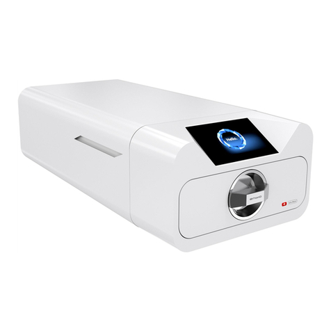
Ecom DK50 User manual


DK50
04/2015 - 1 - NP-DK50 simple s DE-2_04-2015
CONTENTS................................. 2
СОДЕРЖАНИЕ.......................... 15
INHALT....................................... 29
OBSAH........................................ 42
Ed. - 2

DK50
NP-DK50 simple s DE-2_04-2015 - 2 - 4/2015
CONTENTS
IMPORTANT INFORMATION................................................................................................................. 3
1. CE MARKING ............................................................................................................................ 3
2. WARNINGS ................................................................................................................................ 3
3. ALERT NOTICES AND SYMBOLS ............................................................................................ 4
4. STORAGE AND TRANSPORT .................................................................................................. 4
5. TECHNICAL DATA..................................................................................................................... 5
6. PRODUCT DESCRIPTION ........................................................................................................ 6
7. FUNCTION ................................................................................................................................. 6
INSTALLATION....................................................................................................................................... 8
8. USE............................................................................................................................................. 8
9. INSTALLATION .......................................................................................................................... 8
10. WIRING DIAGRAMS ................................................................................................................. 9
11. FIRST OPERATION ................................................................................................................. 11
OPERATION.......................................................................................................................................... 11
12. SWITCHING THE COMPRESSOR ON ................................................................................... 11
MAINTENANCE .................................................................................................................................... 12
13. MAINTENANCE SCHEDULE................................................................................................. 12
14. MAINTENANCE........................................................................................................................ 12
15. STORAGE ................................................................................................................................ 13
16. DISPOSING OF THE APPLIANCE .......................................................................................... 14
17. REPAIR SERVICE.................................................................................................................... 14
18. SOLVING PROBLEMS.............................................................................................................14
PARTS LIST.......................................................................................................................................... 55

DK50
04/2015 - 3 - NP-DK50 simple s DE-2_04-2015
IMPORTANT INFORMATION
1. CE MARKING
Products labeled with the CE mark of compliance meet the safety guidelines (93/42/EEC) of the European
Union.
2. WARNINGS
2.1. General warnings
This Installation, Operation and Maintenance Manual is a part of the appliance and must be kept with the
compressor. Careful review of this manual will provide the information necessary for correct operation of
the appliance.
The safety of operating personnel and trouble-free operation of the appliance are guaranteed only if
original parts are used. Only accessories and parts mentioned in the technical documentation or expressly
approved by the manufacturer can be used.
If any other accessories or consumable materials are used, the manufacturer cannot be held responsible
for the safe operation of the appliance. This guarantee does not cover damages originating from the use
of accessories or consumable material other than those specified or suggested by the manufacturer.
The manufacturer guarantees the safety, reliability and function of the appliance only if:
- Installation, new settings, amendments, extensions and repairs are performed by the manufacturer or
its representative, or a service provider authorized by the manufacturer
- The appliance is used in accordance with this Installation, Operation and Maintenance Manual
The manufacturer reserves all rights for the protection of its wiring diagrams, methods and names.
Translation of Manual for Installation, Operation and Maintenance is carried out in accordance with the
best knowledge. In the case of ambiguities, the Slovak version of the text prevails.
2.2. General safety warnings
The manufacturer developed and designed the equipment in such a way so that any risks were excluded if it
is used according to intention. The manufacturer considers it to be its obligation to describe the following
safety measures in order to exclude residual damages.
Operation of the appliance must be in compliance with all local codes and regulations.
Original packaging should be kept for the return of the appliance. Only the original packaging ensures
protection of the appliance during transport. If it is necessary to return the appliance during the guarantee
period, the manufacturer is not liable for damages caused by improper packaging.
Each time the appliance is used, the operator must make sure that it is functioning correctly and safely.
The user must fully understand the operation of the appliance.
The product is not intended for operation in areas with a risk of explosion.
If any problem occurs during use of the appliance, the user must inform his supplier immediately.
2.3. Electrical system safety warnings
The appliance must be connected to earth (grounded).
Before the appliance is plugged in, make sure that the mains voltage and mains frequency stated on the
appliance are the same as the power mains.
Prior to putting into operation it is necessary to check for possible damage of the equipment and
connected air and electric distributions. Damaged pneumatic and electric lines must be immediately
replaced.
Immediately disconnect the appliance from the mains (pull out mains plug) if a technical failure occurs.
During repairs and maintenance, ensure that:
- The mains plug is pulled out from the socket
- Pressure pipes are vented and pressure is released from the air tank.
The appliance must be installed by an approved, qualified technician.

DK50
NP-DK50 simple s DE-2_04-2015 - 4 - 4/2015
3. ALERT NOTICES AND SYMBOLS
In the Installation, Operation and Maintenance Manual and on the appliance and its packaging, the following
labels or symbols are used for important information:
Information, instructions and cautions for the prevention of damage to health or
materials
Caution! Dangerous electric voltage
Read the user manual!
CE mark of compliance
Caution! Hot surface
Compressor is remote-controlled and may start without warning
Earth (ground) connection
Terminal for ground connection
Fuse
Alternating current
Handling mark on package – FRAGILE
Handling mark on package – THIS SIDE UP
Handling mark on package – KEEP DRY
Handling mark on package – TEMPERATURE LIMITATIONS
Handling mark on package – LIMITED STACKING
Mark on package – RECYCLABLE MATERIAL
Condensate drain
4. STORAGE AND TRANSPORT
The compressor is shipped in cardboard that protects the appliance from damage during transport.
Caution! For transport, always use the original packaging and secure the compressor in
the upright position.
Protect the compressor from humidity and extreme temperatures during transport and storage. A
compressor in its original packaging can be stored in a warm, dry and dust-free area. Do not
store near any chemical substances.
Keep packaging material if possible. If not, please dispose of the packaging material in an
environmentally friendly way and recycle if possible.
Caution! Before moving or transporting the compressor, release all the air pressure from
the tank and hoses and drain the condensed water.

DK50
04/2015 - 5 - NP-DK50 simple s DE-2_04-2015
5. TECHNICAL DATA
TYPE DK50-0215
MODEL standard
Output flow 50 L.min-1 ( 1.8 Cft. min-1 )
Voltage / Frequency /
Nominal current V/Hz/A 230/50 / 2.8
Air filtration m -
Outlet connection hose coupling
ø6
Sound level dB(A) 53
Mode of operation Continuous - S1
Separation of condensed water Manual
Air tank capacity 4,7 L (1gall UK)
Pressure range 4,5 bar ( 65 psig ) – 6 bar ( 87 psig)
Operating pressure of safety valve 7 bar ( 101.5 psig )
Adjustment of output air pressure -
Dimensions of compressor w x d x h 440 x 360 x 430 mm (17 x 14 x 17 in )
Dimensions of compressor
with weels š x h x v 480 x 390 x 505 mm (19 x 15.5 x 19.5 in )
Net weight 30 kg ( 66 lbs )
Net weight of compressor with weels 31 kg ( 68.5 lbs )
Implementation according to
EN 60601-1, EN 12021 Type B class I.
Climatic conditions for storage and transport
Temperature –25°C to +55°C (-13°F to +131°F), 24 hrs +70°C (+158°F)
Relative air humidity 10% to 90 % (no condensation)
Climatic conditions for operation
Temperature +5°C to +40°C (+41°F to +104°F)
Relative air humidity up to +70%
5.1. FAD efficiency correction for differences in elevation
FADcorrectiontable
FAD efficiency refers to conditions at an elevation of 0 mamsl: Temperature: 20°C
Atmospheric pressure: 101325 Pa
Relative humidity: 0%
Elevation[mamsl]0‐1500 1501‐2500 2501‐3500 3501‐4500
FAD[l/min] FADx1FADx0.8 FADx0.71 FADx0.60

DK50
NP-DK50 simple s DE-2_04-2015 - 6 - 4/2015
6. PRODUCT DESCRIPTION
6.1. Model variations and their uses
Compressor is the source of clean, oil-free compressed air used to drive dental appliances and equipment.
Dental compressor DK50 – oil-free compressor embedded on a base covered with a compact housing
with an efficient noise suppression.
Upon customer request the compressor is provided with rubber feet or casters (2 with brakes (22) in
front and 2 without brakes (23) in the back)
Without additional filtration equipment, the compressed air from a compressor is not
suitable for the operation of breathing appliances or similar equipment.
The compressor is not equipped with an emergency power supply.
7. FUNCTION
(Fig.1)
The compressor (1) draws in air through a filter and compresses it through a check valve (3) into an air tank
(2). The connected apparatus draws the compressed air from the air tank until the pressure drops to a
default preset level on the air-pressure switch (4) switching the compressor on. The compressor again
compresses air into the nozzle until the maximum pressure is reached and the compressor switches off.
Safety valve (5) prevents the pressure in air chamber from rising above the maximal allowed value. The
drain valve (8) releases the condensate from the air nozzle.
The soundproof box is compact yet allows sufficient exchange of cooling air. Fan (6) provides for the
compressor cooling. After a prolonged operation of a compressor, temperature in the casing can rise above
40°C, at that time the ventilator shall be in operation also after the compressor is switched off after the space
within the casing is cooled down under ca 32°C. Fastener (14) ensures the power cord and its possible
release from the connector (10).
Make sure that nothing impedes the free flow of air under and around the compressor.
Never cover the hot air outlet on the top back side of the case.
If placing the compressor on a soft floor such as carpet, create space for ventilation
between the base and floor or the box and floor, e.g. underpin the feet with hard pads in
order to ensure proper cooling of the compressor.

DK50
04/2015 - 7 - NP-DK50 simple s DE-2_04-2015
1. Compressor motor
2. Air tank
3. Check valve
4. Pressure switch
5. Safety valve
6. Fan
7. Manometer
8. Drain valve
9. Pressurized air output
10. Connector
11. Switch
12. Caster
13. Baraked caster
14. Fastener of power cord
15. Equipotential (ground) pin
16. Compressor cover
17. Fuse housing with fuses
Fig.1 - Compressor

DK50
NP-DK50 simple s DE-2_04-2015 - 8 - 4/2015
Fi
g
.4 - 4x
Fi
g
. 3
INSTALLATION
8. USE
The appliance must be installed and operated in a dry, well ventilated and dust-free area where ambient
temperature is within the range - see paragraph 5 (Technical data). The compressor must be installed so
that it is accessible at all times for operating and maintenance. Please ensure that the appliance label is
accessible as well.
The appliance must stand on a flat, sufficiently stable base. See paragraph 5 (Technical data) when
positioning or lifting the compressor.
Compressors cannot be exposed to outdoor environments. The appliance cannot be used in moist or wet
environments. Do not use the compressor in the presence of explosive gases, dust or combustible liquids.
Before connecting the compressor to medical equipment, the supplier must confirm that it meets all
requirements for its use. Refer to the technical data of the product for this purpose. When a unit is to be
built-in, classification and evaluation of compatibility must be done by the manufacturer or supplier of the
product to be used.
Any use other than that described in this manual is not covered by the guarantee, and the manufacturer is
not liable for any damages that may result. The operator/user assumes all risk.
9. INSTALLATION
Only qualified personnel can install and start up the appliance and train operating
personnel in its correct use and maintenance. Installation and training of all operators
shall be confirmed by the installer’s signature on the certificate of installation.
Prior to first putting into operation four screws serving for fixation of the device during transport
must be removed. Upon the start-up of the compressor without removing the fixation elements,
there is a risk of permanent damage of the product!
Caution! When in operation, the compressor is hot. Burns or fire may result if contact is
made by the operator or any flammable material.
Electric cord for connection to electric mains and air hoses may not be broken. The power
cord may not be exposed to pulling, pressure and excessive heat.
9.1. Placement of the compressor
Removal of transpor stabilizers
(Fig.2)
Unscrew four screws M6 from the bottom part of the appliance
marked with red warning washer.
Keep the fixation screws for possible later
transport of the compressor.
Securing the casters (Fig. 3)
A compressor equipped with casters must first be secured to
prevent it from moving before starting the compressor. Lock
the casters!
Installing feet (Fig. 4)
Compressor models equipped with feet must
have the feet installed following the provided
illustration.
Fig.2

DK50
04/2015 - 9 - NP-DK50 simple s DE-2_04-2015
1/N/PE ~ 230V 50Hz
ELECTRIC OBJECT OF 1st CAT.
B TYPE
N
40°C
ST1
p >
SP
1
M1
M
PEU N
EV1
B1
C
XC1
Q1
FU1
9.2. Compressed air connection
(Fig.5)
Dental compressor with a compressed air
outlet, OUT (9), located in the front of the box.
Connect pressure hose for connection to the
relevant dental device to coupling (9) –
pressurized air output.
9.3. Electrical connection
Plug the electrical cord into the mains.
The appliance is equipped with a grounded plug. Make sure this connection complies with
local electrical codes. The mains voltage and frequency must comply with the data stated
on the appliance label.
(Fig.1)
Keep the socket easily accessible to ensure that in an emergency the appliance can be safely
disconnected from the mains.
Connection to the power distribution box shall be protected with a locking element.
Connection of the ground connection (15) to other appliances must adhere to local electrical regulations.
Fasten down the electrical cord through the holder (14).
The device is protected by fuses located in the fuse housing (17) beneath the cover of the main switch.
Electrical cord may not contact the hot parts of a compressor. Insulation could be
damaged!
If any electrical cord or air hose is damaged it must be replaced immediately.
10. WIRING DIAGRAMS
M1 Motor of compressor
EV1 Fan of compressor
ST 1 Thermo switch
CB1 Capacitor
SP Pressure switch
FU Fuses
Q1 Main switch
XC1 Connector
Fig.5
9

DK50
NP-DK50 simple s DE-2_04-2015 - 10 - 4/2015
1
2
34
6
5
7
8
9
11. PNEUMATIC SCHEMATIC
12. INSTALLATION SCHEMATIC
Compressor with feet
Compressor with casters
1 Inlet filter Vstupný filter
2 Compressor fan Ventilátor kompresora
3 Compressor Kompresor
4 Check valve Spätný ventil
5 Safety valve Poistný ventil
6 Pressure switch Tlakový spínač
7 Air tank Vzdušník
8 Air tank pressure gauge Manometer vzdušníka
9 Drain valve Odkalovací ventil

DK50
04/2015 - 11 - NP-DK50 simple s DE-2_04-2015
13. FIRST OPERATION
(Fig.1)
Make sure that all stabilizers used during transport were removed.
Check that all pressurized air line connections are secure.
Connect to the mains.
Switch on the switch (11) at the back part of the box to the position “I“ .
Compressor – after the first switching of the mains switch of the compressor on, air chamber shall
pressurize air chamber to switching-off pressure and pressure switch shall be automatically switched off by
the compressor. In the next period, the compressor shall work already in automatic mode, the compressor is
switched on and off by pressure switch according to the consumption of compressed air.
The compressor is not equipped with an emergency power supply.
OPERATION
In case of emergency, disconnect the compressor from the mains (pull out the mains
plug).
The compressor has hot surfaces.
Burns or fire may result if contact is made.
During prolonged operation of the compressor, the temperature in the box may increase to
over 40°C. At this point the cooling fan automatically switches on. After cooling the
space to under 32°C, the ventilator switches off.
Automatic start: when pressure in the tank drops to the pressure switch’s lower limit level,
the compressor automatically switches on. The compressor automatically switches off
after reaching the pressure switch’s upper limit level.
14. SWITCHING THE COMPRESSOR ON
(Fig.6)
Switch on the switch (1) at the back part of the box
to the position “I“, the compressor sends
pressurized air to the air tank. After reaching the
cutoff pressure the compressor turns off
automatically and the cycle is repeated. As the
compressed air is used, the pressure in the air
nozzle drops to a preset level, the compressor
switches on and the air nozzle files with
compressed air. Check the value of switching-on
and switching-off pressure on pressure gauge.
The values may be within a tolerance of 10%. Air
pressure in air chamber may not exceed the
allowable operating pressure, which is prevented
by safety valve.
Never tamper with the pressure switch. Adjustments are not allowed. The pressure switch
has been set by the manufacturer and further setting of switching on and off pressure may
be carried out only by a qualified expert trained by the manufacturer.
Fig.6
1

DK50
NP-DK50 simple s DE-2_04-2015 - 12 - 4/2015
MAINTENANCE
15. MAINTENANCE SCHEDULE
NOTICE
The operating entity is obliged to ensure that all tests of the equipment are carried out repeatedly at
least once within every 24 months (EN 62353) or in intervals as specified by the applicable national
legal regulations. A report must be prepared on the results of the tests (e.g.: according to EN 62353,
Annex G), including the measurement methods used.
Maintenance that must be
performed Chapter Time interval Performed by
Release condensate:
From air tank
At high air humidity
14.1
1x week
1x day
personnel
personnel
Safety valve check 14.2 1 x year qualified expert
Inspect the appliance 14.3 after two years qualified expert
Replacement of filters of air pump 14.5 1 x year qualified expert
Replace piston complete Service
documentation 8000 hours qualified expert
Perform “Repeated Test”
according to EN 62353 13 1 x 2 years qualified expert
16. MAINTENANCE
Repair work beyond normal maintenance can be performed only by qualified personnel or
the manufacturer’s representative.
Use only spareparts and accessories approved by the manufacturer.
Prior to any maintenance or repair work, switch off the compressor and disconnect it from
the mains (pull out the mains plug).
Cover removal
- Unscrew the 4 screws from the front cover
- Disconnect the grounding wire
- Remove the front cover
- Reassemble using the opposite order
TO ENSURE THAT THE COMPRESSOR WORKS CORRECTLY, PERFORM THE FOLLOWING
MAINTENANCE TASKS AT REGULAR INTERVALS (CHAPTER 13).:
16.1. Condensation drain valve
(Fig.1)
From air tank
During regular use, release condensation from the pressure tank. Switch off the compressor at the mains.
Reduce air pressure in the appliance to max. 1 bar by releasing air via a connected device. Place the vessel
under release valve and open the drain valve (8). Wait until condensation is fully drained from the pressure
tank. Close drain valve (8).
16.2. Safety valve check
(Fig.7)
When the compressor is operated for the first time, make sure that
the safety valve is working properly. Let the safety valve blow out
for only a few seconds.
The safety valve must never be used for depressurizing the air tank. It could damage the
safety valve. The valve is set to the maximum permitted pressure by the manufacturer.
Adjustments are not permitted.
Warning! Compressed air can be dangerous. Wear eye protection when blowing air out.
Fig.7

DK50
04/2015 - 13 - NP-DK50 simple s DE-2_04-2015
16.3. Inspect the appliance
Test for leakage:
Consumption of compressed air is stopped.
Pressurize the air tank by releasing some air via a connected device.
With the compressor off, wait at least 10 minutes before checking the pressure level.
If the pressure has dropped, use soapy water to find the leaky joint. Start with the joints outside the case,
then test the ones inside the case after removing the covers.
Tighten or re-seal joints as necessary.
Inspect the appliance:
Check the status of compressor aggregate – uniformity of operation, noise level, check the performance of
the compressor - measure time of pressurizing of air chamber from 0 to 6bar (35 sec).
Check the condition of the hangers above the pump.
Checking the fan functioning.
Examine the pump for:
- impurities in the crankcase, free movement of the crank shaft, if necessary, replace any faulty parts
16.4. Stabilizing the compressor before shipping
(Fig.8)
Before shipping, the compressor must be stabilized to
prevent movement. Prior to fixing it is necessary to
disassemble housing using 4x screw M5 at side walls of
the product. The air pump must be fixed to the base using
four original screws M6 (see picture) and plastic cover
assemble.
16.5. Replacement of filters of air pump
Caution – hot surface! About disassembly the internal back cover can be hot the internal
surface.
(Fig.9)
Disassembly the internal cover. These filter inserts are in the top
cover of crank case.
Using screwdriver, remove the flexible guard.
Remove the used and contaminated filters (A), (B).
Insert a new set of input filter (B).
Place prefilter (A) into the flexible guard (by plain side into the crank
case) and then to the opening..
17. STORAGE
If the compressor will not be used for a prolonged time period, drain any condensate from the air tank. Then
turn on the compressor for 10 minutes, keeping the drain valve open (8) (Fig.1). Switch off the compressor
by switch (Fig.4), close the drain valve and disconnect the appliance from the mains.
Fig.8
Fig.9

DK50
NP-DK50 simple s DE-2_04-2015 - 14 - 4/2015
18. DISPOSING OF THE APPLIANCE
• Disconnect the appliance from the mains.
• Release air pressure in the pressure tank by opening the drain valve (8) (Fig.1).
• The components of the product are non-toxic.
• Dispose of the appliance following all environmental regulations.
19. REPAIR SERVICE
Guaranteed and post-guarantee repairs must be done by the manufacturer, its authorized representative, or
service personnel approved by the supplier.
The manufacturer reserves the right to make changes to the appliance without notice. Any changes made
will not affect the functional properties of the appliance.
20. SOLVING PROBLEMS
Caution! Before proceeding, depressurize the air tank to zero and disconnect the
appliance from the mains.
Troubleshooting can be performed only by qualified personnel.
FAILURE POSSIBLE CAUSE REMEDY
Compressor does
not start
No voltage in pressure switch Check voltage in socket
Check fuse – replace faulty one
Loosen terminal – tighten it
Check power cord – replace faulty one
Disconnected winding of motor, damaged
thermal protection
Faulty capacitor
Seizure of piston or another rotary part
Pressure switch is not switching on, switch
switched to “0“ position
Burned fuse in fuse housing
Replace motor or re-wind it
Replace capacitor
Replace damaged parts
Check the function of pressure switch
Check fuses - replace any faulty fuses
Compressor often
switches on
Air leak in pneumatic distribution system
Leaking check valve
Greater volume of condensed liquid in
pressure vessel
Check pneumatic distribution system –
seal loose joint
Clean valve, replace seals, replace valve
Drain condensed liquid
Prolonged running
of compressor
Air leak in pneumatic distribution system
Worn piston ring
Contaminated filter
Check pneumatic distribution system –
seal loose joint
Replace worn piston ring
Replace contaminated filter with the new
one
Compressor is
noisy (knocking,
metal noises)
Damaged bearing of piston, piston rod,
motor bearing
Loose or cracked spring
Replace damaged bearing
Replace damaged spring

DK50
04/2015 - 15 - NP-DK50 simple s DE-2_04-2015
СОДЕРЖАНИЕ
ВАЖНЫЕ СВЕДЕНИЯ.........................................................................................................................16
1. ОБОЗНАЧЕНИЯ CE ................................................................................................................16
2. ПРЕДУПРЕЖДЕНИЯ...............................................................................................................16
3. ПРЕДУПРЕЖДАЮЩИЕ СВЕДЕНИЯ ИСИМВОЛЫ..............................................................17
4. УСЛОВИЯ ХРАНЕНИЯ ИТРАНСПОРТИРОВКИ..................................................................17
5. ТЕХНИЧЕСКИЕ ДАННЫЕ.......................................................................................................18
6. ОПИСАНИЕ ИЗДЕЛИЯ ...........................................................................................................19
7. ОПИСАНИЕ РАБОТЫ .............................................................................................................19
УСТАНОВКА.........................................................................................................................................21
8. УСЛОВИЯ ПРИМЕНЕНИЯ......................................................................................................21
9. УСТАНОВКА ИЗДЕЛИЯ ..........................................................................................................21
10. СХЕМA СОЕДИНЕНИЯ..........................................................................................................23
11. ПЕРВЫЙ ПУСК ВЭКСПЛУАТАЦИЮ .....................................................................................24
ОБСЛУЖИВАНИЕ................................................................................................................................25
12. ВКЛЮЧЕНИЕ КОМПРЕССОРА ..............................................................................................25
УХОД .....................................................................................................................................................25
13. ПЕРИОДИЧНОСТЬ УХОДА....................................................................................................25
14. УХОД ........................................................................................................................................26
15. ПРИОСТАНОВЛЕНИЕ ЭКСПЛУАТАЦИИ..............................................................................27
16. ЛИКВИДАЦИЯ УСТРОЙСТВА................................................................................................27
17. СВЕДЕНИЯ ОРЕМОНТНЫХ УСЛУГАХ ................................................................................28
18. ПОИСК НЕИСПРАВНОСТЕЙ ИИХ УСТРАНЕНИЕ..............................................................28
ОБЪЕМ ПОСТАВКИ ............................................................................................................................56

DK50
NP-DK50 simple s DE-2_04-2015 - 16 - 4/2015
ВАЖНЫЕ СВЕДЕНИЯ
УВАЖАЕМЫЙ ПОЛЬЗОВАТЕЛЬ.
ПОЖАЛУЙСТА, ВНИМАТЕЛЬНО ПРОЧТИТЕ ДАННОЕ РУКОВОДСТВО ПО ЭКСПЛУАТАЦИИ ДЛЯ
ТОГО, ЧТОБЫ ОБЕСПЕЧИТЬ ОПТИМАЛЬНОЕ ИПРАВИЛЬНОЕ ФУНКЦИОНИРОВАНИЕ ВАШЕГО
МЕДИЦИНСКОГО ОБОРУДОВАНИЯ.
Изделие зарегистрировано исоответствует требованиям Федеральной Службы по надзору всфере
здравоохранения исоциального развития Российской Федерации.
Изделие соответствует системе сертификации ГОСТ РГосстандарта России.
1. ОБОЗНАЧЕНИЯ CE
Изделия, обозначенные знаком соответствия CE , удовлетворяют директивам по безопасности
(93/42/EEC) Европейского сообщества.
2. ПРЕДУПРЕЖДЕНИЯ
2.1. Общие предупреждения
Инструкция по установке, обслуживанию иуходу является составной частью устройства.
Необходимо, чтобы она находилась всегда рядом сним. Точное соблюдение настоящей инструкции
является основанием для правильного применения взависимости от назначения иправильного
обслуживания устройства.
Безопасность обслуживающего персонала ибесперебойная работа устройства гарантированы
только при применении оригинальных запчастей устройства. Применяться могут только
принадлежности изапчасти , указанные втехнической документации или непосредственно
разрешенные производителем.
Если будут применяться другие принадлежности или расходный материал, не может
производитель нести гарантию за безопасную эксплуатацию ибезопасную работу.
На неисправности, которые возникли при применении иных принадлежностей или расходного
материала, чем тех, которые устанавливает или рекомендует производитель, гарантия не
распространяется.
Производитель принимает ответственность на себя по отношению кбезопасности, надежности и
работе только тогда, когда:
- установку, новую настройку, изменения, расширение иремонт осуществляют производитель или
организация уполномоченная производителем.
- устройство применяется всоответствии синструкцией по установке, обслуживанию иуходу.
Инструкция по установке, обслуживанию иуходу соответствует при распечатке варианту
устройства исостоянию согласно надлежащим техническим нормам по безопасности. Производитель
оставляет за собой все права по патентной защите на указанные соединения, методы иназвания.
Перевод инструкции по установке, обслуживанию иуходу на другие языки выполнен всоответствии
ссамыми лучшими познаниями. Вслучае неясности действителен словацкий вариант текста.
2.2. Общие предупреждения по безопасности
Производитель разработал исконструировал устройство таким образом, чтобы были исключены
любые факторы риска при правильном применении по назначению. Производитель считает своей
обязанностью описать следующие меры по безопасности, чтобы исключить излишние повреждения.
При эксплуатации устройства необходимо принимать во внимание законы ирегиональные
инструкции, действующие по месту применения. Винтересах безопасного хода работ
ответственными за соблюдение инструкций являются эксплуатирующее лицо ипользователь.
Оригинальную упаковку необходимо сохранить на случай возможного возвращения устройства.
Только оригинальная упаковка гарантирует оптимальную защиту устройства во время
транспортировки. Если втечение гарантийного срока необходимо устройство вернуть, производитель
не несет ответственность за повреждения, вызванные неправильной упаковкой.
Перед каждым применением устройства необходимо, чтобы пользователь убедился вправильной
работе ибезопасном состоянии устройства.
Пользователь должен быть ознакомлен собслуживанием устройства.
Изделие не подходит для эксплуатации вобластях, где имеется взрывоопасная среда.
Если прямо всвязи сэксплуатацией устройства настанет нежелательная неисправность,
пользователь обязан об этой неисправности без промедления информировать своего поставщика.

DK50
04/2015 - 17 - NP-DK50 simple s DE-2_04-2015
2.3. Предупреждения по безопасности для защиты от поражения электрическим током
Оборудование может быть подсоединено кправильно установленной розетке сзащитным
соединением.
Перед присоединением устройства необходимо проверить, соответствуют ли сетевое напряжение
исетевая частота на устройстве указанным значениям сети питания.
Перед вводом вэксплуатацию необходимо проверить возможные повреждения устройства и
подсоединяемых воздушных иэлектрических распределительных сетей. Поврежденные
пневматические иэлектрические проводки должны быть сразу же заменены.
Во время опасных ситуаций или технических неисправностей необходимо устройство сразу же
отсоединить от сети (вытащить сетевой штепсель).
При всех работах, связанных сремонтом иуходом, должны быть:
- сетевая штепсельная вилка вынута из розетки,
- из напорных трубопроводов выпущен воздух ивыпущено давление из напорного резервуара
Устройство должен устанавливать только квалифицированный специалист.
3. ПРЕДУПРЕЖДАЮЩИЕ СВЕДЕНИЯ ИСИМВОЛЫ
Винструкции по установке, обслуживанию иуходу, на упаковках иизделии для особенно важных
данных применяют следующие названия или знаки:
Данные, приказы или запрещения для предотвращения нанесения ущерба
здоровью или материального ущерба.
Предупреждение от опасного электрического напряжения.
Прочтите руководство пользователя!
CE – обозначение
Внимание! Горячая поверхность.
Компрессор управляется пультом дистанционного управления, он может
начать работать без предупреждения.
Присоединение защитного провода
Клемма для эквипотенциального прямого соединения
Предохранитель
Переменный ток
Манипуляционный знак на упаковке – ХРУПКИЙ ПРЕДМЕТ
Манипуляционный знак на упаковке – ЭТОЙ СТОРОНОЙ ВВЕРХ
Манипуляционный знак на упаковке – БЕРЕЧЬ ОТ ВЛАГИ
Манипуляционный знак на упаковке – ТЕМПЕРАТУРНЫЕ ОГРАНИЧЕНИЯ
Манипуляционный знак на упаковке – ОГРАНИЧЕННОЕ СТОГОВАНИЕ
Знак на упаковке – УТИЛИЗИРОВАННЫЙ МАТЕРИАЛ
Выпуск жидкости
4. УСЛОВИЯ ХРАНЕНИЯ ИТРАНСПОРТИРОВКИ
Компрессор сзавода посылается втранспортной картонной коробке. Этим устройство защищается от
повреждения при транспортировке.
Во время транспортировки применять по возможности всегда оригинальную
упаковку компрессора. Компрессор переправлять встоячем положении, всегда
зафиксированный транспортным креплением.

DK50
NP-DK50 simple s DE-2_04-2015 - 18 - 4/2015
Во время транспортировки ихранения защищайте компрессор от влажности, загрязнений и
экстремальных температур.Компрессоры воригинальной упаковке могут храниться в
теплых, сухих инепыльных помещениях. Не хранить впомещениях вместе схимическими
веществами.
По возможности сохраните упаковочный материал. Если нет возможности его сохранить,
так ликвидируйте упаковочный материал осторожно по отношению кокружающей среде.
Транспортную картонную коробку можно сдать вместе смакулатурой.
Компрессор можно переправлять только без давления. Перед транспортировкой
необходимо выпустить давление воздуха из напорного резервуара инапорных
шлангов ивыпустить возможный конденсат.
5. ТЕХНИЧЕСКИЕ ДАННЫЕ
TYP DK50-0215
MODEL standard
Поток на выходе 50 Л.мин -1
Номинальное напряжение /
частота / Номинальный
поток V/Hz /A
230/50 / 2.8
Фильтрация воздуха дo m -
Выход напорного воздуха шланговая муфтa
ø6
Уровень звука dB(A) 53
Режим эксплуатации непрерывный - S1
Слив сконденсированной воды мануальный
Объем ресивера 4,7 Лит
Рабочее давление 4,5 бар – 6 бар
Рабочее давление предохранительного
клапана 7 бар
Установка давления воздуха на выходе -
Размеры компрессора шx гл x в440 x 360 x 430 мм
Размеры компрессора с
колесами шx гл x в480 x 390 x 505 мм
Вес неттo 30 кг
Вес неттo компрессора сколесами 31 кг
Вариант согласно
STN EN 60601-1 устройство типа B, класса I.
Климатические условия хранения итранспортировки
Температура –25°Ц÷ +55°Ц(-13°Ф÷ +131°Ф), 24 часов до +70°Ц(+158°Ф)
Относительная влажность воздуха 10% ÷ 90 % (без конденсации)
Климатические условия эксплуатации
Температура +5°Ц÷ +40° Ц(+41°Ф÷ +104°Ф)
Относительная влажность воздуха до +70%
5.1. Поправка эффективности потребляемого объема сжатого воздуха (ПОСВ) на разность
подъема
Таблица поправок ПОСВ
Подъем [мнад уровнем моря] 0—1500 1501—2500 2501—3500 3501—4500
ПОСВ [л/мин] ПОСВ x 1 ПОСВ х0,8 ПОСВ х0,71 ПОСВ х0,60
Эффективность ПОСВ относится квысоте 0 мнад уровнем моря: Температура: 20° C
Атмосферное давление: 101 325 Па
Относительная влажность: 0 %
Table of contents
Languages: