ECONECO Revival User manual

Econeco Revival
Econeco S1
Owner Manual
operating instructions
warranty instructions
REGISTER
YOURBIKEONLINE
Neco.be
in order to initialize the
Neco warranty

Warranty Registration ................................................................................................................2
Table of contents........................................................................................................................3
Warranty Definition ....................................................................................................................4
Mooof warranty certificate: copy to be returned to MOOOF NV...........................................5
Mooof warranty certificate: copy for DEALER .........................................................................7
Mooof warranty certificate: copy for OWNER..........................................................................9
Warranty Conditions ..................................................................................................................10
MAINTENANCE SCHEDULE ........................................................................................................12
IMPORTANT MANUAL INFORMATION .......................................................................................14
SAFETY INFORMATION ...............................................................................................................15
DESCRIPTION OF THE VEHICLE ................................................................................................18
VIN (vehicle identification number) or FRAME Number ........................................................20
INSTRUMENT AND CONTROL FUNCTIONS..............................................................................21
PRE-OPERATION CHECKS..........................................................................................................26
PRE-OPERATION CHECK LIST....................................................................................................27
OPERATION AND IMPORTANT RIDING POINTS .......................................................................28
PERIODIC MAINTENANCE AND MINOR REPAIR .......................................................................30
TROUBLESHOOTING .................................................................................................................36
CLEAN AND STORAGE.................................................................................................................36
SPECIFICATIONS econeco S1....................................................................................................38
SPECIFICATIONS Revival............................................................................................................39
2 3
Table of contentsWarranty Registration
The QR code leads you directly to the
registrationform Neco:
registration.mooof.eu/en/neco
REGISTER
YOURBIKEONLINE
Neco.be
in order to initialize the
warranty Neco
DEAR CLIENT,
Thank you for choosing our brand!
In order to fully enjoy your new bike, we ask you to activate your
2-year warranty.
REGISTER THE WARRANTY OF YOUR BIKE
In order to activate the warranty on your bike you need to register
the unit first. This must be done immediately after your purcha-
se. The purchase date will be the same as the initial start of the
warranty. UNITS THAT ARE NOT REGISTERED NOT BE COVERED
UNDER THE MANUFACTURERS WARRANTY
Your Neco Scooter is covered by a 2 year warranty. All further in-
formation regarding the general applications and ruling regarding
this warranty are indicated in the users manual.
HOW TO REGISTER ?
1) Make sure to have a digital version of the invoice (jpg or pdf)
and the VIN number of your vehicle.
2) Visit neco.be , follow the instructions indicated under ‘register
your vehicle’.
Why is this registration important ?
• It helps your local dealer to order new spare parts in case of
warranty claim.
• You will be automatically advised of new updates.
• If your bike is stolen, the Police can contact us if found and we
can then help to return the bike to the correct owner.

4 5
Warranty Definition
Definition and general clauses regarding the warranty
1. Introduction
Following the European consumer rules , you enjoy a legal warran-
ty provided by the sales agreement between merchant and buyer
(private users ) . This warranty does not affect nor diminishes the
rights granted to the buyer.
This warranty only affects each products that are legally imported
from MOOOF NV, within the European Community and are being
sold again within the same European market through official Neco
dealers.
2. Warranty Period
The legal warranty provided on all newly purchased Neco vehicles,
is a term of two years, from the purchase date with a maximum
mileage limit of 10.000 km.
3. Warranty terms
The warranty starts from the date of purchase mentioned on the
invoice provided by your Neco dealer. The dealer will provide you
with a warranty document when picking up the Neco.
4. Exclusion of warranty
MOOOF NV will refuse the intervention of warranty if:
• When the vehicle has been repaired/modified with spare parts
other than the ones provided by MOOOF
NV
• The owner/user didn’t respect the periodic maintenance and re-
pairs mentioned in the manual.
• The owner/user didn’t use the motorcycle properly.
• The warranty period and/or mileage has expired.
• The dealer nor the owner can provide proof of evidence in order
for MOOOF NV to accept the warranty.
Mooof warranty certificate: copy to be returned to MOOOF NV
Model:
Color:
License plate:
Name: ............................................................................................
Address: ........................................................................................
Zip code: .......................................................................................
State/Province:..............................................................................
Country:.........................................................................................
VIN N°:
Delivery date (dd/mm/yyyy):
I have taken note of the warranty conditions and buyer responsibilities and the instruction manu-
al. I have received the vehicle in accordance with locally applicable legislation.
signature client: dealer signature & dealer stamp:

6 7
Mooof NV
Rijksweg 440
8710 Wielsbeke
Mooof warranty certificate: copy for DEALER
Model:
Color:
License plate:
Name: ............................................................................................
Address: ........................................................................................
Zip code: .......................................................................................
State/Province:..............................................................................
Country:.........................................................................................
VIN N°:
Delivery date (dd/mm/yyyy):
I have taken note of the warranty conditions and buyer responsibilities and the instruction manu-
al. I have received the vehicle in accordance with locally applicable legislation.
DEALER copy
Provide
postage
stamp
here
signature client: dealer signature & dealer stamp:

8 9
Mooof warranty certificate: copy for OWNER
Model:
Color:
License plate:
Name: ............................................................................................
Address: ........................................................................................
Zip code: .......................................................................................
State/Province:..............................................................................
Country:.........................................................................................
VIN N°:
Delivery date (dd/mm/yyyy):
I have taken note of the warranty conditions and buyer responsibilities page 10 tern 15 and the
instruction manual. I have received the vehicle in accordance with locally applicable legislation.
OWNER copy
signature client: dealer signature & dealer stamp:

10 11
Warranty Conditions
Mooof nv congratulates you with your new purchase and thanks
you for the confidence in our products.
This warranty certificate must be carefully read and then correctly
filled in and submitted within 10 days after the purchase. Then the
warranty period of 24 months after purchase goes into effect.
A vehicle without complete completion and signing of the warran-
ty book is excluded from warranty.
The vehicle must be serviced by your Mooof dealer for the first 24
months in accordance with the maintenance schedule.
When selling your vehicle, you must hand over the warranty certi-
ficate to the new owner.
All warranty claims must be sent (by the official Mooof dealer) with
the parts for assessment to:
Mooof nv
Rijksweg 440
8710 Wielsbeke
BUYER RESPONSABILITIES:
- The buyer is responsible for proper maintenance according to the
maintenance schedule by an official Mooof dealer.
- Checking and maintaining standard liquid levels and lubricants.
- One must not drive with a defective and / or worn part causing
more damage.
- Ensure that the vehicle does not run faster than the permitted
construction speed.
- Checking VIN and frame number.
- Check whether the identification plate is present and matches
the COC.
- The correct use of the vehicle according to regulations.
1. Definitions in these warranty conditions:
- Bullit / Neco : Mooof Benelux
- Dealer: An official Mooof concessionaire
- Customer: Any natural or legal person who purchases a product
from the dealer or legal successor of that natural or legal person.
- Product: The vehicle as further described in (the copy of) the at-
tached warranty registration card.
- Delivery: The delivery by the dealer to the customer. Delivery of
the product in a new and unused at that time.
- Producer / Manufacturer: the producer / manufacturer of Bullit or
Neco scooters and motorbikes.
2. Warranty:
Mooof guarantees that if the product exhibits material and / or
construction defects for 2 years after delivery, Mooof will repair
these errors (or have them repaired) provided the customer has al-
ways and comprehensively fulfilled all obligations and regulations
as described below and insofar as the guarantee is not hereafter
limited or excluded. The guarantee states that parts that, in the re-
asonable opinion of Mooof, exhibit material and / or construction
defects are replaced or repaired free of charge at the discretion of
Mooof.
3. The warranty period stated in Article 2 will not be extended
after repair and / or replacement under the guarantee.
4. The customer must report material and / or construction er-
rors to the dealer within a reasonable period of time after dis-
covering the error.
5. Repair and / or replacement work under the warranty may
only be carried out by the dealer or Mooof and only by using ori-
ginal Mooof parts, under penalty of expiration of the warran-
ty. If the repair or replacement is carried out before Mooof has
confirmed in writing that repair or replacement is covered by the
warranty, the customer will be responsible for the costs the costs
associated with the repair or replacement by the dealer.
6. Excluded from warranty:
- tires, spark plugs, light bulbs, batteries, friction materials, chains,
coolant, lubricants
- defects that are not material and / or construction faults, such as
defects as a result of normal wear and tear, internal and external
contamination, rust and paint damage, transport, freezing, over-
heating, overloading and / or dropping of the product.
7. No guarantee is available if:
- the completely filled-in warranty registration card is not returned
by the buyer to Mooof within 10 days after delivery
- if the product has been repaired, modified, adjusted and / or ta-
ken in
maintenance by someone other than the dealer or Mooof
- the product does not consist of original Mooof parts or parts that
are explicitly known by Mooof
- the customer upon discovering the material and / or constructi-
on fault has not done everything reasonably possible to limit the
damage
- other fuels and lubricants than those specified in the instruction
manual have been used
- the product is not in accordance with the regulations as descri-
bed in the instruction booklet, or otherwise carelessly used.
- the maintenance of the product is not carried out in time, as des-
cribed in the instruction booklet, by the dealer. With the aid of the
attached service card, which has to be stamped by the dealer each
time, timely maintenance must be demonstrated.
- The product has been used for competition purposes, competiti-
ons, performance rides or rental
- The product has been developed for competition use.
- In the request for repair or replacement under the warranty incor-
rect and / or incomplete information has been provided.
8. If Mooof has repaired material and / or construction defects in
accordance with these warranty conditions, Mooof will be fully
discharged in respect of its warranty obligations and Mooof or
the manufacturer will not be obliged to pay any further (dama-
ge) compensation, unless the customer proves that damage is
caused by intent or gross negligence on the part of Mooof, the
manufacturer or their managerial staff, or the customer proves
that liability arises from Title 3 Section 3 Book 6 of the Belgian
Civil Code.
Nor can the customer demand dissolution of the purchase agree-
ment based on material and / or construction defects found, un-
less the buyer can not reasonably be expected to maintain the
purchase agreement.

12 13
MAINTENANCE SCHEDULE MAINTENANCE SCHEDULE
The inspection intervals are required, these will void the warranty. 1000km "4000km or
1. year"
"7000km or
2. year"
"10000km or
3. year"
"13000km or
4. year"
COMPONENT PERFORM
General inspection Control ✓✓✓✓✓
Steering and controls Control / Exchange ✓✓✓✓✓
Steering bearing Control / Clean / Lubricate ✓ ✓
Electric System Control ✓✓✓✓✓
Lights and switches Control / Exchange ✓✓✓✓✓
Circuit break switch Control ✓✓✓✓✓
Wheel bearing Control / Exchange ✓Exchange ✓Exchange
Wheels, Rims Control ✓✓✓✓✓
Tyres Control / Thread depth / Pressure ✓ ✓
Brake system generally Control / Clean / Exchange ✓✓✓✓✓
Brake fluid Exchange ✓
Telescopic fork Control ✓✓✓
Shock absorber rear Control ✓✓✓
Throttle Control / Lubricate ✓✓✓✓
Main / Side stand Control / Clean / Exchange ✓✓✓✓
General information regarding „control“: this component must be checked if the function is correct. Instructions such as „cleaning“ or
„lubrication“ mean, that this work must be carried out additionally. If errors / defects are detected, they should be remedied””
Maintenance interval:
Delivery inspection
Odometer reading:
Date:
Stamp / Signature
Maintenance interval: 1000 km
Odometer reading:
Date:
Stamp / Signature
Maintenance interval: 4000 km or 1.
year
Current odometer reading:
Date:
Stamp / Signature
Maintenance interval: 7000 km or 2.
year
Odometer reading:
Date:
Stamp / Signature
Maintenance interval: 10000 km or 3.
year
Odometer reading:
Date:
Stamp / Signature
Maintenance interval: 13000 km or 4.
year
Odometer reading:
Date:
Stamp / Signature
Maintenance interval: 16000 km
Odometer reading:
Date:
Stamp / Signature
Maintenance interval: 19000 km
Odometer reading:
Date:
Stamp / Signature
Maintenance interval: 22000 km
Odometer reading:
Date:
Stamp / Signature
Model:
Color:
License plate:
Frame N°:
Delivery date (dd/mm/yyyy):

14 15
IMPORTANT MANUAL INFORMATION
In this manual with some important information is distinguished
by the following notations:
Warning: A Warning which has to be followed. Refusing to
follow can lead to severe injury or death to the operator.
Caution: A Caution indicates a important information to avoid
damage to the vehicle.
Caution:
• Please always put this manual with vehicle for rider maintenan-
ce/ dealer tracking of service records even if vehicle is being sold.
• This manual contains the most of the vehicle information, ho-
wever, the maker will continually improve it’s product design and
quality that lead to difference between the manual and vehicle .
If you have any questions concerning this manual, please consult
your dealer.
Warning: FOR YOUR OWN SAFETY, PLEASE READ THIS MANU-
AL CAREFULLY BEFORE OPERATION THIS VEHICLE. ONLY OPE-
RA- TE THE VEHICLE UNTIL YOU HAVE COMPLETELY AWARE OF
ADEQUATE KNOWLEDGE OF CONTROLS AND OPERATION FEATU-
RE AND YOU HAVE BEEN TRAINED IN SAFE AND PROPER RIDING
TECHNIQUES. PERIODIC INSPECTIONS, GOOD MAINTENANCE
AND GOOD RIDING SKILLS, WILL ENSURE YOUR SAFETY RIDING
AND INCREASE THE PRODUCT RELIABILITY OF THIS VEHICLE.
*Product and specifications are subject to change without notice.
SAFETY INFORMATION
THIS VEHICLE IS A TWO WHEEL SINGLE TRACK VEHICLE. THE USE
OF SAFETY AND OPERATION INSTRUCTIONS SHOULD BE COMBIN-
ED WITH PROPER RIDING TECHNIQUES OF THE OPERATOR. THE
DRIVER SHOULD BE AWARE OF THE FOLLOWING REQUIREMENTS
BEFORE RIDING.
HE OR SHE SHOULD:
• BE WELL TRAINED AND FIMILIAR TO ALL THE ASPECTS OF Vehi-
cle OPERATION.
• FULLY READ AND AWARE OF MAINTENANCE REQUIREMENTS
THAT NOTED IN THIS OWNER’S MANUAL.
• OBTAIN QUALIFIED TRAINING & LEGAL LICENSE FOR OPERATION
OF THIS VEHICLE.
• GOOD AND PROFESSIONAL MAINTENANCE SERVICE FOR OPE-
RATOR AND CERTIFICATED REPAIR SHOP/DEALER TO ACQUIRE
GOOD MECHANICAL CONDITIONS OF VEHICLE.
Safe riding
• Always pre-check your vehicle before riding is important to
prevent an accident.
• Please follow the maximum loads limited of operator and pas-
senger.
• Many accidents happening to motorists are caused by car
drivers who fail to recognize them. Therefore, to make yourself
conspicuous to traffic will be very effective to reducing the chan-
ge of this kind of accidents.
Therefore:
• Wear bright colored and protective clothes.
• Operate the turning signals before turning and slow down the
speed when approaching and passthrough the intersection
• Keep proper distance to other Motorists, and let them be aware
of your location
• Know your skills and limits
• Never lend your vehicle to others
who are not qualified for riding
• Always follow the legal speed limits on the vehicle and traffic
law.
• The posture of the operator and passenger is important for pro-
per control. A proper riding posture can Keep vehicle in balance
while riding.
• Operator should sit up-right with two hands on the handle bar
and both feet on the footpegs while driving.
• The passenger should make sure that he/she can firmly hold the
grip or the operator with feet on the footpegs.
• Driving after consuming alcohol or illegal drugs is strickly prohi-
bited.
• This vehicle is designed for onroad use only. It is not suitable for
off-road use.
Protective clothing
Properly clothing will keep you safe from potential accidents:
• Always wear an approved helmet with face shield to protect your
eye from dust and rain drop.
• The wear of a proper jacket, shoes, gloves etc., provides better
protection, reducing the degree of injuiry from unexpected acci-
dents.
• Never wear loose clothes, otherwise they could catch on the
control levers or wheels and cause injury or an accident.
• Never touch the engine or exhaust system during or after ope-

16 17
ration. They become very hot and can cause burns. Always wear
protective clothing that cover your legs, ankles, and feet.
Modifications
Modifications made to this vehicle which are not approved by
the maker, or the removal of original equipment, may make the
vehicle unsafe for use and can cause severe personal injury.
Modifications may also make your vehicle illegal to use.
Loading and accessories
Adding accessories or cargo to your vehicle will cause a different
weight distribution of the vehicle and influence the steering &
balance. It may cause the possibility of an accident.
Be extremely cautious and follow the limitation below when
equipped with accessories / cargo. Below are some guidelines to
follow if loading cargo or adding accessories to your vehicle.
Maximum load (vehicle not included): 150kg
Loading
The total weight of the operator, passenger (when allowed), ac-
cessories and cargo must not exceed the maximum load limit.
When loading within this weight limit, keep following points in
mind:
• Cargo and accessory weight should be kept as low and close
to the vehicle as possible. Make sure to distribute the weight as
evenly as possible on both sides of the vehicle to minimize imba-
lance or instability.
• Make sure that accessories and cargo are securely attached to
vehicle before riding
• Never attach any large or heavy items to the handlebar, front
fork, or front fender. Such items can create unstable handling or a
slow steering response.
Accessories
Genuine accessories have been specifically designed for use on
this vehicle. If needed, please contact a dealer for details. Since
the maker can not test all other accessories, you are personally
responble for the proper selection, installation and use of non
OEM accessories.
Keep the following guidelines in mind, when mounting accesso-
ries.
• Never install accessories or carry cargo that would influence on
the ground clearance, limit suspension travel, steering, or obscu-
re lights or turning lights, reflectors.
• Accessories on the handle bar/front suspension area will cause
bad influence on steering the vehicle. if you will install accesso-
ries, please keep it as light in weight and not interfere on steering
the vehicle. This vehicle is for On-Road transportation purpose
only, please do not install any of extended cargo carrier as sulky,
that will make vehicle unstable in cross winds and vehicle turns.
• While equipped with electrical accessories, please consult quali-
filed stores, to make sure such items will not exceed the capacity
of the vehicle’s electrical system. Unproper installation of such
items may cause a dangerous loss of lights, lower engine power
or even damage the vehicle.
OTHER SAFE-RIDING POINTS
• Turn the signal before making turns.
• When raining or across on run on the wet road, Iron
Plates, keep your speed low, slightly using braking to avoid slip-
ping or even fall down.
• Be careful when passing parked cars. A driver might not
see you and open a door in your path.
18 19
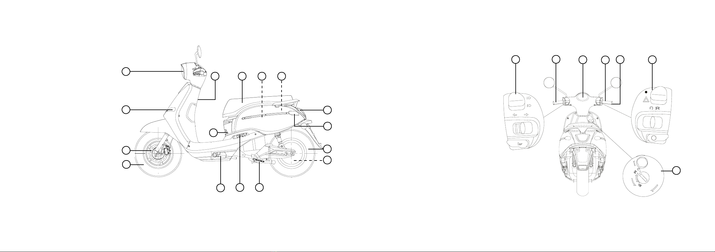
DESCRIPTION OF THE VEHICLE
SIDE VIEW
1. Front wheel
2. Front disc brake
3. Front turn signal light
4. Headlight
5. Helmet holder
6. Charging socket
7. Seat
8. Battery
9. Controller
10. Tail/brake light
11. Rear turn signal light
12. Rear wheel
13. Rear disc brake
14. Mainstand
15. Passenger footrest
16. Sidestand
2
3
4
1
10
11
13
12
16 1415
6
58
7 9
IG NI TI ON
SHU T
PUSH
OPEN
OPEN
R
56
4
123
7
CONTROLS AND INSTRUMENTS
1. Left handlebar switches
3. Dashboard unit
4. Front brake lever
5. Throttle grip
6. Right handlebar switches
7. Main switch

20 21
VIN (vehicle identification number) or FRAME
Number
Please write down the VIN (vehicle identification number) to
order replacement parts from your dealer or the vehicle should
be stolen.
The chassis number is stamped into the frame. To see this, take
the cover (1) from the inner lining in the footplate.
Caution: The vehicle identification number is used to identify
your motorcycle and may be used to register your vehicle with
the
licensing authority in your area.
1
INSTRUMENT AND CONTROL
FUNCTIONS
Main switch
The main switch controls the ignition and
lighting systems, and also used to lock the
steering. The various positions are descri-
bed as below.
On “ ”
All electrical circuits are supplied with
power, the engine can be started. The key
cannot be removed.
Off “ ”
All electrical systems are off . The key can
be removed.
Steering lock
The steering is locked, and all electrical
systems are off. The key can be removed.
Lock the steering
1. Turn the handlebar fully to the left.
2. Insert the key into the main switch.
3. Turn the key while you apply pressure to
it, counterclockwise in the position. If the
lock does not engage immediately, move
the handlebars back and forth slightly.
4. Remove the key.
Unlock the steering
1. Insert the key into the main switch.
2. Turn the key clockwise to the position.
If the lock does not engage immediate-
ly, move the handlebars back and forth
slightly.
Warning:
Never turn the key to or , while the
vehicle is moving, otherwise the electrical
systems will be switched off, which may re-
sult in loss of control or an accident. Make
sure that the vehicle is stopped before
turning the key.
Open the glove compartment
When in „OFF“ position, turn the key coun-
terclockwise without pushing it in to open
the glove compartment.
DASHBOARD UNIT
1. Turn signal indicator light or
2. High beam indicator lamp
3. Odometer
4. Speedometer
5. Battery capacity indicator
6. Gear indicator
7. Battery percentage indicator (charging)
IG NI TI ON
SHU T
PUSH
OPEN
OPEN
H
L
MPH
Km/h
%
MIL
Km
ODO
1 1
735
4 62

22 23
1. Turn signal indicator light /
This indicator light flashes when the turn
signal light is activated.
2. High beam indicator lamp
Lights up whenever high beam is switched
on.
3. Odometer
The dashboard unit is equipped with an
odometer. The odometer shows the total
distance traveled.
4. Speedometer
The dashboard unit is equipped with a
speedometer. The speedometer shows the
riding speed.
5. Battery capacity indicator
This indicator shows the remaining capa-
city of the battery. The needle moves from
„H“ towards „L“ (Empty) as the capacity
decreases.
6. Gear indicator
This indicator shows the current selected
gear. „P“ stands for the park gear,
„1“ limits the speed to 25 km/h and „2“
limits the speed to 45 km/h.
7. Battery percentage indicator (char-
ging)
Displays the current percentage of the
battery, when charging.
HANDLEBAR SWITCHES - LEFT
1
2
3
1. High / Low beam switch /
2. Turn signal switch
3. Horn switch
1. High / Low beam switch /
Set this switch to for the high beam
and to for the low beam.
2. Turn signal switch /
To signal a right-hand turn, push this
switch to . To signal a left-hand turn,
push this switch to . When released
the switch returns to the center position.
To cancel the turn signal lights, push the
switch in after it has returned to the center
position.
3. Horn switch
Press this switch to sound the horn.
HANDLEBAR SWITCHES - RIGHT
5
R
4
6
4. Warning light switch /
5. Safety switch
6. Electro start switch / Reverse switch
4. Warning light switch /
By changing the switch position you can
switch on or off the warning light.
5. Safety switch
If the safety switch is activated , the en-
gine can be started. if the switch is deacti-
vated , the engine can not be started
6. Electro start switch / Reverse switch
After turning on the main switch, push this
switch once to activate the engine. The
vehicle is ready to drive.
Caution: Before starting the vehicle
check the notes in the user manual.
If you hold this switch and turn the throttle
grip, the reverse will be activa- ted and the
vehicle will slowly start to roll backwards
BRAKE LEVER
The front brake lever is located on the
right handlebar grip. To apply the front
brake, pull this lever toward the hand- le-
bar grip.
The rear brake lever is located on the left
handlebar grip. To apply the rear brake,
pull this lever toward the handlebargrip.
SEAT
To open the seat
1. Place the vehicle on the centerstand.
2. Insert the key into the seat lock (1), and
then turn the key clockwise to “OPEN” the
seat.
Caution: Do not push inward when
turning the key.
3. Fold the seat up.
To close the seat
1. Fold the seat down, and then push it
down to lock it in place.
• When you close the seat by force or stri-
ke, parts can be damaged.
• Make sure that the seat is locked before
driving or when you park the vehicle.
HELMET HOOK
Caution: Do not exceed the load limit of 1
kg for the front Hook (1).
1
SIDE STAND
1
The side stand (1) is located on the left
24 25
side of the vehicle. Release the sidestand
by using your feet to step on the bracket
of side stand to up-right position to stand
the vehicle.
Caution:
• The side stand with auto-rebound
system. Make sure your vehicle have been
park well are stable enough to stand the
vehicle.
• Please avoid to use side stand to park the
vehicle on the slope, soft land or un-flat
ground.
MAIN STAND
2
The main stand (2) is located under the
vehicle. Release the main stand by using
your feet to step on the bracket of side
stand to up-right position to stand the
vehicle.
The main stand with auto-rebound
system. Make sure your vehicle have been
park well are stable enough to stand the
vehicle.
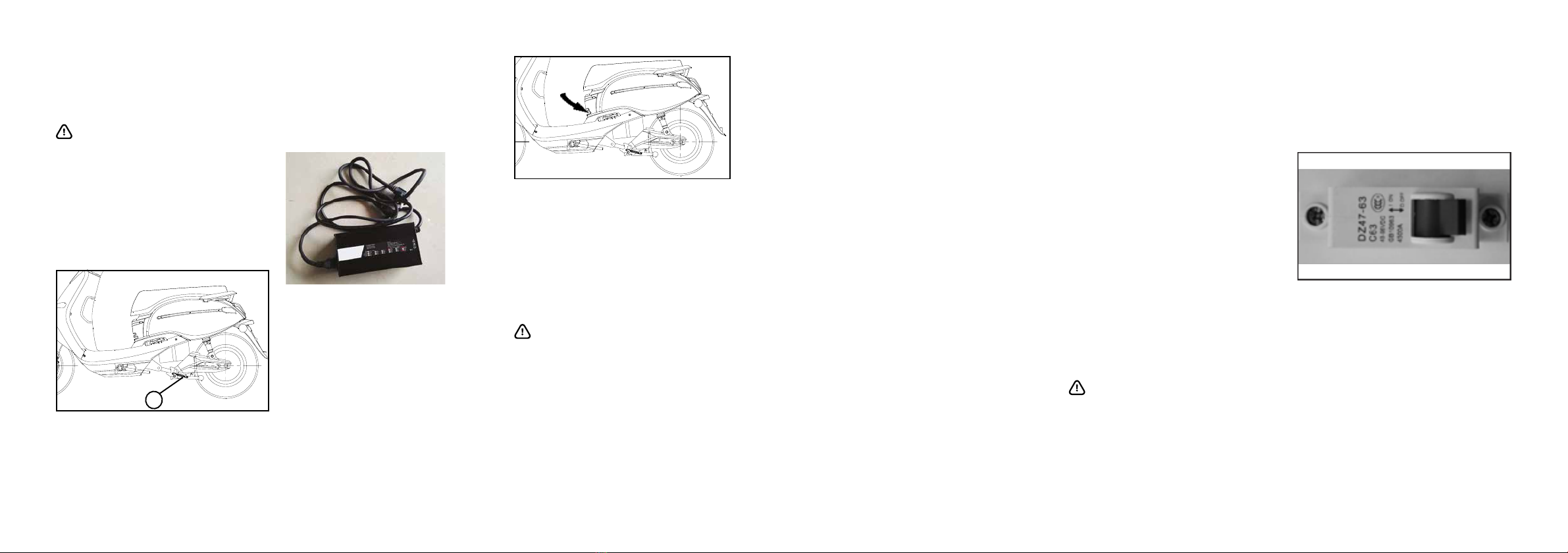
CHARGER AND CHARGING PORT
Attached to the vehicle is a charger (1). If
you reach the red area of the charge indi-
cator on the dashboard, charge the vehicle
immediately.
The charging port is located at the front,
under the seat.
CHARGE THE BATTERY
1. Turn the ignition off.
2. Plug the charger into the vehicle‘s char-
ging port.
3. Plug the power plug into an AC outlet.
4. When the battery is charged, the charger
LED turns green from RED.
Caution:
• Charge the battery at regular intervals to
avoid a deep discharge even if the vehicle
is not being operated.
• Charge the battery 3 to 5 hours, depen-
ding on the previous operating time of the
vehicle.
• Charge after each trip is recommended to
ensure the full availability of your vehicle
at all times.
• If you are not using the vehicle for an ex-
tended period of time, set the circuit break
switch to „OFF“.
• Charge the battery only in a dry and
clean environment.
• Do not charge if the charging port is wet.
• Do not cover the scooter and/ or charger
when charging.
• The life and performance of a battery de-
pends on its age, the care and how often it
was in use.
• The batteries have a very low selfdischar-
ge and a very low memory effect so they
can be part charged.
• Regular charging keeps the battery from
deep discharge. Please note that a deeply
discharged battery is irreparably dama-
ged and must be replaced, so the battery
should never be fully discharged.
• The best way to store the battery is at 7 -
15 ° C room temperature and dry environ-
ment, this reduces the self-discharge.
• Do not heat or expose the battery
to open fire.
• Never dispose of accumulators over
household waste.
• Never touch the battery contacts with
moisture.
• The best operating temperature is bet-
ween 5 ° C and 30 ° C.
• The max. Range in optimal conditions
is up to 50 km. The driving behavior and
various external factors have an influence
on the range.
IDEAL CONDITIONS
Flat terrain, constant speed - no full load,
no headwind, correct tire pressure, driver
weight <70 kg, no payload, approx. 20 ° C
ambient temperature.
BATTERY CONSERVATION
Lithium batteries have a freezing point of
approx. - 20 ° C to -25 ° C, depending on
the state of charge. As with conventional
batteries, a lithium battery loses up to
40% of its capacity starting at approx. 0
° C. At approx. 20 ° C and 100% charge, a
lithium battery loses approx. 30% of capa-
city per month (poor storage) At approx.
7 ° C and 70% charge, however, a lithium
battery loses only approx. 5% of capacity
per month (optimal Storage).
Caution: If a BMS (Battery Manage-
ment System) is installed in a Lithium
battery pack, the self-discharge is compa-
rable to a conventional battery in storage
condition (Caution: Overcharging). The
BMS system reduces the battery capacity
but is necessary and mandatory for cell
balancing. (uniform cell discharge).
CIRCUIT BREAK SWITCH
The circuit break switch is located in the
shaft under the seat. This circuit break
switch interrupts any power consumption
of your vehicle.
If you do not wish to operate the vehicle
for an extended period of time, it is advisa-
ble to interrupt the power supply with the
circuit break switch. The battery has to be
recharged in this time period. Information.
If there is a short circuit in the electrical
system, this switch automatically jumps
to „OFF“ to prevent further damage to the
vehicle.

26 27
PRE-OPERATION CHECKS
The condition of a vehicle is the owner’s
responsibility. The operator should check
the vehicle by simple but thorough inspec-
tion,to make sure of vehicle condition,
quick inspect some key and important
parts, to prevent the vehicle from serious
consquence/accident. Please carefully
check the following points before each
ride.
Caution: Pre-operation checks should
be made each time the vehicle is used.
Such an inspection can be accomplished
in a very short time; and the added safety
it assures is more than worth the time
involved.
Warning:If any item in the Pre-ope-
ration check list is not working properly
, have it inspected and repaired before
operating the vehicle. If failed to be correc-
ted by yourself, please turn to repair shop
immediately.
If failed to be corrected by yourself, please
turn to repair shop immediately.
CHECKPOINT TO VERIFY
Front brake • Check operation.
• If soft or spongy, have dealer bleed hydraulic system.
• Check brake pads for wear, replace if necessary.
• Check fluid level in reservoir, add recommended brake fluid to specified level if neces-
sary.
• Check hydraulic system for leakage."
Rear brake • Check operation.
• If soft or spongy, have dealer bleed hydraulic system.
• Check brake pads for wear, replace if necessary.
• Check fluid level in reservoir, add recommended brake fluid to specified level if neces-
sary.
• Check hydraulic system for leakage."
Throttle grip • Make sure that operation is smooth.
• If necessary, have dealer adjust cable free play and lubricate cable and grip housing."
Wheels and tires • Check for damage.
• Check tire condition and tread depth.
• Check air pressure."
Brake levers • Make sure that operation is smooth. Lubricate lever pivoting points if necessary.
Main stand • Make sure that operation is smooth. Lubricate pivot if necessary.
Chassis fasteners • Make sure that all nuts, bolts and screws are properly tightened. Tighten if necessary.
Instruments, lights, signals and switches • Check operation, correct if necessary
Battery • Check the charge level.
• Charge battery, or replace if defective."
PRE-OPERATION CHECK LIST
28 29
OPERATION AND IMPORTANT
RIDING POINTS
Warning
• Before riding the vehicle, please make
sure that you are fully fimiliar with all
operating controls & their functions before
riding. To consult a dealer shop if you not
thoroughly understand.
STARTING THE ENGINE
To start the engine you have to turn the
main switch to and press the starting
switch.
STARTING OFF
1. Sit astride the seat, and then adjust
the rear view mirrors.
2. Switch the turn signal on to the directi-
on you wish to turn.
3. Check for oncoming traffic.
4. Slowly open the throttle to accelerate.
5. Switch the turn signal off.
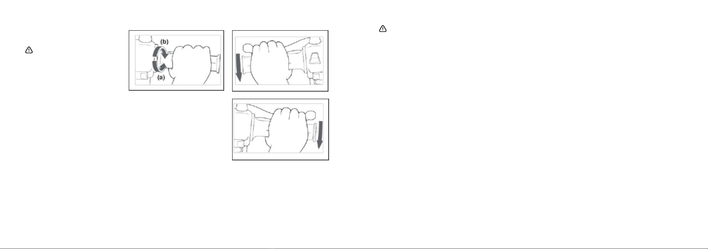
ACCELERATION / DECELERATION
The speed can be adjusted by opening
and closing the throttle. To increase the
speed, turn the throttle grip in direction
(a). To reduce the speed, turn the throttle
grip in direction (b).
BRAKING
1. Release the throttle.
2. Apply the front and rear brake at the
same time.
Rear
Front
Warning
• Avoid braking hard or suddenly, otherwi-
se the vehicle may skid.
• Railroad crossings, streetcar rails, iron
plates on road construction sites, and
manhole covers become extremely slippe-
ry when wet. Therefore, slow down when
approaching such areas and cross them
with caution.
• Keep in mind that braking on a
wet road is much more difficult.
• Ride slowly down a hill, as bra-
king downhill can be very difficult.
STOP THE ENGINE / PARKING
1. Reduce the throttle to 0 position.
2. Operate the brakes
3. Once the vehicle is stopped turn off the
ignition.
4. Lower the side /main stand with your
foot while holding the motorcycle upright.
Remove the key from the main switch.

30 31
WARNING
Maximum load*: 150kg
Do not over load your vehicle, since it will
increase pressure on the tire, braking,
steering than original design,
and may could cause damge or even lead
to accident.
Allocation of your cargo and weight of
your vehicle is very important for your own
safety and vehicle performance. Load your
cargo rmly on vehicle and put the heaviest
cargo to the center of vehicle, then distri-
bute the weight evenly from side to side. It
will keep you to have good steering after
load.
Tire inspection
1
2
3
1. Tire tread depth
2. Tire sidewall
3. Tire wear indicator
WARNING
The tires must be checked before each
ride. If a tire tread shows crosswise lines
(minimum tread depth), if the tire has a
nail or glass fragments in it, or if the side-
wall is cracked, have a dealer replace the
tire immediately.
Caution
The tread depth may vary depending on
country. Observe local regulations. The
values listed here are technical values and
may differ from the legal values of your
region.
Minimum tire tread depth:
Front and rear: > 1.6 mm
WARNING
• Drive with worn tire is illegal, reduces
stability and can lead to loss of control
over the vehicle.
• Let worn or damaged tires replaced
immediately by your dealer.
• Working tires and the dealer is respon-
sible.
Dimensions Tires / Rims
Front Rim: MT 2,75×12 Tire: 110/70-12
Rear Rim: 2,75×12 Tire: 110/70-12
Tyre type: Tubeless
RIMS
To maximize the performance, durability,
and safe operation of your motorcycle,
note the following points regarding the
specified wheels.
• The wheel rims should be checked for
cracks, bends or warpage before each ride.
If any damage is found, have a dealer re-
place the wheel. Do not attempt even the
smallest repair to the wheel. A deformed
or cracked
wheel must be replaced.
• The wheel should be balanced whenever
either the tire or wheel has been chan-
ged or replaced. An unbalanced wheel
can result in poor performance, adverse
handling characteristics, and a shortened
tire life.
• Ride at moderate speeds after changing
a tire since the tire surface must first be
“broken in” for it to develop its optimal
characteristics.
PERIODIC MAINTENANCE AND
MINOR REPAIR
Caution: Most of the Safety and condi-
tion of vehicle depend on how you do the
correct maintenance , periodic inspection,
adjustment and lubrication. The following
are contents that help the operator to do
such skills on the following pages.
WARNING
Maintenance, replacement, or repair of
the emission control devices and systems
may be performed by any repair shop or
individual that is certified and must follow
the local law regulations. If you are not
familiar with maintenance work, have a
dealer do it for you.
OWNER’S TOOL KIT
The owner’s tool kit is located under the
seat.
The service information included in this
manual and the tools provided in the
owner’s tool kit are intended to assist you
in the performance of preventive mainte-
nance and minor repairs. However, additi-
onal tools such as a torque wrench may be
necessary to perform certain maintenance
work correctly.
Caution: If you do not have the tools
or experience required for a particular job,
have a dealer perform it for you.
WARNING
Modifications not approved by maker
may cause loss of performance, excessive
emissions, and render the vehicle unsafe
for use. Consult a dealer before attemp-
ting any changes. Modifications without
authorization of the manufacturer cause
void the warranty.
BATTERY
The battery (1) is located under the
seat.
1
TIRES
To maximize the performance, durability,
and safe operation of your vehicle, note
the following points regarding the specifed
tires.
Tire air pressure
The tire air pressure should be checked
and, if necessary, adjusted before each
ride.
Tire air pressure:
Front: 2.2 bar - 2.3 bar
Rear: 2.2 bar - 2.3 bar
Total weight of rider, passenger, cargo and
accessories!
WARNING
The tire air pressure must be checked and
adjusted on cold tires (i.e., when the tem-
perature of the tires equals the ambient
temperature).
The tire air pressure must be adjusted in
accordance with the riding condition. If
you are not familiar to this, please have
dealer for help.

32 33
BRAKE FREE PLAY
There should be no free play at the brake
lever end. If there is free play, have a dea-
ler inspect the brake system.
WARNING
A soft or spongy feeling in the brake lever
can indicate the presence of air in the hy-
draulic system. If there is air in the hydrau-
lic system, have a dealer bleed the system
before operating the motorcycle. Air in the
hydraulic system will diminish the braking
performance, which may result in loss of
control and an accident.
BRAKE PADS
The brake pads must be checked for wear
at the intervals specified in the periodic
maintenance and lubrication chart.
Brake pads
Each brake pad is provided with wear
indicators, which allows you to check
the brake pad wear without having to
disassemble the brake. To check the brake
pad wear, check the position of the wear
indicators while applying the brake.
If a brake pad has worn to the point that a
wear indicator almost touches the brake
disc, have a dealer replace the brake pads
as a set.
BRAKE FLUID
Insufficient brake fluid may allow air to
enter the brake system, possibly causing it
to become ineffective. Before riding, check
that the brake fluid is above the minimum
level mark and refill it if necessary.
DOT 4 break fluid
(Only use brake fluid out from an unope-
ned container)
• Low position brake fluid level may indi-
cate worn brake pads and/or brake system
leakage.
• If the brake fluid level is low, be sure
to check the brake pads for wear and the
brake system for leakage.
• When checking the fluid level, make sure
that the top of the master cylinder is level
by turning the handlebars.
• Use only the recommended qua lity
brake fluid, otherwise the rubber seals
may deteriorate, causing leakage and poor
braking performance.
• Refill with the same type of brake fluid.
Mixing fluids may result in a harmful che-
mical reaction and lead to poor braking
performance.
• Be careful that water does not enter the
master cylinder when refilling. Water will
significantly lower the boiling point of the
fluid and may result in vapor lock.
• Brake fluid may deteriorate painted sur-
faces or plastic parts. Always
clean up spilled fluid immediately.
• As the brake pads wear, it is normal for
the brake fluid level to gradually go down.
However, if the brake fluid level goes down
suddenly, have a dealer check.
Changing the brake fluid
WARNING
Have a dealer change the brake fluid at
the intervals specified in the NOTE after
the periodic maintenance and lubrication
chart.
LUBRICATING THE BRAKE LEVERS
The pivoting points of the front and rear
brake levers must be lubricated at the
intervals specified in the periodic mainte-
nance and lubrication chart.
Front brake lever
Rear brake lever
SIDE STAND / MAIN STAND
2
1
Caution:
The operation of the side stand (1) and
main stand (2) should be checked before
each ride, and the pivots and metal-to-me-
tal contact surfaces should be lubricated if
necessary
WARNING
If the main stand does not move up and
down smoothly, have a dealer check or
repair it.
FRONT FORK
The condition and operation of the front
fork must be checked as follows at the
intervals specified in the periodic mainte-
nance and lubrication chart.
WARNING
Securely support the motorcycle so that
there is no danger of it falling over.
1. Place the vehicle flat and upright
from.
2. Check the inner tubes for scratches,
damage and oil leakage.
3. Apply the front brake and push the
handlebars several times down hard to
verify the suspension of the fork
WARNING
• When damage to the fork, please contact
your dealer.
• If you treat the telescopic fork with cle-
aning agents, make sure that they get no
contact with the tires or the brakes. This
can lead to dangerous accidents.
STEERING
WARNING
Worn or loose steering bearings may cause
danger. Therefore, the operation of the
steering must be checked as follows at the
intervals specified in the periodic mainte-
nance and lubrication chart.

34 35
1. Place the vehicle on the center stand/
suitable motorcycle stand to raise the
front wheel off the ground.
2. Hold the lower ends of the front fork
legs and try to move them forward and
backward.
3. If any free play can be felt, have a dealer
check or repair the steering.
WHEEL BEARINGS
The front and rear wheel bearings must
be checked at the intervals specified in
the periodic maintenance and lubrication
chart.
If there is play in the wheel hub or if the
wheel does not turn smoothly, have a
dealer check the wheel bearings.
BATTERY
This model is equipped with a sealedtype
(MF) battery, which does not require any
maintenance. There is no need to check
the electrolyte or to add distilled water.
WARNING
• Do not remove the battery vent seal, this
can be dangerous, the battery permanent-
ly damaged.
• Battery acid is poisonous and dangerous,
it contains sulfu ric acid and leads to
dangerous burns.
• Avoid skin, eye and clothing contac.Pro-
tect your eyes always when working near
the battery.
• Upon contact with the battery aicd, make
immediate FIRST AID.
• If skin or eye contact with battery acid,
rinse the affected areas with plenty of
water.
• When accidentally swallowed battery
acid drink large amounts of water.
• In both cases, as soon as possible, see a
doctor.
• Batteries develop explosive hydrogen
gas. Keep open flames, smoking materi-
als away from the battery and make sure
there is adequate ventilation when you
charge a battery indoors.
• KEEP THIS AND ALL BATTERIES OUT OF
THE REACH OF CHILDREN.
Charge the battery
Have a dealer charge the battery as soon
as possible if it seems to have di-
scharged. Keep in mind that the battery
tends to discharge more quickly if the
vehicle is equipped with optional electri-
cal accessories.
Store the battery
• If the vehicle will not be used for more
than one month, remove the battery, fully
charge it, and then place it in a cool, dry
place.
• If the battery will be stored for more
than two months, check it at least once a
month and fully charge it if necessary.
• Fully charge the battery before installa-
tion.
• After installation, make sure that the
battery leads are properly connected to
the battery terminals.
WARNING
Please contact your dealer if you are not
familiar with handling the battery.
Always keep the battery charged. Storing a
discharged battery can cause permanent
battery damage.
FUSE
The fuse holder (1) is located behind
seat lock.
Replacing the fuse
1. Turn the key to and turn off all electri-
cal circuits.
2. Remove the blown fuse, and then install
a new fuse of the specified amperage.
Specified fuse: 15 A
3. Turn the key to and turn on the
electrical circuits to check if the devices
operate.
4. If the fuse immediately blows again,
have a dealer check the electrical system.
WARNING
Do not use a fuse of a higher amperage ra-
ting than recommended to avoid causing
extensive damage to the electrical system
and possibly a fire.
LIGHTING
This model is equipped with halogen bulb
headlight. If the halogen bulb burns out,
have a dealer replace it and, if necessary,
adjust the headlight beam.
All other lights on this vehicle are equip-
ped with LED. If a lamp is damaged, con-
tact your dealer for replacement.

36 37
TROUBLESHOOTING
Although the vehicles receive a thorough
inspection before shipment from the fac-
tory, trouble may occur during operation.
However, should your vehicle require any
repair, take it to a dealer, whose skilled
technicians have the necessary tools,
experience, and knowhow to service the
vehicle properly.
Use only genuine replacement parts. Imi-
tation parts may look like genuine parts,
but they are often inferior have a shorter
service life and can lead to expensive
repair bills.
CLEAN AND STORAGE
CLEAN THE VEHICLE
Clean of the vehicle in proper and suitable
way will make it attractive, extend it’s lfe
and optimize the performance.
Before cleaning
Close every caps, covers and electrical
connectors to prevent them of getting wet
while cleaning.
• Do not use acid-based cleaners. If such
funds used for stubborn stains, so use this
only occasionally, dry it immediately after
and then apply a corrosion protection
spray.
• Always follow the manufacturer‘s instruc-
tions on care and cleaning agents.
• Use best only water and mild detergent
or special cleaner from the dealer to the
sensitive components of the vehicle to
prevent damage. Dry the plastic parts then
wipe with a soft, dry cloth or sponge.
• Protect particularly plastic parts, paint,
headlight glass from harsh chemicals such
as fuel, rust remover, brake cleaner or
similar. The use of such agents may result
in malfunction, damage and affect the
security itself.
• Do not use a high pressure washer or
steam cleaner, causing water in storage
can penetrate electrical components such
as connectors or switches, lighting, brake
shoes and brake linings or damage, seals,
paint and other surfaces.
Cleaning after normal use
Remove dirt with warm water, a mild de-
tergent, and a soft, clean sponge, and then
rinse thoroughly with clean water. Use a
brush for hard-to-reach areas.
Cleaning after riding in the rain, near the
sea or on salt-sprayed roads
Since sea salt or salt sprayed on the roads
during winter are extremely corrosive in
combination with water, carry out the
following steps after each ride.
• Clean the vehicle with water and a mild
detergent.
• Do not use hot water, which increases the
corrosive effect of the salt.
• Apply a corrosion protection spray on all
metal, including chrome- and nickel-pla-
ted, surfaces to prevent corrosion.
After cleaning
• Dry the vehicle.
• To prevent rust, we recommend appro-
priate care to use according to manufactu-
rer‘s instructions.
• Wax all painted surfaces.
WARNING
• Make sure that there is no oil or wax on
the brakes or tires.
• If necessary, clean the brake discs and
brake linings with a regular brake disc cle-
aner and wash the tires with warm water
and a mild detergent.
• Before operating the vehicle, test the
braking performance and tires.
STORAGE
Short-term (for a few days)
• Always store your vehicle in a cool, dry
place and, if necessary, protect it against
dust with a vehicle cover.
WARNING
Please store the vehicle in a well air flow
room with dry air if possible. A place with
wet humidity will cause rust.
Long-term (for weeks)
• Clean the vehicle.
• Check and correct tire pressure and lift
the vehicle off the ground, so that neither
of the two wheels is on the ground. If this
is not possible, turn the wheels every
month a little further, so they do not
constantly the same place standing (Stand
damage).
• If you are not using the vehicle for an
extended period of time, set the circuit
breaker to „OFF“. During this time, the
battery has to be charged according to the
manual.

38 39
SPECIFICATIONS Revival
BATTERY LITHIUM
BATTERY VOLUMN 60V32Ah
CHARGE TIME(HOUR) 5,6
BATTERY CHARGE NUMBER OF TIMES" 1000
INPUT VOLTAGE 110/220V
MOTOR 3000W
MAX SPEED(KM/HOUR) 25,45
MILEAGE(KILOMETER) 75
CLIMBING ABILITY 15%
NET WEIGHT (KG) 88
FRONT TIRE 110-70/12
REAR TIRE 110-70/12
BRAKE DISC/DISC
FROTN/REAR ABSORBER FRONT HYDRAULIC REAR SPRING
SIZE 1875*700*1140
WHEELBASE 1365
GROUND DISTANCE(MM) 140
SPECIFICATIONS econeco S1
BATTERY LITHIUM
BATTERY VOLUMN 60V20Ah
CHARGE TIME(HOUR) 8
BATTERY CHARGE NUMBER OF TIMES" 300
INPUT VOLTAGE 110V/220V
MOTOR 2000W
MAX SPEED(KM/HOUR) 25 - 45
MILEAGE(KILOMETER) 60
CLIMBING ABILITY 12%
NET WEIGHT (KG) 75
FRONT TIRE 3.00-10
REAR TIRE 3.00-10
BRAKE DISC/DRUM
FROTN/REAR ABSORBER FRONT HYDRAULIC REAR SPRING
SIZE 1670*700*1120
WHEELBASE 1200
GROUND DISTANCE(MM) 110
This manual suits for next models
1
Table of contents


