Economix Zlin Z-526 AFS User manual

Zlin Z-526 AFS
Specification:
Length :1875 mm(73.8")
Wing Span :2085 mm(82")
Wing Area :76.2sq.dm
8.19sq.ft
Wing Loading :70.9g/sq.dm
23.2oz/sq.ft
Flying Weight :5.4kg(11.9lbs)
Radio :6ch & 8servos
Engine: :26cc-36cc
SAFETY PRECAUTIONS
INSTRUCTION MANUAL
First-time builders should seek advice from people having building
experience.If misused or abused,it can cause serious bodily injury
and damage to property.
Fly only in open areas and preferably at a dedicated R/C flying site.
We suggest having a qualified instructor carefully inspect your
airplane before its first flight.Please carefully read and follow all
instructions included with this airplane,your radio control system
and any other components purchased separately.
(The people under 18 years old is forbidden from flying this model)
This R/C airplane is not a toy!

: 4-cycle .120
15
"
X7
6
(with 8 servos),
6
6
6 channel radio for aiplane is highly recommended for this model.
Warning
Remove the covering with proper
pressure to cut through only the covering itself.Otherwise,
cutting down into the balsa structure may weaken the
model part and cause accident.
The pre-covered film on ARF kits may wrinkle due to
variations of temperature.Smooth out as explained right.
2.5 in Spinner
Pre-cover the covering with clean cloth!
Start at low setting. Increase the setting if
necessary.If it is too high,you may damage
the film.
Iow setting
with cover(cloth)
45mm
45mm
AILERON
Adjustment of the aileron and flap,be sure they can work
perfectly.
42mm
42mm
Top view
RUDDER
Side View
Adjustment of the rudder, be sure it can work perfectly.
137mm
137mm
Centre of the Gravity.
Top view
Position for
right diagram.
ELEVATOR
40mm
40mm
Adjustment of the elevator,be sure it can work perfectly.
TP Screw (2.3x12mm)
Collar (5mm)
Wooden supporter
Install the wheel to the fixed landing gear.
Epoxy the fixed landing gear to the main wing.
8
TP Screw (2.3x12mm)
Landing gear straps 4
Collar 5mm 2
AILERON AILERON
51
13
48
52
49
50 53
Washer (3x6mm) 2
2
Accessory list for the coming installation steps.
Accessory list for the coming installation steps.
Mount the receiver and the battery to appropriate position
in the fuselage.
Screw (3x16mm)
4
TP Screw (2.3x12mm)
Fix the fuselage top cover to the fuselage with screws as
illustration.
Washer (3x6mm) 2
2
Screw (3x16mm)
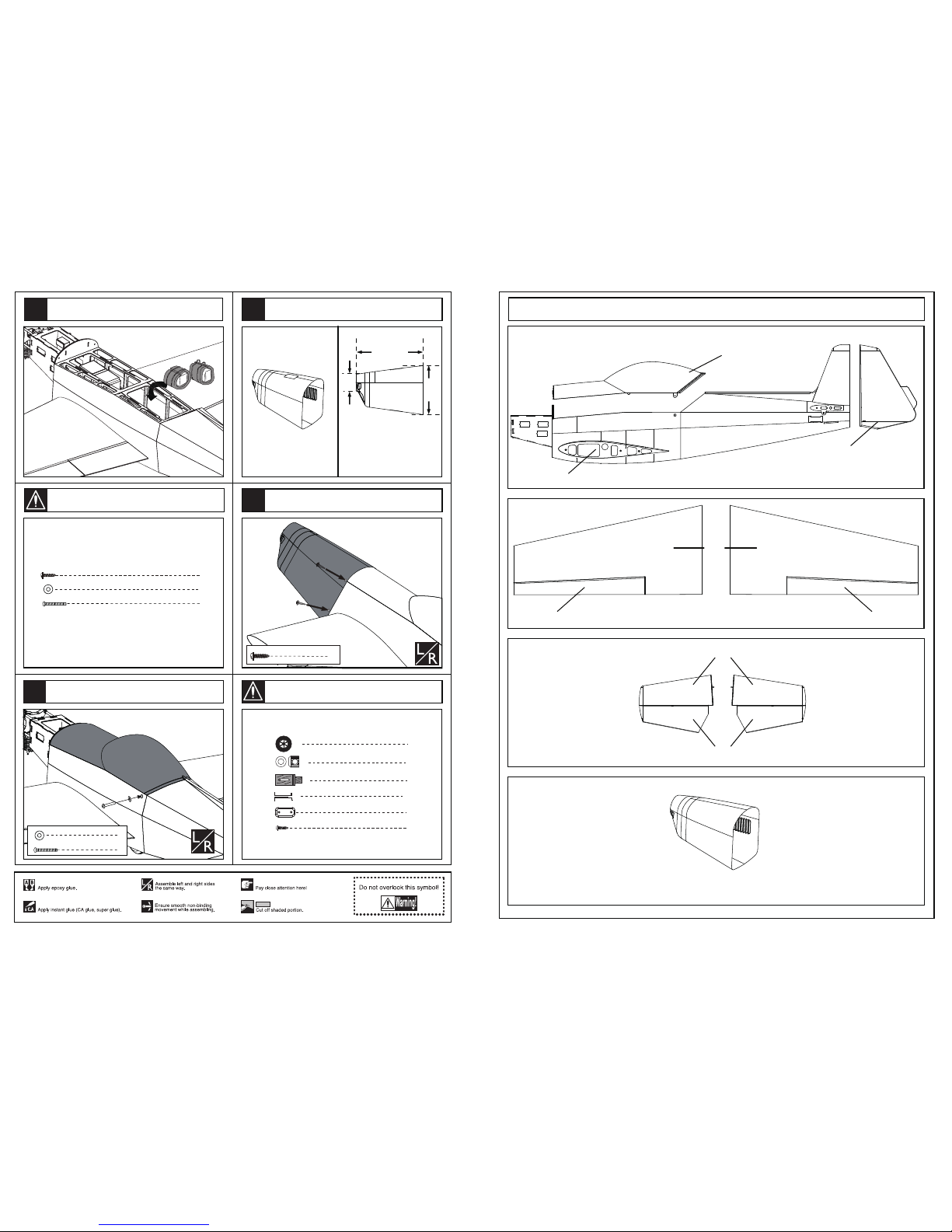
The specification of the cowling.
345mm
244mm
80mm
Drill holes to appropriate position in the cowling and assemble
the cowling to the fuselage with TP screws as illustration.
4
TP Screw (2.3x12mm)
2
2
Collar (5mm)
Wheel (100mm)
Wooden supporter 2
Landing gear straps
4
2
Landing gear (5mm)
8
TP Screw (2.3x12mm)
45
46
47
12
44
Fuselage
Rudder
Top cover
wing
Aileron Aileron
Stabilizer
Elevaror
Cowling
Zlin Z-526 AFS packing list
1

31
TP Screw (2.3x12mm)
Screw (4x20mm)
Screw (4x35mm)
Screw (2x10mm)
Screw (3x16mm)
2
2
2
Collar (2mm)
5
Collar (3mm)
2
Collar (5mm)
2
6
6
6
Nut(2mm )
Nut(3mm )
6
Washer(2x6mm)
Washer(3x6mm)
Washer(4x8mm)
Washer(6x12mm)
6
22
1
1
12
2
1
1
4
4
Screw (6x35mm)
2
2
4
Blind Nut(4mm)
Wheel(100mm)
Wheel(45mm)
Rod (2.5x300mm)
2
Rod (2x300mm)
Control horn
4
Control horn
Linkage Stopper
Landing gear straps
Landing gear
Landing gear
Wooden supporter
Clevis(3mm)
6
Clevis(2mm)
Plastic tube (2x400mm)
Fuel tank (550cc)
Rod (2x200mm)
2
4
2
1
2
Cable tie
2
Steelwire (0.5x3000mm)
4
Copper joiner
1
Aluminium plate
4
Aluminium tube
1
1
Wing joiner(27x700mm)
Stabilizer joiner(12x297mm)
Zlin Z-526 AFS packing list
Package1 Package4
Packaeg5
Package2
Package3
2
Linkage Stopper
Washer (2mm)
Washer (2mm)
Nut (2mm)
Set screw (3x4mm)
Washer (
2mm
)
Set screw (3x4mm)
1
1
1
1
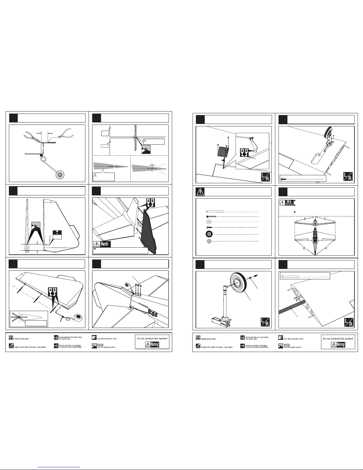
The sketch map when the engine install completion.
Install the servo of the throttle.
Assemble the servo of the throttle in the fuselage.
Fuel supply line
Fuel spray line
Air pressure line
Assembly of the fuel tank.
Fix the fuel tank to appropriate position in the fuselage
with cable tie.
cable tie
cable tie
cable tie 2
Set Screw (3x4mm)
Set Screw (2mm)
Rod (2x200mm)
Set Screw (2mm)
Washer (2mm)
Linkage Stopper
1
1
1
1
1
4
4
Washer (4x8mm)
4
Rod (2x200mm)
Blind Nut (5mm)
Screw (4x25mm)
Set Screw (3x4mm)
Assemble the throttle linkage.
39
38
43
41
42
11
40

5.2mm
Blind Nut
4
Blind Nut (4mm)
1
Linkage Stopper
12
4
Washer(4x8mm)
Screw (4x45mm)
2
4
Screw (4x20mm)
4
Plastic tube (2x400mm)
Fuel tank (550cc) 1
1
Cable tie 2
Rod (2x200mm)
Blind Nut (4mm)
The front view once the engine install completion.
The side view once the engine install completion.
162mm
Drill four holes at the diameters as shown for engine
mount.
Install the engine mount tubes to the fuselage,lock them
from inside of the fuselage.
4
Washer(4x8mm)
4
Screw (4x45mm)
Washer(4x8mm)
Screw (4x45mm)
Assemble the engine to the fuselage via the engine
mount tubes and screws.
Screw (4x20mm)
Washer(4x8mm)
4
Washer(4x8mm)
4
Screw (4x20mm)
33
34 37
35
10
36
Accessory list for the coming installation steps.
2
Lock Nut(4mm )
TP Screw (3x20mm) 8
2
Wheel(100mm)
Retract
landing gear
Zlin Z-526 AFS packing list
Package6 Package9
Packaeg9
Package7
Optional parts,should be purchased separately.
3

Securely glue together. If coming off during flights, you 'll
lose control of your airplane which leads to accidents!
8
2
2
Rod (2.5x300mm)
TP Screw (2.3x12mm)
Servo tray(70x58x2mm)
Pivot&round hinge(4.5X67mm)
8
Install the aileron servo to the servo mount as illustration
below.
Install the control horn and connect the linkage.
Make sure hinges are
mounted in the same line.
1mm
Trailing
edge
Cut away the rubber tube when
the epoxy glue dried.
Make sure they are in
the right position while
installing.
Aileron
Collar (2.5mm)
2
2
2
2
2
2
Screw (3x16mm)
Nut (3mm )
Clevis
Aluminum Washer (3x6mm )
Nut
Clevis
Washer 3x6mm
Screw 3x16mm
Collar
Control horn
8
pivot & round hinges(4.5x67mm)
Apply instant type AB glue to appropriate position in the
trailing edge and assemble the ailerons to them.
Apply instant type AB glue to appropriate position of the aileron and
pivot & round hinges. Insert the pivot & round hinges to the ailerons.
Keep about 1mm width space between the aileron and
the trailing edge.
Accessory list for the coming installation steps.
1
2
3
4
5
4
2
2
Clevis
Copper joiner
2
2
Screw (2x10mm)
Nut (2mm )
2
Washer(2x6mm)
Steel wire
Copper joiner
Lock Nut (2mm )
Screw (2x10mm)
Clevis
Washer(2x5mm)
Install the servo of the rudder.
The sketch map of how the steel wires works for the
rudder.
Epoxy the control horns to the slots in the rudder.
Nut 2mm
Washer(2x6mm)
Screw (2x16mm)
Lock the linkage to the control horn with screws and nuts
as below.
Assemble the servo of the rudder in the fuselage and
connect the servo and the rudder via steel wires.
Make sure to glue securely.
If not properly glued, a failure in flight may occur.
Temporarily fasten down the main wing and
check its correct position.
Securely glue together.If coming off during flights,
you'll lose control of your airplane which leads
to accidents!
The sketch map should be when the rudder and stabilizer
install completion.
A = A’
B = B’
AA’
BB’
Steel wire
Copper joiner
Aluminum tube
Clevis
28
29
30
27
31
32
9
1mm
Trailing
edge
Cut away the rubber tube when
the epoxy glue dried.
Make sure they are in
the right position while
installing.
Keep some space about 1mm width between the rudder
and tail edge.
Epoxy the pivot & round hinges to the rudder,drill holes to appropriate
position in the rudder and assemble the tail landing gear to it as shown.
According to the illustration below bend the tail landing
gear wire and cut off the surplus part.
Epoxy the rudder to the vertical fin..
Assemble the tail landing gear to tail fuselage as below.
Rudder
Make sure hinges are
mounted in the same line.
45mm
25mm
Securely glue together. If coming off during flights, you 'll
lose control of your airplane which leads to accidents!
TP Screw (2.3x12mm)
40mm
25mm
Trim a slot and drill a hole in the rudder for helping
assemble the tail landing to it.
3mm
22
21
8
24
23 26
25
The standard sketch map when the kit install completion.
Assemble the wheel to the retracts.
Assemble the retract.
1
wing joiner (25x700mm)
2
Washer (6x12mm)
2
Screw (6x35mm)
Make sure to glue securely.
If not properly glued, a failure in flight may occur.
Temporarily fasten down the main wing and
check its correct position.
Securely glue together.If coming off during flights,
you'll lose control of your airplane which leads
to accidents!
A=A'
B=B'
8
TP Screw (3x20mm)
Lock Nut(4mm )
Lock Nut(4mm )
2
2
Wheel(100mm)
Wheel(100mm)
8
TP Screw (3x20mm)
Insert the main wing joiner to one side of the lower wing.
Main wing joiner (16x499mm)
1
Main wing joiner (25x700mm)
Apply instant type AB glue to the control horn and the slots in
the aileron, insert the control horn to the slots as illustration.
6
7
8
9
10
5
Accessory list for the coming installation steps.

Make sure hinges are
mounted in the same line.
Apply instant type AB glue to appropriate position of the elevator and
pivot & round hinges. Insert the pivot & round hinges to the elevator.
1mm
Trailing
edge
Cut away the rubber tube when
the epoxy glue dried.
Make sure they are in
the right position while
installing.
Elevator
Accessory list for the coming installation steps.
2
2
2
Rod (2x300mm)
Pivot&round hinge(4.5X67mm)
6
Collar (2mm)
2
2
Nut (2mm )
1
Stabilizer joiner (12x297mm)
Washer(3x6mm)
2
Washer(2x6mm)
Screw (3x16mm) 2
Screw (2x10mm) 2
2
Clevis
8
Control horn
Fix the wing to fuselage with screws throught the holes
applied in the wings and fuselage.
Assemble the wing to the fuselage and insert the other side
main wing to the fuselage via main wing joiner as illustration.
Keep about 1mm width space between the elevators
and the stabilizers.
Assemble the elevators to the stabilizers via pivot & round hinges.
Securely glue together. If coming off during flights, you 'll
lose control of your airplane which leads to accidents!
Washer
Screw
2
Washer (6x12mm)
2
Screw (6x35mm)
TP Screw (2.3x12mm)
6
Pivot & round hinges(4.5x67mm)
15
11
14
13
6
12
Screw
Washer
2
Washer(3x6mm)
Screw (3x16mm) 2
Fix the stabilizers to the tail fuselage via screws.
4
Washer(2x6mm)
Screw (2x10mm) 4
Collar (3mm)
3
1
1
Tail landing gear 3mm
Tail wheel (45mm)
Aluminium plate
Accessory list for the coming installation steps.
Install the tail landing gear.
4
3
Clevis
4
Copper joiner
4
Aluminum tube
2
2
1
Steel wire (0.5x3000mm)
Collar
Collar
Collar
aluminium plate
TP Screw (2.3x12mm)
Control horn
Pivot&round hinge(4.5X67mm)
3
4
Nut (2mm )
Assemble the stabilizer to the fuselage through the tail joint.
Connect the control horn and the clevis via the linkage.
Nut
Washer 2x6mm
Screw 2x10mm
Collar
TP Screw (2.3x12mm)
Epoxy the control horn to the slots in the elevator,assemble the
elevator servo to the fuselage as illustration.
17
16
18
19
7
20
Table of contents
Popular Toy manuals by other brands

Synergy
Synergy e6 instruction manual

VTech Baby
VTech Baby Push & Play Elephant Parents' guide

Fisher-Price
Fisher-Price Baby GymTastics J0327 manual

Seagull Models
Seagull Models PERCIVAL MEW GULL Assembly manual

Hasbro
Hasbro Baby Alive Better Now Baby manual
 Ausf.E/F exterior quick start guide")
Eduard
Eduard Pz.38(t) Ausf.E/F exterior quick start guide

Hachette
Hachette AGORA MITSUBISHI A6M ZERO FIGHTER Build instructions

Extreme Flight
Extreme Flight F3A instruction manual

MTHTrains
MTHTrains RailKing C628 Diesel Engine Operator's manual

Faller
Faller 2 BUS STOP SHELTERS manual

Hasbro
Hasbro BABY ALIVE E6937 manual

Eduard
Eduard P-61A/B engine quick start guide


