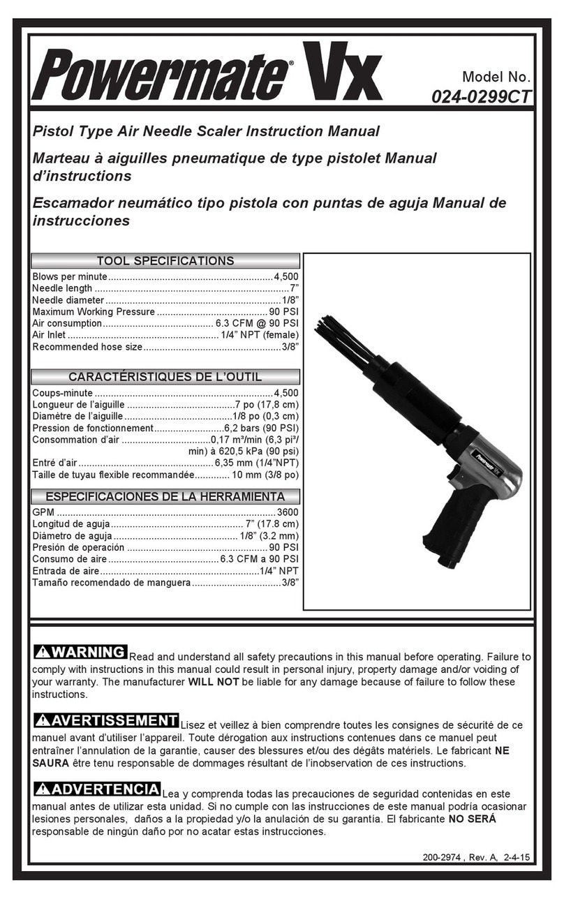
Ecotop Scale Series User manual

ATTENTION ! CAUTION !
Distribué par / Distributed by:
TOPMODEL S.A.S.
Le jardin d’entreprises de SOLOGNE - F-41300 SELLES SAINT DENIS
www.topmodel.fr
©TOPMODEL 2 014
Ce modèle à construire n’est pas un jouet, il
ne convient pas aux enfants de moins de
14 ans.
Une mauvaise utilisation de ce matériel peut
provoquer des dommages matériels
ou corporels. Vous êtes pleinement
responsable
lorsque vous utilisez votre modèle.
Volez à une distance de sécurité des zones
habitées.
Soyez sûr que personne n’émet sur la même
fréquence que vous.
This model construction kit is not a toy and is
not suitable for children under the age of 14.
Incorrect use of this material could cause
material damage ou personal injury.
You are fully responsible for your actions
when you use this model.
Fly at a safe distance from occupied zones.
Be sure that no one else is using the same
frequency as you.
Caractéristiques techniques / Technical data :
Echelle : 1:3
Envergure / wingspan : 5,00 m
Longueur / length : 2,29 m
Poids / TO weight : 9,0/9,5 kg (Avec motorisation / With power set)
Surface / wing area : 160 dm
2
Prol / airfoil : GOE 533 mod.
Equipements recommandés / Related items :
Moteur / motor : XPower XC5030/14 LS
Contrôleur / ESC : XPower XREG80 ou XREG100 HV Opto
Accu / Battery pack : LiPo Hot Lips 6S (22,2 V) 5000 mAh
Hélice / Propeller : Aeronaut CAM-CARBON 15 x 8”
Porte pales/prop hub : XPower 099H200807 (Modèle spécial en Z)
Radio / RC set : Récepteur/receiver : JETI DUPLEX R8
Ailerons : 2 servos TOPMODEL DS9010T
Profondeur/elevator : 2 servos TOPMODEL DS9010T
Direction/rudder: 1 servo TOPMODEL DS9010T
AF/SB : AF ELECTRIQUE/ELECTRIC SPOILER 300 mm (2 jeux/2 sets)
Accus de réception/Rx Battery : 2 x Lipo 2S 2200 mAh
Régul. de tension/Linear regulator : Jeti Max BEC 2
Planeur semi-maquette
Semi-scale sailplane
Order N° 066GKA8B33
Schleicher Ka-8b
Echelle
1:3
Scale
Scale series
Note: La gurine du pilote n'est pas fournie dans le kit. Pilot doll not included.
V. 1.02
ARF
Pour modélistes
experts
For experts
XP

Notice Ecotop - Page 2 - Ka-8b 1:3 - V.1.02
MERCI d’avoir choisi notre semi-maquette du planeur Ka-8b!
Nous avons fait un grand effort en dessinant et construisant ce planeur pour qu’il soit le meilleur modèle que vous ayez jamais
construit et fait voler. Nous vous fournissons un kit avec la plus haute qualité et les meilleures performances possibles. Nous vous
souhaitons un grand succès en assemblant et en faisant évoluer votre nouveau Ka-8b.
Vous avez déjà été nombreux à apprécier les versions à l'échelle 1:5 et 1:4 du Ka-8b, c'est-à-dire en 3 mètres et 3,75 mètres
d'envergure. Nous avons donc décidé de vous proposer ce même planeur à l'échelle 1:3, ce qui le porte à 5 m d'envergure. Il
devient ainsi une très grande plume ! Toutes les qualités de ses "petits frères" se retrouvent bien évidemment, et sont même encore
améliorées, car plus le modèle est grand, meilleur est son rendement. Il peut bien évidemment recevoir notre système exclusif de
motorisation à hélice rapidement démontable, qui ne dégrade pas le nez du modèle par un cône aussi peu esthétique que maquette.
Avec cette motorisation, vous pouvez vous passer de remorqueur, et lancer le planeur à la main seul, sans crainte.
Les points forts du Ka-8b
●Toute la cellule est réalisée en structure bois, balsa et contre-plaqué, et elle est d'une remarquable légèreté, en restant robuste.
●L'entoilage en Oracover est facile à entretenir.
●La motorisation puissante permet de voler en plaine sans l'aide d'un remorqueur et constitue une sécurité en vol de pente. Taux de
montée moyen mesuré à 5 m/s avec la motorisation recommandée. Vous montez à 200 mètres en 40 secondes.
●Les 4 aérofreins électriques facilitent les atterrissages sur des pistes courtes et ne provoquent pas de couple en tangage.
●Et bien sûr… le modèle est livré monté et entoilé, il ne vous reste plus que l’assemblage nal, le montage de la radio et de la
motorisation à réaliser.
Vous disposez avec le Ka-8b d'un planeur utilisable en plaine comme en pente, aux performances surprenantes, qui est une semi-
maquette au comportement particulièrement réaliste, mais qui sait rester accessible à tout pilote maîtrisant la conjugaison ailerons-
dérive.
Informations additionnelles:
●Le moteur optionnel est doté d'un arbre long, qui reçoit une hélice démontable en moins d'une minute, ce qui permet de passer d'une
conguration planeur électrique à une conguration planeur pur à loisir.
●La gigantesque dérive permet de piloter dans le style des vieilles toiles.
●L'accu 6S 5 000 mAh assure des vols de très longue durée, sans recourir à un remorqueur.
●Le prol GOE 533 très porteur, associé à une charge alaire très faible, assure une vitesse de vol réaliste.
IMPORTANT:
Merci de bien vouloir lire et étudier cette notice de montage avant de commencer l’assemblage. Faire l’inventaire des pièces à l’aide
de la nomenclature, pour contrôler qu’il n’y a pas d’élément manquant ou d’imperfection.
Merci de contacter immédiatement TOPMODEL si vous constatez une pièce manquante ou une pièce endommagée.
GARANTIE:
Il est important de notier à TOPMODEL tous dommages ou problèmes avec ce modèle dans les 7 jours suivant la réception du kit
pour bénécier de la garantie. En cas de retour du modèle, le client est responsable du transport et le port retour est à sa charge. En
cas de défaut, la pièce sera échangée ou remplacée une fois que celle-ci sera réceptionnée par TOPMODEL pour expertise (transport
à la charge du propriétaire). En cas de problème, n’hésitez pas à contacter TOPMODEL.
TOPMODEL ne peut pas contrôler la dextérité du modéliste et ne peut pas inuencer le constructeur durant l’assemblage ou l’utilisation
de ce modèle radiocommandé. Aussi, nous ne pouvons, en aucun cas, être tenus responsables des dégâts matériels, accidents
corporels ou décès pouvant être causés par ce modèle réduit.
L’acheteur/utilisateur accepte toutes les responsabilités en cas de problèmes
structurels ou mécaniques.
Pour assembler ce kit, vous aurez besoin des produits énumérés ci-dessous :
●COLLES: Cyano mi-uide, époxy 30 minutes et 5 minutes.
●OUTILS: Couteau de modéliste, tournevis cruciforme (petit et moyen), pince à bec n, pince coupante, ciseaux, ruban adhésif, ruban
adhésif de masquage, ruban adhésif double-faces, perceuse (foret tous diamètres), papier de verre, règle, feutre, alcool, fer à souder, chiffon, etc.
POUR ASSEMBLER CE KIT
RAPPEL
Nous prenons grand soin à fournir la meilleure qualité possible.
Toutefois, nous vous rappelons que ce ne sont pas des modèles prêts à voler et que la part du travail restante vous
incombant est très importante pour rendre le modèle apte au vol. Pour cette raison, nous vous demandons de bien
vouloir contrôler tous les collages et assemblages. Sécurité d’abord !
Nous vous remercions pour votre attention lors de l’assemblage de nos kits, et vous souhaitons de bons et nombreux
vols !
TOPMODEL SAS

Notice Ecotop - Page 3 - Ka-8b 1:3 - V.1.02
THANK YOU for your purchase of the RC semi-scale sailplane Ka-8b!
We made a main effort while drawing and building this sailplane so that it is the best model you ever built and y. We provide you a kit
with the highest quality and the best possible performances.
We wish you a great success while assembling and ying your new Ka-8b.
You were already numerous to appreciate our 1:5 and 1:4 scale Ka-8b, with a 3 meters or 3.75 meters wingspan. Thus, we decided
to offer the same sailplane with 1:3 scale, which increase the span to 5 meters. You have here a very large sailplane! Every qualities
of his "little brothers" are found obviously, and even are still improved, because larger a model is, better the output is! It can obviously
receive our exclusive motor system with an easy to remove propeller which does not affect the shape of the nose with a spinner. With
this power system, you can y without the needd of a tug plane, and hand launch the sailplane alone, without fear.
Ka-8b key features
●The whole body and wings are made with balsa and plywood, so the sailplane is light, but strong.
●The Ka-8b is covered with Oracover®, very easy to maintain.
●The powerful motor make possible to y without a tug plane and makes it safe to y at slope. Climb rate: 5 m/s !
●Four electric spoilers make landing very easy on short runways and have no coupling effect on pitch.
●And of course… the model is delivered fully assembled and covered, you just have to make nal assembly, install the radio system
and the motor.
With the Ka-8b, you can practice soaring on at elds as well as for slope soaring. You have with this sailplane a realistic semi-scale
model in ight, which can be accessed to modellers used to manage turns with rudder and ailerons.
Additional informations:
●The optional motor is tted with a long shaft, and the propeller can be removed in less than one minute! You can change from
"Electric Sailplane" to "Pure Sailplane" according to your mood.
●The big rudder make easy to y with the "old sailplanes" style.
●The 6S 5000 mAh Lipo battery allow very long ight time, and you don't need a tug plane.
●The GOE 533 airfoil have a great lift, and with the low wing loading, the ying speed is very realistic.
IMPORTANT:
Please take a few moments to read this instruction manual before beginning assembly. Do an inventory of the parts using the parts
list, to control that there is no lack or imperfection.
Thank you to contact TOPMODEL immediately, if you note a missing part or a damaged part.
WARRANTY:
It is important to notify to TOPMODEL all damage or problems with this model within 7 days following the reception of the kit to be able
to benet the warranty. In the event of return of the model, the customer is responsible for transport and return shipping cost is at his
expenses. In the event of defect, the part will be exchanged or replaced once this one will be delivered to TOPMODEL for expertise
(transport on your cost). In the event of problem, do not hesitate to contact TOPMODEL.
TOPMODEL cannot control the dexterity of the modeller and cannot inuence the builder during the assembly or the use of this radio-
controlled model, thus TOPMODEL will in no way accept or assume responsibility or liability for damages resulting from the use of this
user assembled product.
The purchaser/user accepts all the responsibilities in the event of structural or
mechanical problems.
To assemble this kit, you’ll need the items listed below:
●ADHESIVE : Cyanoacrylate thin and thick, epoxy 30’ and 5’ adhesives.
●TOOLS : Knife (X-acto), Phillips screw driver (small and medium), needle tip pliers, pliers, scissors, scotch tape, masking tape, double
sticking tape, drill (bits all size set), sanding paper, ruler, ball point pen, clips, alcohol, soldering iron, piece of cloth or rags, etc.
TO ASSEMBLE THIS KIT
REMINDER
We take great care to delivering the best possible quality.
We kindly remind you that these models are not ready to y and that the remaining work is an important part to get the
model ying. For this, please, check all glue joints and assemblies.
Safety rst !
We thank you for your attention during the assembly of our kits, and wish you good and numerous ights !
TOPMODEL SAS

Notice Ecotop - Page 4 - Ka-8b 1:3 - V.1.02
1) Déballez doucement en prenant soin de ne pas endommager
une partie du kit. Déballez toutes les pièces de leur emballage
plastique pour inspection. Avant de commencer tout montage
ou de poser tout autocollant, il est très important de retendre
l’entoilage déjà appliqué. Votre Ka-8b est entoilé avec de
l’Oracover®. A cause du transport, de la chaleur et de l’humidité
qui varient beaucoup suivant les différents climats, l’entoilage
peut se détendre et se “rider” au soleil. Si vous prenez le temps
de retendre l’entoilage, vous serez récompensé par un modèle
qui restera magnique dans le temps.
2) En utilisant un fer à entoiler et un chiffon doux, “repassez”
délicatement et “suivez” en appliquant le lm avec le chiffon.
Si des bulles apparaissent, votre fer est peut-être trop chaud.
Réduire la température et travaillez doucement et patiemment.
3) Si les bulles persistent, piquer les bulles à l’aide d’une aiguille
pour évacuer l’air emprisonné et chauffer de nouveau.
4) Utilisez le décapeur thermique avec beaucoup de précaution.
Faites attention de ne pas chauffer au même endroit trop
longtemps. Cela pourrait trop rétracter les bords et laisser
un espace découvrant le bois aux jointures des différentes
couleurs. Les lets sont particulièrement vulnérables à la
surchauffe.
Votre Ka-8b Ecotop est entoilé avec de l'Oracover® Blanc n° 21 et Rouge Ferrari n° 23.
1) Open you kit slowly and take care not to damage any parts
of the kit. Remove all parts from their plastic protective bags
for inspection. Before doing any assembly or installation of
any decals, it is very important to re-shrink or re-tighten the
already applied covering. The Ka-8b is covered with Oratex®
and Oracover®. Due to the shipping process, heat and humidity
changes from different climates, the covering may become
lose and wrinkle in the sun. If you take the time to re-tighten
the covering, you’ll be rewarded with a long lasting beautifully
covered model.
2) Using your covering iron with a soft sock, gently apply
pressure and rub in the covering. If any bubbles occur, your iron
may be too hot.
Reduce heat and work slowly.
3) If bubbles persist, use a small pin to punch holes in the
bubble to relieve trapped air and reheat.
4) Use your heat gun with extreme caution. Take care not to
apply too much heat to one area for long periods of time. This
may cause the trim colours to over shrink and pull away leaving
sightly gaps on the colour lines. The trim stripes are especially
vulnerable to over shrinking.
Your Ecotop Ka-8b is covered with Oracover® White #21 and Ferrari Red #23.
RETENDRE L’ENTOILAGE
RE-SHRINKING THE COVERING

Notice Ecotop - Page 5 - Ka-8b 1:3 - V.1.02
CONTENU DU KIT - KIT CONTENT
A - PIÈCES PRINCIPALES
PIECES FUSELAGE
(F1) Fuselage.......................................................................................1
(F2) Nez en fibre de verre .............................................................1
(F3) Patin contre-plaqué ................................................................1
(F4) Verrière.......................................................................................1
PIECES AILES
(A1) Aile droite ..................................................................................1
(A2) Aile gauche................................................................................1
(A3) Clé d'aile jonc carbone ...........................................................1
PIECES EMPENNAGES
(E1) Plan fixe horizontal ...............................................................1
(E2) Gouverne de profondeur...................................................... 2
(E3) Dérive...........................................................................................1
(E4) Gouverne de direction ...........................................................1
DIVERS
(M) Notice de montage ....................................................................1
B - DECOR
ADHÉSIFS
(D1) Immatriculations ......... 1
(D2) Drapeau............................ 1
B - STICKERS
STICKERS
(D1) Registration.................... 1
(D2) Flag .................................... 1
A - MAIN PARTS
FUSELAGE PARTS
(F1) Fuselage.......................................................................................1
(F2) Fiberglass nose .........................................................................1
(F3) Plywood nose skid ...................................................................1
(F4) Canopy .........................................................................................1
WING PARTS
(A1) Right wing..................................................................................1
(A2) Left wing ....................................................................................1
(A3) Carbon wing joiner..................................................................1
TAIL PARTS
(E1) Horizontal stabilizer ..............................................................1
(E2) Elevator...................................................................................... 2
(E3) Fin..................................................................................................1
(E4) Rudder .........................................................................................1
MISC
(M) Manual ..........................................................................................1
Schleicher Ka-8b 1:3
F1
F2
A
F3
F4
A1
A3
E3 E4
E1
E2 E2
B
D1
D2
Photo non contractuelle / Photo for information only
Photo non contractuelle / Photo for information only
M
A2

Notice Ecotop - Page 6 - Ka-8b 1:3 - V.1.02
C - PETITES PIÈCES
PIECES FUSELAGE
(F5) Carénage dorsal de fuselage en fibre............................1
(F6) Support de buste de pilote en contreplaqué ................1
(F7) Couple AV de carénage en contreplaqué ......................1
(F8) Couple AR de carénage en contreplaqué ..................... 2
(F9) Support de carénage en contreplaqué ...........................1
(F10) Tourillon bois dur Ø3 x 10 mm ........................................ 2
(F11) Tableau de bord ABS.............................................................1
(F12) Autocollant tableau de bord .............................................1
(F13) Patin de queue en contreplaqué ......................................1
(F14) Support de roue aluminium ............................................. 2
(F15) Roue Ø 89 mm ..........................................................................1
(F16) Sangle velcro®.........................................................................1
(F17) Velcro® adhésif................................................................1 jeu
PIECES AILES
(A4) Trappe de servo d'aileron.................................................. 2
(A5) Bloc bois dur ........................................................................... 4
(A6) Plaque d'aérofrein ............................................................... 4
(A7) Sabot de saumon d'aile .................................................1 jeu
C - SMALL PARTS
FUSELAGE PARTS
(F5) Glassfiber fuselage hatch ..................................................1
(F6) Pilot plate (Plywood) ...........................................................1
(F7) Fuse hatch front frame (Plywood) ................................1
(F8) Fuse hatch rear frame (Plywood)................................. 2
(F9) Fuse hatch bracket (Plywood) ........................................1
(F10) Hard wood dowel Ø3 x 10 mm.......................................... 2
(F11) Plastic instrument panel....................................................1
(F12) Instrument panel sticker...................................................1
(F13) Tail skid (Plywood) ..............................................................1
(F14) Aluminium wheel bracket ................................................ 2
(F15) 3.5" wheel ..................................................................................1
(F16) Hook and loop strap ..............................................................1
(F17) Adhesive hook and loop material strap ................1 set
WING PARTS
(A4) Aileron servo hatch............................................................. 2
(A5) Hard wood block.................................................................... 4
(A6) Speed brake plate ................................................................. 4
(A7) Plastic wing skid ............................................................1 set
C
A5
A4
A6
A7
F6
F5
F11
F12
F7
F8 F9
F10
F17
F16
F14
F13
F15
Photo non contractuelle / Photo for information only

Notice Ecotop - Page 7 - Ka-8b 1:3 - V.1.02
D - ACCASTILLAGE
PIECES FUSELAGE
(F18) Axe de roue aluminium ......................................................1
(F19) Entretoise aluminium......................................................... 2
(F20) Entretoise de support de train aluminium................ 2
(F21) Verrou de verrière................................................................1
(F22)Corde à piano Ø2 x 30 mm..................................................1
PIECES AILES
(A8) Tourillon carbone Ø8 x 25 mm ........................................ 4
(A9) Crochet acier .......................................................................... 2
(A10)Ressort .......................................................................................1
PIECES EMPENNAGES
(E5) Coupelle aluminium............................................................. 2
COMMANDES
(C1) Chape métal M2,5 ............................................................... 12
(C2) Commande d'aileron L=45 mm ........................................ 2
(C3) Commande de profondeur L=80 mm.............................. 2
(C4) Embout de chape M2,5 ........................................................ 4
(C5) Cable tressé .............................................................................1
(C6) Tube à sertir ........................................................................... 4
(C7) Tube silicone................................................................ 80 mm
CHARNIERES
(H1) Charnière bâton .................................................................. 12
GUIGNOLS
(G1) Guignol en fibre de verre .................................................. 4
(G2) Guignol de direction en fibre de verre .........................1
VIS - RONDELLES - ECROUS
(V1) Vis M4 x 40 ............................................................................. 2
(V2) Vis M4 x 25 ............................................................................. 4
(V3) Vis CHC M3 x 25.................................................................... 4
(V4) Vis à tête fraisée M3 x 8 mm........................................... 6
(V5) Vis autotaraudante Ø2,2 x 9,5 mm................................ 6
(V6) Vis autotaraudante Ø2 x 8 mm..................................... 12
(V7) Vis autotaraudante Ø2,2 x 12 mm................................. 4
(V8) Vis autotaraudante tête fraisée Ø2 x 5 mm .............. 6
(V9) Rondelle Ø 4 mm.................................................................... 8
(V10)Ecrou M2,5............................................................................. 12
(V11) Ecrou nylstop M4 (Non photographié) ........................ 4
(V12) Rondelle Ø 3 mm (Non photographié).......................... 4
D - HARDWARE
FUSELAGE PARTS
(F18) Aluminium wheel axle........................................................1
(F19) Aluminium spacer................................................................ 2
(F20) Aluminium gear bracket spacer.................................... 2
(F21) Canopy latch............................................................................1
(F22)Music wire Ø2 x 30 mm.......................................................1
WING PARTS
(A8) Carbon dowel Ø8 x 25 mm ................................................. 4
(A9) Steel hook................................................................................. 2
(A10)Spring .........................................................................................1
TAIL PARTS
(E5) Aluminium taper washer.................................................. 2
PUSHRODS
(C1) Metal clevis M2.5................................................................ 12
(C2) Aileron pushrod L=45 mm................................................. 2
(C3) Elevator pushrod L=80 mm............................................... 2
(C4) Clevis threaded coupler M2.5.......................................... 4
(C5) Stainless steel cable ............................................................1
(C6) Crimp tube............................................................................... 4
(C7) Silicone tubing ............................................................ 80 mm
HINGES
(H1) Hinge point............................................................................ 12
CONTROL HORNS
(G1) Fiberglass control horn...................................................... 4
(G2) Fiberglass rudder control horn .......................................1
SCREWS - WASHERS - NUTS
(V1) Screw M4 x 40 ....................................................................... 2
(V2) Screw M4 x 25 ....................................................................... 4
(V3) Socket head screw M3 x 25............................................... 4
(V4) Countersunk head screw M3 x 8 mm............................ 6
(V5) Self tapping screw Ø2.2 x 9,5 mm .................................. 6
(V6) Self tapping screw Ø2 x 8 mm ....................................... 12
(V7) Self tapping screw Ø2.2 x 12 mm ................................... 4
(V8) Countersunk head self tapping screw Ø2 x 5 mm ... 6
(V9) Washer Ø4................................................................................ 8
(V10)Nut M2.5................................................................................. 12
(V11) Lock nut M4 (Not shown) ................................................. 4
(V12) Flat washer Ø 3 mm (Not shown) .................................. 4
D
V1
C1
C3
C2
C4
C5
C6
F23
F18 F19
F19
C7
V2 V5
V6
V7
V8
F20
A8
A9
A10
F22
H1
G1
G2
E5
F21
V9
V10
V3
V4
Photo non contractuelle / Photo for information only

Notice Ecotop - Page 8 - Ka-8b 1:3 - V.1.02
A RAJOUTER POUR ASSEMBLER CE KIT
TO BE ADDED TO BUILD THIS KIT
●Ensemble radio
- 1 émetteur avec au minimum 8 voies. (Recommandé:
JETI dc-16 # 007TDC16NRM1 ou # 007TDC16NRM2)
- 1 récepteur (Recommandé: Jeti Duplex R8 # 007R8)
- 5 servos TOPMODEL DS9010T (# 200DS9010T)
- Câble servo torsadé (Environ 5 mètres) (Suggestion:
# 01610305)
- 2 Paires d'aérofreins électriques 300 mm (# 099ELAF30)
- 6 Rallonges de servos de 40 cm
- 1 Sachet de 10 sécurités pour connecteurs (# 0434085)
- 1 Teminal de connexion seul (# 0434071)
- 2 cordons en Y (# 0434061J)
- 2 accus LiPo Hotlips 2S 2200 mAh (#09122002S1P40)
- 1 régulateur Max Bec 2D Jeti (# 007MAXBEC2D)
- 1 x Prises PK Or 4 mm 2 paires (# 0167942)
●Radio set
- 1 Tx with at least 8 channels (suggested: JETI dc-16
# 007TDC16NRM1 ou # 007TDC16NRM2)
- 1 receiver (Suggested : Jeti Duplex R8 # 007R8)
- 5 servos TOPMODEL DS9010T (# 200DS9010T)
- Twisted servo wire (5 meters) (Suggested : # 01610305)
- 2 Electric speed brakes 300mm in pair (# 099ELAF30)
- 6 x 40 cm servo extensions
- 1 set of 10 extension connector safety lock (# 0434085)
- 1 servo extension mount only (# 0434071)
- 2 Y cord (# 0434061J)
- 2 Hotlips Lipo batteries 2S 2200 mAh (#09122002S1P40)
- 1 linear regulator Max Bec 2D Jeti (# 007MAXBEC2D)
- 1 x Gold connectors 4mm 2 pcs (# 0167942)
●Motorisation
- 1 moteur XPower XC5030/14 LS (# 099C503014LS)
- 1 contrôleur brushless XPower XREG 80 (# 099REG80)
-2PacksLipo3S5000mAhXPowerXtreme(#09950003S1P)
- 2 jeux de connecteurs anti-étincelle 5,5 mm (# 007AS55)
- 1 paire de pales Aeronaut 15x10 (# 009723472)
- 1 Porte pales XPower en Z (# 099H200807)
●Power system
- 1 XPower brushless motor XC5030/14 LS (# 099C503014LS)
- 1 ESC XPower XREG 80 (# 099REG80)
-2Lipo Pack 3S5000mAhXPowerXtreme(#09950003S1P)
- 2 Sets of anti spark connectors 5.5 mm (# 007AS55)
- Aeronaut folding blade (1 pair) 15x10 (# 009723472)
- 1 XPower Z Prop hub (# 099H200807)

Notice Ecotop - Page 9 - Ka-8b 1:3 - V.1.02
MONTAGE DE L'AILE DROITE
RIGHT WING ASSEMBLY
A1
A4
V10
V10
A5
C2
G1
C1
C1
A6
2
3
1
4
A8
A9
5
PIECES AILES
(A1) Aile droite ..................................................................................1
(A4) Trappe de servo d'aileron ....................................................1
(A5) Bloc bois dur............................................................................. 2
(A6) Plaque d'aérofrein................................................................. 2
(A7) Sabots de saumon d'aile........................................................1
(A9) Crochet acier.............................................................................1
(A8) Tourillon carbone Ø8 x 30 mm.......................................... 2
ACCASTILLAGE
(C1) Chape métal M2,5 ................................................................... 2
(C2) Commande d'aileron L 45 .....................................................1
(V7) Vis autotaraudante Ø2,2 x 12 mm................................. 2
(V10) Ecrou M2,5.............................................................................. 2
(G1) Guignol fibre de verre...........................................................1
ELEMENTS NON INCLUS DANS LE KIT
(1) Servo et ses accessoires ...........................................................1
(2) Fil torsadé de servo.........................................Environ 1,5 m
(3) Aérofreins électriques 300 mm................................1 paire
(4) Rallonge de servo de 40 cm....................................................1
(5) Cordon en Y...................................................................................1
WING PARTS
(A1) Right wing..................................................................................1
(A4) Aileron servo hatch (Plywood).........................................1
(A5) Hard wood block..................................................................... 2
(A6) Speed brake plate................................................................... 2
(A7) Plastic wing skid.....................................................................1
(A9) Steel hook...................................................................................1
(A8) Carbon dowel Ø8 x 30 mm................................................... 2
HARDWARE
(C1) Metal clevis M2.5.................................................................... 2
(C2) Aileron pushrod L 45 .............................................................1
(V7) Self tapping screw Ø2.2 x 12 mm..................................... 2
(V10) Nut M2.5.................................................................................. 2
(G1) Glass fiber control horn........................................................1
PARTS NON INCLUDED INTO THE KIT
(1) Servo and accessories...............................................................1
(2) Servo twisted wire.........................................................~1,5 m
(3) Electric speed brake 300 mm ...................................... 1 pair
(4) Servo extension 40 cm.............................................................1
(5) Y Cord .............................................................................................1
1) Equipez le servo avec ses silentblocs et les rivets laiton
comme représenté.
Install the servo accessories as shown.
2) Centrez le servo sous la
trappe, palonnier en place.
Posez les blocs et tracez leur
position sur la trappe.
Center the servo under the
hatch, with his servo arm.
Locate the blocks location
and draw their outline on
the hatch.
A7

Notice Ecotop - Page 10 - Ka-8b 1:3 - V.1.02
7) Vous devez rallonger les fils des servos d'ailerons. Coupez les
fils d'origine et soudez une portion de fil torsadé de 150 cm.
Isolez chaque soudure avec une gaine thermorétractable de
2 mm, et placez une gaine thermorétractable de 6,4 mm sur
l'ensemble des fils.
You need to extend the servo wires. Cut the original wires, and
weld a 150 cm twisted wire extension. Isolate each weld joint
with a 2 mm diameter heat shrink tube, and place a 6,4 mm
diameter heat shrink tube around all the wires.
3) Collez les blocs de bois dur à l'époxy sur la trappe.
Glue the hard wood blocks under the hatch using epoxy.
4) Percez un trou de 1,6 mm au travers de la trappe et des blocs
de bois dur. Vissez une vis de 2,2 x 12 mm dans ces trous.
Drill holes through the hatch and hard wood blocks with a 1.6
mm drill. Place a 2.2 x 12 mm self tapping screw in these holes.
5) Percez les blocs de bois dur avec un foret de 1,6mm au
travers des pattes du servo. Fixez le servo avec les vis fournies.
Drill 1.6 mm holes through the servo lug holes into the hard
wood blocks. Attach the servo using the screws provided with
the servo.
6) Utilisez un testeur de servos ou votre ensemble radio pour
caler le palonnier perpendiculaire au boîtier de servo. N'oubliez
pas ensuite de monter la vis de retenue du palonnier.
Using a servo tester or your radio system, set the servo arm
perpendicular to the casing. Don't forget to secure the arm
screw on the head of the servo.

Notice Ecotop - Page 11 - Ka-8b 1:3 - V.1.02
9) A l'aide de la cordelette placée dans l'aile, tirez le fil du servo d'aileron jusqu'à l'emplanture.
Using the string inside the wing, pull the servo wire through the ribs.
10) Vissez l'ensemble servo et trappe sur le logement avec 4 vis
autotaraudantes de 2 x 8 mm.
Using four 2 x 8 mm self tapping screws, secure the servo
hatch in position.
11) Préparez la commande d'aileron. Un morceau de durit est
une sécurité indispensable pour tenir les chapes fermées.
Prepare aileron linkages. Small pieces of fuel tube make a
safety device for the clevises.
8) Découpez l'entoilage à l'intérieur de la trappe de servo d'aileron, et rabattez les bords en les collant à l'aide d'un fer à entoiler.
Cut the covering above the aileron servo opening, then glue the edges inside the wing using a covering iron.
10) Avec une équerre, tracez l'axe du guignol d'aileron,
perpendiculaire à l'articulation.
Use a square, draw the axis for the aileron horn, perpendicular
to the aileron knuckle.
11) Utilisez le guignol pour tracer la largeur de la fente.
With the horn as a template, draw the width of the slot.

Notice Ecotop - Page 12 - Ka-8b 1:3 - V.1.02
12) Avec un foret de 2 mm et une miniperceuse, réalisez une fente en suivant votre tracé. Dépolissez les guignols et collez-les
dans les fentes à l'époxy. Après séchage, montez la commande entre le palonnier de servo et le guignol d'aileron.
Use a 2 mm drill and a rotary tool to make the slots according to the drawings. Roughen the horns with sand paper and glue
them with epoxy into the slots. When epoxy is cured, fit the pushrod on the servo arm and to the control horn.
13) Avec un cutter affûté, découpez les ouvertures des aérofreins, à l'extrados et à l'intrados. Avec un fer à entoiler, collez
l'entoilage dans les puits d'aérofreins.
Using a sharp hobby knife, cut the covering for the speed brakes openings, at the upper side and at the lower side of wing. Use a
covering iron to glue the covering edges inside the openings.
14) Préparez un jeu d'aérofreins électriques de 300 mm, un
cordon en Y et une rallonge de servo de 40 cm. (La longueur
de la rallonge dépend de celle du cordon en Y).
Take one set of 300 mm electric speed brakes, a Y cord and and
a 40 cm servo extension (the length of the servo extension
depend on the lenght of the Y cord).
15) Branchez le cordon en Y sur la rallonge de servo. Sécurisez
la connexion avec un clip de sécurité ou avec du ruban adhésif.
Connect the Y cord to the servo extension. Secure the
connection with extension connector safety lock or tape.
16) Attachez le cordon en Y avec les deux cordelettes à
l'emplanture de l'aile.
Attach the Y cord with the two strings at wing root.

Notice Ecotop - Page 13 - Ka-8b 1:3 - V.1.02
16) A l'aide des deux cordelettes installées dans l'aile, tirez le cordon en Y jusqu'aux ouvertures des aérofreins à l'extrados et à
l'intrados.
Use the two strings in the wing to route the speed brake Y cord inside the wing and make it exit from the speed brakes openings
at top and under sides of the wing.
17) Côté extrados, branchez l'aérofrein noté "Right" sur le cordon en Y. A l'intrados, branchez l'aérofrein noté "Left" sur le
cordon en Y. Sécurisez les branchements avec un clip de sécurité ou du ruban adhésif. Tirez la rallonge et le cordon en Y par
l'emplanture.
At the top side of the wing, connect the "Right" speed brake to the Y cord. At the bottom side, connect the "Left" speed brake
to the Y cord. Secure the connection with an extension connector safety lock or tape. Pull the servo extention and the Y cord
from the wing root.
18) Glissez les aérofreins dans leurs logements, puis, à l'aide
d'un testeur de servos ou de votre ensemble radio, mettez-les
en position sortie.
Insert the speed brakes in position, then, using a servo tester or
your radio system, set them in open position.
19) Vissez chaque aérofrein avec deux vis de 2 x 8 mm.
Secure the speed brakes with two 2 x 8 mm self tapping screws.
20) Ajustez et collez les plaques couvre aérofrein.
Adjust and glue the speed brakes plates.

Notice Ecotop - Page 14 - Ka-8b 1:3 - V.1.02
21) Découpez un patin de saumon en ABS et collez-le sous
l'extrémité d'aile à la cyano.
Cut a plastic wing tips skid, and use CA to glue it under the
wing tip.
22) Collez les tourillons en carbone dans les trous de la nervure d'emplanture à
l'époxy.
Using epoxy, secure the two carbon dowels into the holes of the root rib.
23) Vissez un crochet dans la nervure
d'emplanture.
Screw a hook into the root rib.
MONTAGE DE L'AILE GAUCHE
LEFT WING ASSEMBLY
PIECES AILES
(A2) Aile gauche................................................................................1
(A4) Trappe de servo d'aileron ....................................................1
(A5) Bloc bois dur............................................................................. 2
(A6) Plaque d'aérofrein................................................................. 2
(A7) Sabots de saumon d'aile........................................................1
(A9) Crochet acier.............................................................................1
(A8) Tourillon carbone Ø8 x 30 mm.......................................... 2
ACCASTILLAGE
(C1) Chape métal M2,5 ................................................................... 2
(C2) Commande d'aileron L 45 .....................................................1
(V7) Vis autotaraudante Ø2,2 x 12 mm .................................. 2
(V10) Ecrou M2,5.............................................................................. 2
(G1) Guignol fibre de verre...........................................................1
ELEMENTS NON INCLUS DANS LE KIT
(1) Servo et ses accessoires ...........................................................1
(2) Fil de servo .........................................................Environ 1,5 m
(3) Aérofreins électriques 300 mm................................1 paire
(4) Rallonge de servo de 40 cm....................................................1
(5) Cordon en Y...................................................................................1
WING PARTS
(A1) Left wing.....................................................................................1
(A4) Aileron servo hatch (Plywood).........................................1
(A5) Hard wood block..................................................................... 2
(A6) Speed brake plate................................................................... 2
(A7) Plastic wing skid.....................................................................1
(A9) Steel hook...................................................................................1
(A8) Carbon dowel Ø8 x 30 mm................................................... 2
HARDWARE
(C1) Metal clevis M2.5.................................................................... 2
(C2) Aileron pushrod L 45 .............................................................1
(V7) Vis autotaraudante Ø2.2 x 12 mm................................. 2
(V10) Nut M2.5.................................................................................. 2
(G1) Glass fiber control horn........................................................1
PARTS NON INCLUDED INTO THE KIT
(1) Servoand accessories................................................................1
(2) Servo wire.........................................................................~ 1,5 m
(3) Electric speed brake 300 mm ...................................... 1 pair
(4) Servo extension 40 cm.............................................................1
(5) Y Cord .............................................................................................1
Pour l'aile gauche, reprenez les mêmes opérations que pour
l'aile droite. Note : L'aérofrein noté "Left" sera installé à
l'extrados, et l'aérofrein noté "Right sera monté à l'intrados.
For the left wing, the job is the same than for right wing.
Note: the "left" speed brake goes to the upper side, the "right"
speed brake goes to the lower side.

Notice Ecotop - Page 15 - Ka-8b 1:3 - V.1.02
G1
MONTAGE DE L'EMPENNAGE HORIZONTAL
ELEVATOR ASSEMBLY
PIECES EMPENNAGES
(E1) Plan fixe horizontal ...............................................................1
(E2) Gouverne de profondeur...................................................... 2
(E5) Cuvette alu pour vis M4 ...................................................... 2
(H1) Charnière bâton ...................................................................... 8
(G1) Guignol de profondeur ..........................................................1
(V1) Vis M4 x 40............................................................................... 2
TAIL PARTS
(E1) Horizontal stabilizer ..............................................................1
(E2) Elevator...................................................................................... 2
(E5) Aluminium taper washer for M4 screw........................ 2
(H1) Stick hinge ................................................................................ 8
(G1) Elevator control horn ............................................................1
(V1) Machine screw M4 x 40....................................................... 2
E2 E2
E5
H1 H1
V1
E1
1) Déposez une goutte d'huile sur les axes de chaque charnière
afin d'éviter de les coller au montage.
Put a drop of oil on the
spindle of each hinge, this
will prevent to glue them
during the assembly.
2) Préparez une petite
quantité d'époxy 5 minutes.
Mix a small batch of 5
minutes epoxy.
3) Collez d'abord les charnières dans les trous des gouvernes de profondeur. Pliez-les pour vérifier facilement qu'elles sont
perpendiculaires à l'axe de rotation de la gouverne. Après séchage, collez l'autre côté des charnières dans les trous du stabilisateur.
Glue the hinges into the holes of the elevators. Fold the hinges to check if they are perpendicular to the pivot axle. When epoxy
have cured, prepare antother batch of epoxy and glue the hinges into the holes of the horizontal stabilizer.

Notice Ecotop - Page 16 - Ka-8b 1:3 - V.1.02
4) Collez à l'époxy les cuvettes en alu dans les perçages à
l'extrados du stab.
Secure the alu taper washers with epoxy on the top of the stab.
5) Tracez des repères à 20 mm de l'intérieur des gouvernes
de profondeur, à l'intrados. Avec les guignols, définissez la
position des fentes pour que le trou du guignol qui recevra
la commande soit aligné au-dessus de l'axe de rotation des
gouvernes. Utilisez un foret ou une fraise de 2 mm pour
creuser une fente dans le bois.
Draw a mark 20 mm after the inner end of the elevators, on the bottom side. Use the control horn to define the location of
the slot, so that the hole of the horn is in line with the pivot axle of the elevators. Using a 2 mm drill, make a slot in the wood
to fit the horns.
6) Collez les guignols à l'époxy 30 minutes dans les fentes que
vous avez réalisées.
Using 30 minuntes epoxy, glue the control horns in the slots
you've made.
7) Vérifiez que le stabilisateur se fixe correctement sur l'arrière
du fuselage avec les deux vis M4 x 40 mm.
Check for the correct fit of the horizontal stabilizer at the rear
of the fuselage, using two M4 x 40 mm machine screws.
8) Démontez le stabilisateur. Découpez l'entoilage de chaque côté du fuselage pour dégager les ouvertures pour les servos de
profondeur et les sorties des câbles de commande de la direction.
Disassemble the stabilizer. Cut off the covering film to open the holes for the elevator servos, and to clear the exits for rudder wires.

Notice Ecotop - Page 17 - Ka-8b 1:3 - V.1.02
MONTAGE DE L'EMPENNAGE VERTICAL
FIN AND RUDDER ASSEMBLY
PIECES EMPENNAGES
(E3) Dérive
(E4) Gouverne de direction ...........................................................1
(H1) Charnière bâton ...................................................................... 4
(G2) Guignol de direction ............................................................. 2
TAIL PARTS
(E3) Fin..................................................................................................1
(E4) Rudder .........................................................................................1
(H1) Hinge point................................................................................ 4
(CG) Rudder control horn ............................................................. 2
E3 E4
G2
H1
1) En bas de la gouverne de direction, tracez la position du
guignol de direction, à 60 mm du bas de la gouverne et
sur 25 mm de profondeur. Découpez une fente de 2 mm
d'épaisseur sur toute l'épaisseur de la gouverne.
At the bottom of the rudder, draw a mark for the rudder
control horn, located at 60 mm from the bottom and 25 mm
depth. Cut a 2 mm thick slot to install the rudder horn.
2) Collez les 4 charnières
dans la gouverne de
direction à l'époxy. Collez
aussi le guignol de direction
dans la fente.
Using epoxy, secure the
four hinges inside the
rudder. Also, glue the
rudder control horn in the
slot you've made.

Notice Ecotop - Page 18 - Ka-8b 1:3 - V.1.02
4) Découpez l'entoilage sur le pied de dérive, sur la surface de
collage latérale (flèche).
Cut and remove the covering film at the base of the vertical fin (arrow).
3) Collez les charnières dans les trous de la dérive à l'époxy.
Using Epoxy, glue the hinges into the holes of the vertical fin.
5) Montez à blanc la dérive sur l'arrière du fuselage. Ajustez
si nécessaire.
Test fit the fin on the fuselage aft. Adjust if needed.
6) Préparez de l'époxy 30 minutes. Montez le stab sur le
fuselage avec ses deux vis. Encollez le pied de dérive et mettez
la dérive en place. A l'aide d'une cordelette non extensible, et
d'une épingle piquée au sommet de la dérive, vérifiez que la
dérive est perpendiculaire au stab.
Mix some 30 minutes epoxy. Attach the horizontal stabilizer
on the fuse with its two machine screws. Glue the vertical fin
on the fuselage. Stitch a pin at the top of the vertical fin, and
with a string, check if the fin is perpendicular to the stab.
7) De chaque côté du fuselage, creusez une petite fente
permettant au guignol de direction de ne pas butter.
On each side of the fuselage, make a small slot to clear the
rudder horn travel.

Notice Ecotop - Page 19 - Ka-8b 1:3 - V.1.02
ACCASTILLAGE
(C1) Chape métal M2,5 ................................................................... 4
(C4) Embout de chape pour câble............................................... 4
(C5) Câble en acier tressé ..............................................................1
(C6) Tube à sertir ............................................................................. 4
(C7) Tube silicone......................................4 morceaux de 5 mm
(V10) Ecrou M2,5.............................................................................. 4
ELEMENTS NON FOURNIS
(1) Servo de direction et ses accessoires..................................1
RUDDER LINKAGE PARTS
(C1) Steel clevis M2.5...................................................................... 4
(C4) Clevis coupler for steel cable............................................. 4
(C5) Braided steel cable..................................................................1
(C6) Crimp tube................................................................................. 4
(C7) Fuel tubing ..................................................4 pieces L=5 mm
(V10) Nut M2.5.................................................................................. 4
PARTS NON INCLUDED INTO THE KIT
(1) Rudder servo and accessories...............................................1
MONTAGE DE LA COMMANDE DE DIRECTION
RUDDER LINKAGE ASSEMBLY
1
C5
C6
C4
V10
C1
C7
1) Equipez le servo avec un palonnier double avec un entre-axe
entre les trous extérieurs d'environ 50 mm. Mettez le servo au
neutre et fixez le palonnier perpendiculaire. Vissez ensuite le
servo dans le fuselage, au centre.
Take a double servo arm with 50 mm between the outer holes. Set the servo at neutral, and fit the servo arm perpendicular. Then,
attach the servo centered inside the fuselage.
2) Coupez en deux le câble tressé. Pour chacun des deux brins,
prenez le câble et glissez dessus un tube à sertir, puis l'embout
de chape. Passez à nouveau le câble dans le tube, puis sertissez
le tube sur le câble avec une pince. Ajoutez une goutte de
cyano fluide dans le tube. Montez un écrou sur l'embout.
Glissez un morceau de tube silicone sur la chape. Vissez la
chape sur l'embout.
Cut in two equal parts the provided steel cable. At the front end of each cable, slide a crimp tube, then a clevis coupler, and slide
one more time the cable in the crimp tube. Using pliers, crimp the tube on the cable. Add a drop of thin CA. Screw a nut on the
coupler. Fit a piece of fuel tube on the clevis. Mount the clevis on the coupler.
50-52 mm

Notice Ecotop - Page 20 - Ka-8b 1:3 - V.1.02
3) Fixez la chape de chaque câble sur le guignol de direction.
Faites passer les câbles par les gaines à l'arrière des flancs de
fuselage et récupérez-les à l'avant, à proximité du servo de
direction.
Attach the clevis of each cable to the rudder horn. Route the
wires throught the tubes at rear of fuse sides. Catch them in
the fuselage near the rudder servo.
3) Fixez à l'avant des deux câbles un embout de chape comme
vous l'avez fait pour l'arrière. Réglez la longueur des câbles et
branchez-les sur les trous extérieurs du palonnier du servo de
direction. La tension doit être modérée.
At the front end of the wires, attach a coupler as you did for
the rear end. Set the length of wires, and connect the two wires
to the outer holes of the rudder servo.
MONTAGE DES COMMANDES DE PROFONDEUR
ELEVATOR LINKAGES ASSEMBLY
1
2
C3
V10
C1
C7
C7
C1
V10
ACCASTILLAGE
(C1) Chape métal M2,5 ................................................................... 4
(C3) Commande de profondeur L 80 mm................................. 2
(C7) Tube silicone......................................4 morceaux de 5 mm
(V10) Ecrou M 2,5 ........................................................................... 4
ELEMENTS NON FOURNIS
(1) Servo de profondeur................................................................. 2
(2) Fil de servo tressé.................................................. 2 x 110 cm
HARDWARE
(C1) Metal Clevis M2.5 ................................................................... 4
(C3) Elevator pushrod L 80 mm.................................................. 2
(C7) Fuel tube ................................................... 4 pieces L = 5 mm
(V10) Nut M 2.5 ................................................................................ 4
PARTS NON INCLUDED INTO THE KIT
(1) Elevator servo............................................................................. 2
(2) Servo twisted wire................................................. 2 x 110 cm
Other manuals for Scale Series
1
This manual suits for next models
1
Table of contents
