6
中文 EN DE RU KO PT JA ES
98001/98002
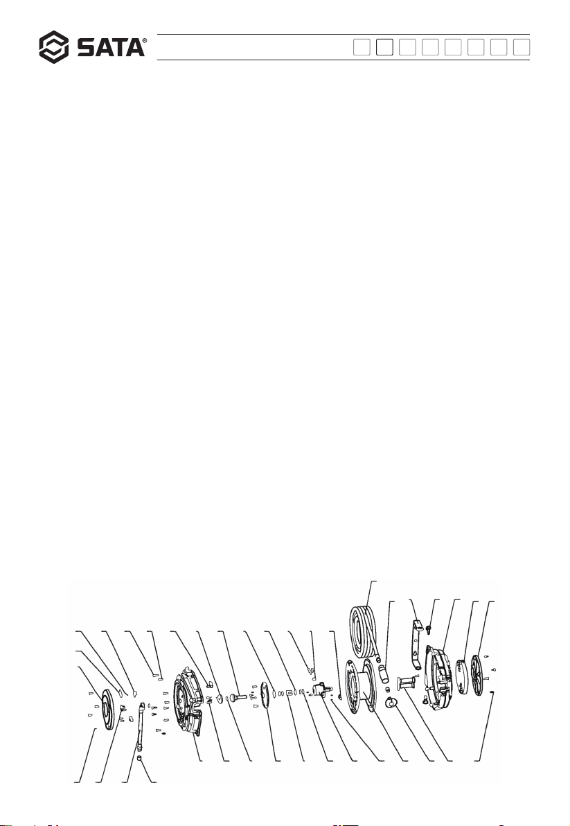
序号 SATA 配件号 配件中文品名 数量 /套 适用型号
1 P98001-1G 上壳 1 98001, 98002 共用
2 P98001-2G 丁腈胶 O形圈 28.24*2.62 1 98001, 98002 共用
3 P98001-3G 上盖 1 98001, 98002 共用
4 P98001-4G 丁腈胶 O形圈 9.19*2.62 2 98001, 98002 共用
5 P98001-5G 连接座 1 98001, 98002 共用
6 P98001-6G 丁腈胶 O形圈 10.77*2.62 1 98001, 98002 共用
7 P98001-7G 十字槽盘头自攻螺钉 ST3.5*16F 6 98001, 98002 共用
8 P98001-8G 弯板 1 98001, 98002 共用
9 P98001-9G 挡座 1 98001, 98002 共用
10 P98001-10G 挡片 1 98001, 98002 共用
11 P98001-11G 钢板弹簧 1 98001, 98002 共用
12 P98001-12G 阀体 1 98001, 98002 共用
13 P98001-13G 铝阀芯 1 98001, 98002 共用
14 P98001-14G 下盖 1 98001, 98002 共用
15 P98001-15G 丁腈胶 O形圈 13.94*2.62 4 98001, 98002 共用
16 P98001-16G 下壳 1 98001, 98002 共用
17 P98001-17 10m ID6mm 管总成 1用于 98001
17 P98002-17 15m lD6mm 管总成 1用于 98002
18 P98001-18G 十字槽盘头自攻螺钉 ST4.2*13F 5 98001, 98002 共用
19 P98001-19G 十字槽盘头自攻螺钉 ST4.2*16F 14 98001, 98002 共用
20 P98001-20G 1m lD6mm 导入管总成 1 98001, 98002 共用
21 P98001-21G 十字槽盘头自攻螺钉 ST2.9*13F 4 98001, 98002 共用