ECOVENT USA EV-SHT User manual

ECOVENT USA CHIMNEY MODEL EV-SHT
5"-8" DIAMETER INSTALLATION INSTRUCTIONS
A MAJOR CAUSE OF CHIMNEY RELATED FIRES IS FAILURE TO
MAINTAIN REQUIRED CLEARANCES (AIR SPACES) TO COMBUSTIBLE
MATERIALS. IT IS OF THE UTMOST IMPORTANCE THAT THIS CHIMNEY
BE INSTALLED ONLY IN ACCORDANCE WITH THESE INSTRUCTIONS.
Read through all these instructions before beginning your installation. Failure
to install the chimney as described in these instructions will void the
manufacturer’s warranty and may have an effect on your homeowner
insurance and UL listing status. Keep these instructions for future use.
EcoVent USA, LLC
600 Broadway Street
Joplin, MO 64801
Tel: 214.929.1152
info@ecoventusa.com
www.ecoventusa.com

CONTENTS
CLEARANCES. ................................................................................................1
PERMITS..........................................................................................................1
MODEL EV-SHT APPLICATIONS ...................................................................1
CHIMNEY DIAMETER......................................................................................1
CHIMNEY HEIGHT...........................................................................................1
CHIMNEY PLACEMENT. .................................................................................2
CHIMNEY ENCLOSURE REQUIREMENTS ....................................................2
COLD CLIMATE…........................................................................................... 2
STOVE RECOMMENDATIONS. ......................................................................3
STEP-BY-STEP DIRECTIONS.........................................................................3
CEILING SUPPORTED ....................................................................................3
OFFSET ELBOW INSTALLATION ...................................................................8
ROOF BRACE INSTALLATION .......................................................................9
ROOF SUPPORTED INSTALLATIONS .........................................................12
TEE-SUPPORTED INSTALLATIONS ............................................................14
MASONRY FIREPLACE INSTALLATIONS........................................................ 19
ZERO-CLEARANCE FIREPLACE INSTALLATIONS.....................................20
CHIMNEY MAINTENANCE ............................................................................21

1"
CLEARANCES
Always allow at least a 2-inch clearance between Model EV-SHT chimney
pipe and any combustible materials. Never fill any required clearance space
with insulation or any other materials. Combustible materials include lumber,
plywood, sheetrock, plaster and lath, furniture, curtains, electrical wiring and
building insulation. Keep single wall stovepipe at least 18 inches away from
combustible materials, unless a clearance reduction system that is acceptable
to the authority having jurisdiction is used, or the appliance to be installed is
listed and the instructions specify a different clearance.
PERMITS
Contact your local Building Official or Fire Official regarding permits,
restrictions, and installation inspections in your area.
Model EV-SHT APPLICATIONS
Model EV-SHT chimney is UL 103 Type HT insulated chimney, which can be
used with wood stoves, fireplaces, fireboxes, furnaces, boilers, water heaters,
stoves, ranges, or other residential-type appliances fueled by oil, gas, coal, or
wood, that require a chimney system. Do not use with forced draft, positive-
pressure appliances.
CHIMNEY DIAMETER
Follow the appliance manufacturer’s instructions to determine chimney
diameter and clearances between combustible materials and your heating
appliance. Never choose a chimney with an inside diameter smaller than your
appliance's outlet. To calculate the chimney’s outside diameter, add 2 inches
to the inside diameter.
CHIMNEY HEIGHT
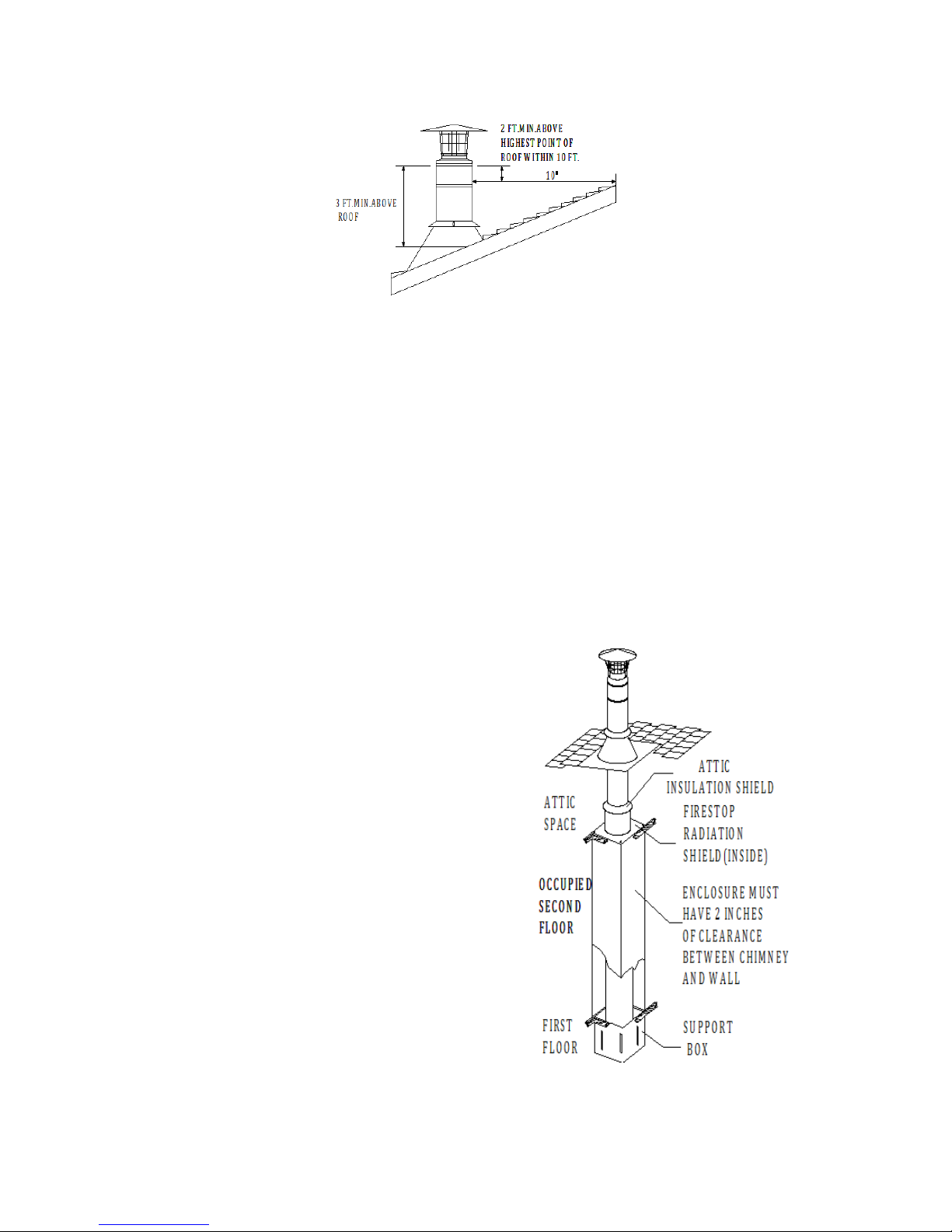
The National Fire Protection Association Standard #211 states: “Chimneys
shall extend at least three feet above the highest point where it passes through
the roof of a building, and at least two feet higher than any portion of a building
within ten feet.” (Fig 1) If the chimney extends more than 5 feet above the roof,
a Roof Brace must be used (see page 9). Due to the overlap of the joints,
subtract 1-1/8 inches from each Chimney Section’s height to calculate installed
height.
The chimney shall at least 10 feet to adjacent walls or buildings.
2"
Fig.1
The Tee Support can hold a maximum of 50 feet of Rainbow Chimney. The
required parts and general configuration are as shown in Figures 21 and 22.
CHIMNEY PLACEMENT
When deciding the location of your chimney, try to avoid modifications to roof
beams and other structural components of the building.
CHIMNEY ENCLOSURE REQUIREMENTS
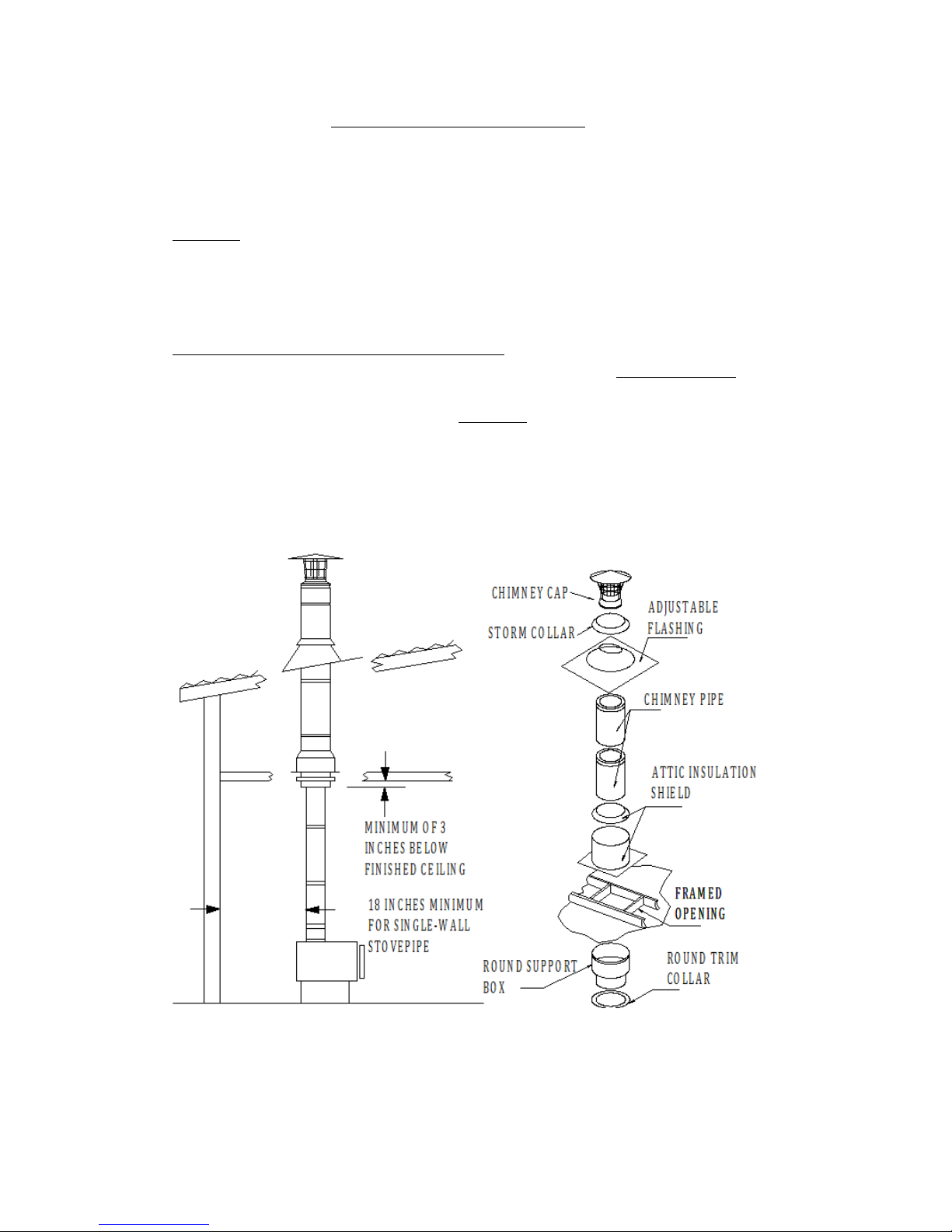
Through Rooms: Interior chimneys shall be enclosed where they extend
through closets, storage areas, occupied spaces, or any place where the
surface of the chimney could be contacted by persons or combustible
materials. The space between the outer wall of the chimney and the enclosure
shall be at least 2 inches (Fig 2).
Multi-Story: Consult local building codes
for requirements in your area. In the
U.S., the National Fire Protection
Association Standard #211 states:
"Factory-built chimneys that pass through
floors of buildings requiring the protection
of vertical openings shall be enclosed with
approved walls having a fire resistance
rating of not less than one hour when such
chimneys are located in a building less
than 4 stories in height, and not less than 2
hours when such chimneys are located in a
building more than 4 stories in height.” In
Canada, except in single-family and two
family dwellings, chimneys which extend
through another story must have an
enclosure with a fire resistance rating
equal to or greater than that of the floor or
roof assembly through which they pass.
Fig.2

3"
Cold Climates: In cold climates, chimneys mounted on an outside wall should
be enclosed in a chase. Exterior chases reduce condensation and creosote
formation, and enhance draft. Include an access door by the Tee Cap for
chimney cleaning (Refer to Fig 21, page 16).
STOVE RECOMMENDATIONS
Follow the stove manufacturer’s instructions. The requirements stated below
pertain to all stoves or other appliances installed with Model EV-SHT systems.
Choice: Choose an appliance that is listed by a recognized testing laboratory,
is appropriate for your needs, and is not larger than required.
Installation: Once the chimney system is in place, install the stovepipe to
connect the appliance to the chimney as described in the appliance
manufacturer’s instructions. Be sure to maintain all required clearances.
Flues: Connect only one solid fuel appliance per chimney.
Operation: Follow the appliance manufacturer’s instructions for maximum
efficiency and safety. Over firing can damage the appliance, stovepipe and
chimney.
Fuels: Do not burn driftwood, plastic, or chemically treated wood such as
railroad ties. They are corrosive to your appliance, stovepipe and chimney.
Follow the appliance manufacturer’s instructions and safety manual in regards
to fuels. Not all appliances are equipped to burn coal. Coal with a low sulfur
content will reduce the possibility of corrosion.
Mobile Homes: Please read the appliance manufacturer’s instructions and
safety manual carefully. Not all appliances are listed for use in mobile homes.
STEP-BY-STEP DIRECTIONS
There are four general types of EV-SHT installations:
1.
Ceiling-supported
2.
Roof-supported
3.
Tee-supported (through-the-wall)
4.
Masonry Fireplace
5.
Zero-clearance Fireplace
Review the step-by-step directions before beginning your installation.
CEILING SUPPORTED
1. Place Appliance: Position the appliance according to the manufacturer’s
instructions. The flue outlet collar should be placed between the rafters or
joists above, if possible.
2. Frame Support Opening: Drop a plumb bob to the center of the
appliance’s flue outlet and mark this center point on the ceiling. Refer to Table
1 for specific framing and clearance dimensions. Mark appropriate cutting lines
around the center point. Cut a square hole in the ceiling for the Support Box.
Frame a level, square opening centered over the hole which you have cut.
(Figure 3 and 4).
4"
3. Install Support: For installation into a flat ceiling, you may use either the
Round Support Box or the Square Ceiling Support Box. For the Square Ceiling
Support Box, refer to the Square ceiling installation below. The Round Ceiling
Support Box has the option of a square or round Trim Collar available (Fig 5).
The bottom of the Round Support Box must extend at least 3 inches below the
finished ceiling. Level the Support Box and secure it to the framing using at
least three 8-penny nails per side (min. of 12 total ). Alternatively, you may use
1-1/2" #8 wood screws (min. of 12 total), instead of nails. Next, secure the Trim
Collar (round or square) to the framing members using provided hardware (Fig
6).
For installation into a cathedral ceiling, you must use the Square Ceiling
Support Box and the two-piece Trim. The bottom of the square portion of the
Support Box must be a minimum of 2-inches lower (round portion is an
additional 3 inches lower) than the finished ceiling at the lowest side of the
penetration (Fig 5 & 6). Level the Support Box and secure it to the framing
using at least three (3) 8-penny nails per side (minimum of 12 nails total), or a
minimum of (3) #8, 1-1/ 2" wood screws. Adjust the overlapping "U-shaped"
Trim pieces so they cover the Support Box, and secure them to the framing
members using provided hardware
Fig.3

5"
Fig.4
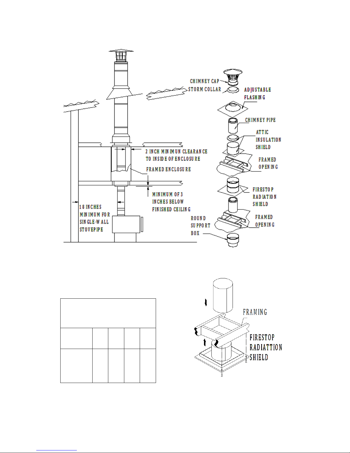
4. Frame Openings: Frame openings in each ceiling or floor above the
Support Box (Fig 7). These openings are to hold the Radiation Shield and Attic
Shield. Locate each opening by dropping a plumb bob to the four corners of
the opening below. Maintain the minimum clearances and dimensions as
specified in Table 1. If Elbows must be used to avoid an obstruction, refer to
the Offset Elbow Installation section.
Fig.5 Fig.6
5. Cut Roof Opening: Cut an opening in the roof directly above the opening
below, and at least 4 inches larger than the chimney’s outside diameter to
provide at least a 2-inch clearance all around the chimney. The chimney must
be centered within this opening and maintain the 2-inch clearance to
combustibles.
6. Install Radiation Shield: A Radiation Shield is required in multistory
installations at each floor penetration above that where the Support Box is
located when the attic insulation shield is to be enclosed. Example: in a
multistory home where the appliance is on the ground floor (Support Box is in
the 1st floor ceiling), you would need a Radiation Shield at the 2nd floor ceiling,
and at the 3rd floor ceiling, etc., including where the chimney penetrates into
the attic. Figure 7 shows a typical 2-story installation with an attic. Note: a
Radiation Shield is not installed where the chimney penetrates through the roof.
The Radiation Shield is installed on the underside of the ceiling/floor framing,
with the cylindrical "tube" portion of the shield pointing upward (Fig 8). Use a
minimum of either (1) 8 penny nail or (1) #8, 1-1/2” wood screws per corner.
Refer to Table 1 for framing requirements.
6"
Fig.7
Table 1
Fig.8
FRAME" DIMENSIONS" FOR" SQUARE" CEILING" SUPPORT" BOX,"
ROUND" CEILING" SUPPORT" BOX," WALL" THIMBLE," AND"
RADIATION"SHIELD
"
CHIMNEY"SIZE
"
5”"
6”"
7”"
8”"
FRAMED"
OPENING"INSIDE"
DIMENSIONS
"
11"1/2
"
X"
11"1/2
"
12"1/2
"
X"""12
"
1/2
"
13"1/2
"
X"""13
"
1/2
"
14"1/2
"
X"""14
"
1/2
"

7"
7. Assemble Chimney Sections: Lower the female end of the first Chimney
Section in the Support Box (Fig 9). It will twist-lock clockwise onto the male
end of the Support Box. Turn Pipe Sections firmly clockwise to lock them
together. Sheet metal screws are not required, but they may be used to
reinforce the connection, if desired. Use only 1/2" (or shorter) sheet metal
screws. Do not penetrate the inner liner of the chimney.
Fig.9 Fig.10
8. Install Attic Insulation Shield (when the attic insulation shield is to be
enclosed): Install the Attic Insulation Shield where the chimney passes into an
attic. Its purpose is to prevent debris and insulation from getting too close to
the chimney (Fig 10). An installed Attic Insulation Shield is 15 inches high. In
attic areas where this shield cannot fit, you must enclose the attic portion of the
chimney in a framed enclosure. If the chimney is fully enclosed through the
attic, an Attic Insulation Shield is not required. If the chimney passes into the
attic, install the Attic Insulation Shield as follows:
a. If the Radiation Shield extends above the attic floor, no modifications are
necessary. The Radiation Shield will fit inside the Attic Insulation Shield.
b. Assemble Chimney Sections until at least 18 inches of chimney extends
above the Radiation Shield.
c. Extend the Radiation Shield tube extension (keep at least 1" overlap), and
secure in place using sheet metal screws.
d. Slip the Attic Insulation Shield over the Chimney and Radiation Shield until
the base sits squarely on the framed opening (Fig 7 & 10).
e. Secure the Attic Insulation Shield to the top of the framed opening using at
least (3) 8-penny nails or (3) #8, 1-1/2" wood screws per side (Fig 10).
f. Wrap the Collar of the Attic Insulation Shield around the chimney and fasten
it loosely with supplied hardware. Slide the Collar down to meet the Attic
Insulation Shield. Tighten the hardware to secure theCollar.
9. Attach Flashing: In new construction, assemble the Chimney Sections to a
point above the roof, then slip the Flashing over the chimney. On an existing
roof, center and install the Flashing before extending the chimney above the
roof. Allow space to permit sliding the next Chimney Section up through the
8"
Flashing. Always insure the chimney remains vertical (use level), and that at
least a 2-inch clearance to combustible materials is maintained all around.
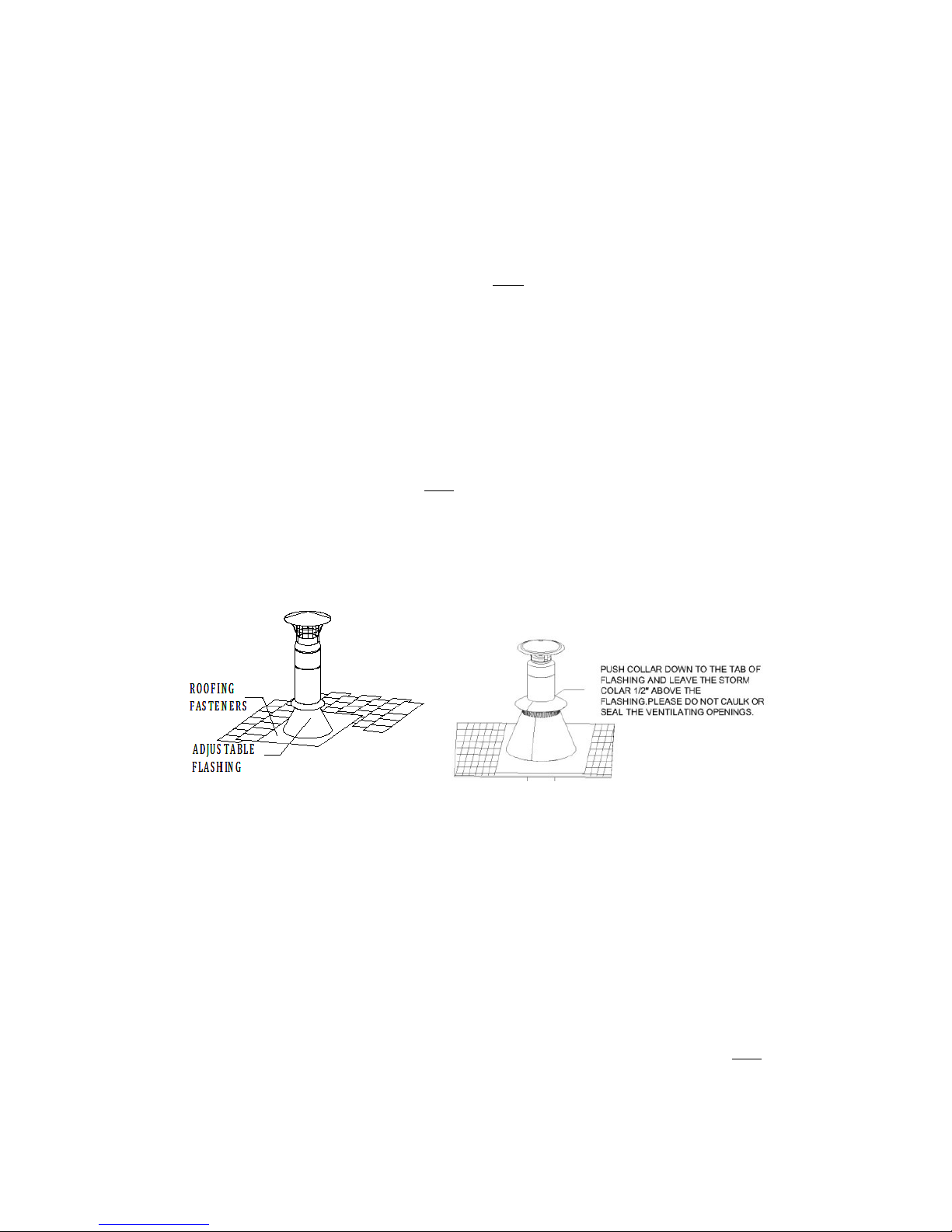
Install the upper edge of the Flashing under the roofing. Nail to the roof along
the upper edge and down each side with 1-inch roofing nails. Do not nail the
lower edge of the Flashing (Fig 11). Be sure to follow local building practices,
as needed. Seal all nail heads with a non-hardening waterproof sealant. On
flat or tarred and graveled roofs, nail and seal the Flat Roof Flashing to the roof
on all sides with roofing compound. Do not put screws through the Flashing
into the Chimney Pipe.
10. Finish Top: Apply a high-temperature (5000F), non-hardening waterproof
sealant around the chimney at the point where the Storm Collar will meet the
chimney just above the Flashing 1/2 INCH. (Figures 11 and 12). Slide the
Storm Collar down over the chimney to the tab of the Flashing. Tighten and
seal the Storm Collar against the sealant. After installing sufficient Chimney
Sections to meet the height requirement (Fig 1), attach the Chimney Cap onto
the top of the chimney by holding the collar of the cap and twist locking it
clockwise onto the chimney. Do not hold upper portion of the cap and twist, as
this may damage the cap. The Chimney Cap can be removed for chimney
cleaning as described in the Chimney Maintenance section of the instructions.
Use a Roof Brace if the chimney extends more than 5 feet above the roof
(Figures 14 & 15 in the Roof Brace).
Fig"11"Fig"12"
11. Enclosures: Enclose chimneys where they pass through occupied spaces,
including closets. Always maintain at least a 2-inch clearance between the
chimney and any combustible materials. Interior enclosures may be
constructed with standard framing and sheathed with sheetrock or plywood.
Use Wall Brackets as needed to maintain a minimum of 2 inches of air space
between the chimney and combustible materials.
OFFSET ELBOW INSTALLATION
Elbows are manufactured in 15° and 30° angles measured from the vertical. A
30° Elbow is the largest that can be used in an offset. A 30° Elbow may not be
combined with a 15° Elbow to make a 45° offset. Avoid Elbows if possible,
since a totally vertical chimney is more efficient. When Elbows are necessary

9"
to avoid obstructions such as rafters, ridgepoles, or joists, use no more than
two 30° offsets in any one chimney system.
1. Attach Elbows: Attach Elbow to Chimney Section or other Elbow. Please
be noticed that the female end of the elbows are not lanced, in order to ensure
proper alignment of the chimney system can be maintained. Locking bands
must be used at all chimney joints. Attach one Elbow to the Chimney Section
below, and align it for the offset. Refer to Table 2 to determine the required
offset length and attach an appropriate length (or lengths) of Chimney
Section(s) above the Elbow. The maximum length of chimney pipe between
elbows is not to exceed 72" (maximum of two chimney sections only). Attach
the second Elbow above the Chimney Section to complete the offset (Fig 13).
2. Secure Offset: Place the Elbow Strap’s band around the angled portion of
the top Elbow, then tighten the nut and bolt until the clamp is firm. Wrap the
Elbow Strap end over an adjacent joist or rafter and secure it with at least (2)
8-penny nails or (2) #8, 1-1/2 screws. Do not add more Chimney Sections until
the Elbows are supported. Be sure that the chimney remains vertical. If there is
more than one Chimney Section between the Elbows, install a second Elbow
Strap around the joint of the two Chimney Sections (Fig13).
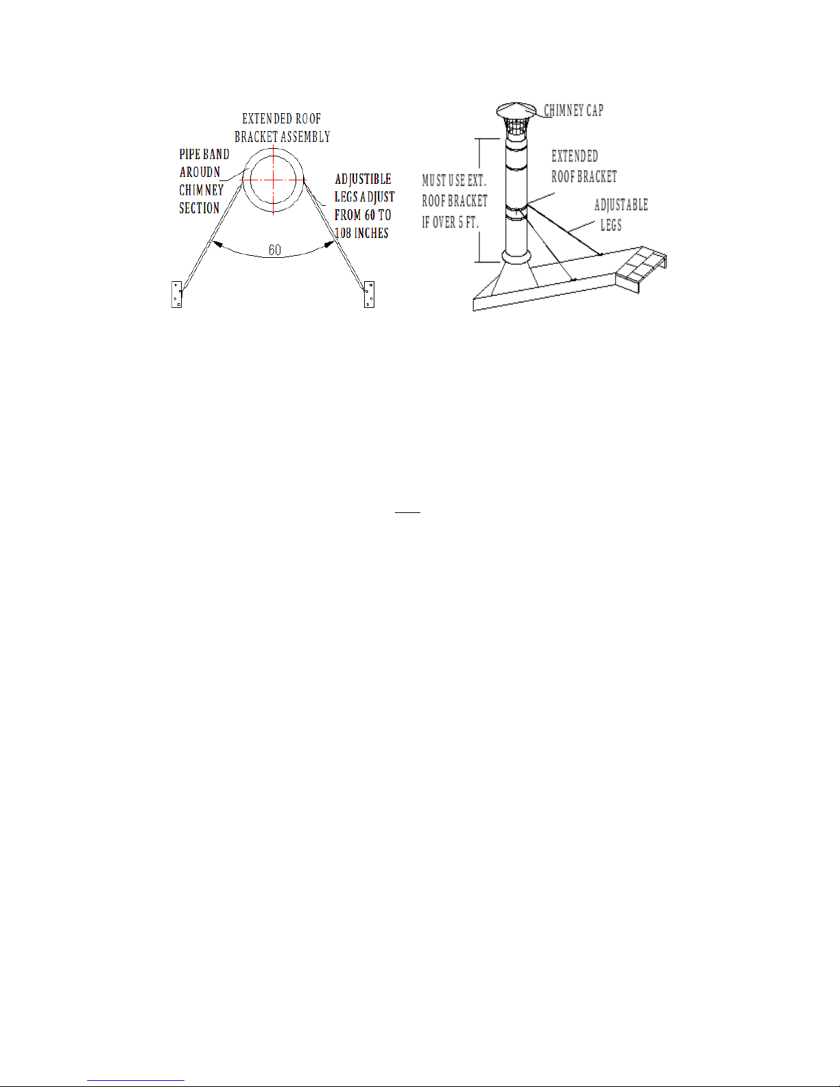
ROOF BRACE INSTALLATION
If the chimney extends more than 5 feet above the roofline, a Roof Brace must
be installed at every 5-foot increment of chimney height above the roofline,
leaving no more than 5 feet of chimney extending above the last Roof Brace.
The Roof Brace consists of the Pipe Band, the Adjustable Legs, and the Roof
Brackets.
Fig"13"

10"
1. Mount Pipe Band: Slip the Pipe Band around the chimney and secure by
tightening the nut and bolt.
2. Attach the Legs: The Adjustable Legs of the assembly will adjust from 60"
to 108". Secure one end of the Legs to the Pipe Band using the nuts and bolts
included (1 per Leg). Position the Adjustable legs so they form approximately a
60° angle with the chimney, and with each other (Figures 14 and 15). Be sure
that there is at least 3" of overlap between the top and bottom halves of the
Adjustable Leg. In order to secure Legs in proper position, there is a hole
provided in the outer leg where the outer and inner halves overlap. Use a 1/4"
drill bit to drill through the inner leg at that location. Use the nut & bolt provided
to pin the Adjustable Legs in position.
3. Install Roof Bracket: Mount the two Roof Brackets where each of the
adjustable Legs meets the roof, using (6) 1" roofing nails per bracket. Seal the
nail heads carefully with a non-hardening, waterproof sealant. Attach the
bottom end of the Adjustable Legs to the Roof Brackets using the nuts & bolts
provided.
CHIMNEY
LENGTH
BETWEEN
ELBOWS
5
6
7
8
OFFSET
RISE
OFFSET
RISE
OFFSET
RISE
OFFSET
RISE
ELBOW DEGREE =
15
0
1 29/64
12
6/64
1 29/64
12 16/64
1 32/64
12 33/64
1 34/64
12 48/64
6
2 62/64
17 51/64
3
17.94277
3
2/64
18 14/64
3
4/64
18 29/64
12
4 32/64
23 32/64
4 33/64
23.64705
4 36/64
23 59/64
4 38/64
24 10/64
18
6
2/64
29 13/64
6
3/64
29.35134
6
6/64
29 40/64
6
8/64
29 55/64
24
7 36/64
34 58/64
7 37/64
35.05563
7 39/64
35 21/64
7 41/64
35 36/64
30
9
6/64
40 39/64
9
7/64
40.75991
9
9/64
41
2/64
9 11/64
41 17/64
36
10 40/64
46 20/64
10 41/64
46.4642
10 43/64
46 47/64
10 45/64
46 63/64
42
12
9/64
52
1/64
12 11/64
52.16849
12 13/64
52 28/64
12 15/64
52 44/64
48
13 43/64
57 46/64
13 44/64
57.87277
13 47/64
58
9/64
13 49/64
58 25/64
ELBOW DEGREE =
30
0
3
7/64
12 46/64
3 15/64
13 10/64
3 25/64
13 50/64
3 27/64
13 60/64
6
6
4/64
17 53/64
6 11/64
18.25035
6 23/64
18 58/64
6 25/64
19
4/64
12
9
1/64
22 61/64
9
8/64
23.36467
9 20/64
24
1/64
9 22/64
24 11/64
18
11 62/64
28
4/64
12
5/64
28.47899
12 17/64
29
9/64
12 19/64
29 18/64
24
14 59/64
33 11/64
15
2/64
33.59332
15 14/64
34 16/64
15 16/64
34 26/64
30
17 56/64
38 18/64
17 63/64
38.70764
18 10/64
39 23/64
18 13/64
39 33/64
36
20 53/64
43 26/64
20 60/64
43.82196
21
7/64
44 31/64
21 10/64
44 40/64
42
23 50/64
48 33/64
23 57/64
48.93629
24
4/64
49 38/64
24
7/64
49 48/64
48
26 47/64
53 40/64
26 54/64
54.05061
27
1/64
54 45/64
27
4/64
54 55/64
TABLE 2 ELBOW OFFSET CHART
11"
ROOF SUPPORTED INSTALLATIONS
There are two types of Roof Supported Installations: (1) Using a roof jack, and
(2) Using a Roof Support.
(1)
For a roof jack installation, make sure that the square box portion of the
Support Box can extend at least 2" below the low side of the finished ceiling
(Fig 16). The roof jacket must remain level, and the top edge of the box must
cover the edge of the roof’s decking material. Mobile home chimney
installations are roof supported. Do not seal openings in flashing.
1. Place Appliance: Place the appliance in its proper location, referring to the
manufacturer’s instructions as to allowable distances from combustibles, etc.
2. Cut Openings: Cut a roof opening in your desired location, just as in a
Ceiling Supported Installation (Steps 1 through 5, page 4 – 6). If a separate
ceiling and roof exists, as shown in Figure 17 (Low Attic), first cut and frame a
ceiling opening as described in Ceiling-Supported Installations (Step 2). Refer
to Table 1 for clearance and framing specifications. If it is desired to install
through a cathedral ceiling (Fig 16), then the hole is cut in the roof.
3. Install Roof jack: Slip the roof jack into the framed opening so the square
portion projects at least 2 inches below the finished ceiling and rafters (bottom
of round portion is 5" below), and extends above the ceiling to framing or
decking materials that it can be nailed to. Level the roof jacket, and slit the
corners to the roofline where they extend beyond it. Using 8-penny nails, or 1-
1/2", #8 screws, per side (Fig 20). Screw the trim sections into the ceiling (Fig
6). Roof jack must extend from the roof line 6inches.
4. Complete Installation: Refer to Steps 7, 9 & 10 in the Ceiling Supported
Installation section to complete the Roof Supported installation.
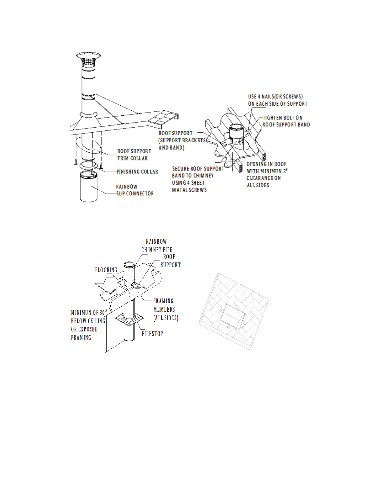
(2)
A Roof Support is used in installations where there is a cathedral ceiling,
and a Square Ceiling Support is not desired. The Roof Support allows the EV-
HST to come down into the room below the level of the ceiling (Fig 18). The
Roof Support can support a maximum of 45 feet of EVHST total, and
maximum of 20 feet below the support.
1. Cut and frame opening to provide a minimum 2" clearance on all sides of the
Fig"14"
Fig"15"

12"
chimney pipe.
2. Bolt on the Roof Support Brackets to the Roof Support Band using the
supplied hardware. Attach the Roof Support Brackets to roof using (4) 8 penny
nails or (4) #8, 1-1/2” screws per side (Fig 18).
Fig"16"
"
"
3. Determine how much EV-HST chimney will be extending into the room
(minimum of 3" below the ceiling). Be sure to maintain the proper clearance to
combustibles (walls and ceilings) for the connector pipe. Once you have
identified the proper height for your installation, attach the Roof Support Band
to the Chimney Section by tightening the Bolt, and secure it with supplied
hardware.
4. Attach desired length of Chimney Sections above and below the roof level
(max. of 45' total, 20' below the support) (Fig 18).
5. Refer to Steps 10 & 11 in the Ceiling Supported Installation section (page 8,
9) to complete the Roof Supported installation.
Alternative Installation Location for Roof Support: The Roof Support may be
used at the bottom of a Chimney installation (Fig 19). This may be useful for
some basement installations. Maintain a minimum of 2” clearance to
combustibles at all times. The EV-HST chimney needs to extend a minimum of
3” below the finished ceiling or exposed framing members. Please note that
you cannot extend the chimney all the way to the appliance – you must have
some connector pipe.

13"
1. Cut and frame opening to provide a minimum of 2" clearance on all sides of
the chimney. Be sure to maintain the proper clearance to combustibles for the
connector pipe
2. Bolt on the Roof Support Brackets to the Roof Support Band. Attach the
Roof Support Brackets to floor (Fig 19).
3. Determine how much EV-HST chimney will be extending into the room
(minimum of 3" below the framing), and attach the Roof Support Band to the
Chimney Section by tightening the Bolt, and secure it with supplied hardware
(Fig 18 & 19).
4. Install the specialized Firestop below the finished ceiling or framing
members. The Firestop can only be used when installed with the Roof Support
in this type of installation. Use a standard Radiation Shield at all other locations.
5. Follow steps 4, 5 for the Roof Support Installation (page13).
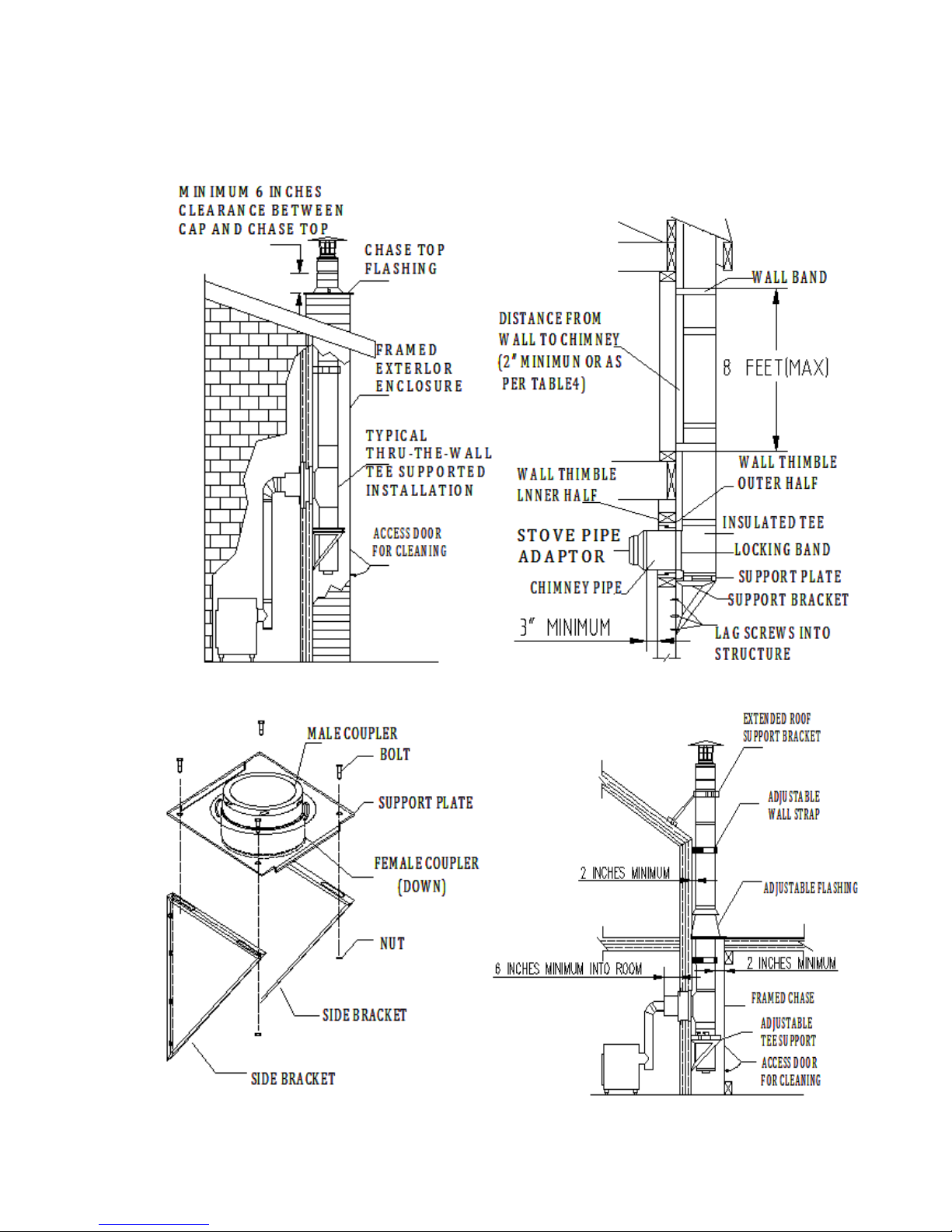
TEE-SUPPORTED INSTALLATIONS
Tee-Supported installations are used when passing through a wall to an
outside chimney. The Tee Support can hold a maximum of 50 feet of ev-HST
chimney. The required parts and general configuration are as shown in Figures
21 and 22.
Fig"17"
14"
1. Place Appliance: Position the appliance according to the manufacturer’s
instructions. It is a good idea to try to position the appliance so it will allow the
chimney to line up centered between studs.
2. Locate, Cut & Frame Opening: Determine the location where the chimney
will pass through the wall. The chimney should pass through the wall, centered
between two studs. The height of the penetration can be determined by
positioning sections of stove pipe until you have the desired configuration
(refer to the appliance manufacturer's installation instructions for restrictions
Fig"18"
Fig"19"
Fig"20"
15"
on stove pipe). Cut and frame an opening in the inner and outer walls at this
location. Refer to Table 1 (page 7) for the appropriate framing dimensions.
Fig"21"Fig"22"
"
Fig"23"
Fig"24"

16"
3. Install Wall Thimble: From the outside wall, put the outer half of the Wall
Thimble in the opening. Center the outer half of the Wall Thimble. Secure the
Wall Thimble to the outside wall with at least (4) 8 penny nails or (4) #8, 1-1/2”
screws. For concrete wall, Wall Thimble is not needed. The hole on the wall
just needs to be slightly larger than the chimney. Install the inner half (with
round plate) of the Wall Thimble in the inside wall surface, ensuring that the
shield slides into the shield of the outer half. Secure the Wall Thimble to the
inside wall with at least (4) 8 penny nails or (4) #8, 1-1/2”screws
4. Install Wall Support, Tee and Tee Cap: Assemble the Wall Support
(Figure 23) by attaching the 2 side brackets to the support plate, with the
hardware supplied (female coupler of the insulated coupling section is down).
Install one 6” Chimney Section (or longer as required) to the horizontal branch
of the insulated tee. Lock securely into the tee by twisting clockwise. A locking
band must then be installed at this connection. Make sure the clamp is facing
down to prevent any water from collecting in the lockingband.
From outside the building, slide the chimney length (previously installed on a
tee) through the wall thimble ensuring the male coupling on a tee is facing
upward.
Install the male coupler of insulated coupling section on the support plate into
the female coupler of the Tee. Lock securely into the tee by twisting clockwise.
Place the assembled wall support against the wall (plate up) directly below the
insulated coupling section of the Wall Support. Tighten the insulated coupling
section and the support plate with supplied lag screws (14#, 2”). Then secure
the whole Wall Support assembly onto wall using 14#, 2” wood screws
through the pre-punched slots in each bracket. Important: Verify that Wall
Support is level, and secure the leg brackets of the Tee Support to the wall
(Figs 24). Finally, install Tee Cap into the female coupler of the insulated
coupling section. Lock securely by twistingclockwise.
5. Complete Chimney: Attach the Chimney Sections as in Step 7 in the
Ceiling Supported Installation section (page 7). Secure the chimney to the wall
with Wall Straps at a minimum of 8-foot intervals and maintain at least 2 inches
of clearance to combustible materials. Slip the Wall Straps around the chimney,
tighten the bolts, adjust the clearance, and fasten the Wall Straps to the wall
Once the chimney is at the minimum height specified in Figure 1, attach the
Chimney Cap onto the top of the chimney by holding it by the collar and twist
locking it clockwise onto the Chimney Pipe. If the chimney penetrates an
overhang, frame for at least 2 inches of clearance, and install Flashing and
Storm Collar as described in Steps 9 & 10 for Ceiling Supported Installations
(page 8). Another option is to cut away the overhang for a 2-inch clearance
(Fig 25). If the chimney extends more than 5 feet above the top Wall Strap or
Flashing, use a Roof Brace.
6. Install Chase Top Flashing: It is recommended that a Tee Supported
Chimney be enclosed in a chase. If a chase enclosure has been constructed,
you can either use a standard flat-roof flashing, or you can use a Chase Top
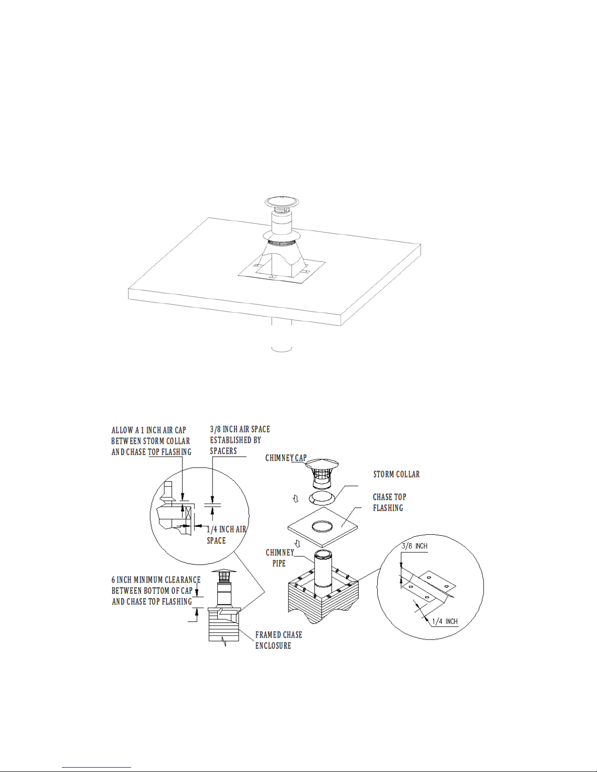
17"
Flashing. Using a Chase Top Flashing allows for a lower profile for the
chimney. The Chase Top Flashing has an opening that is 3" larger in diameter
than the EV-HST chimney. If the Chase Top Flashing can fit over your chase
enclosure as required (Fig 26) then install as directed, or trim as needed.
However, if the Chase Top Flashing is smaller than your chase enclosure, you
will need to provide a galvanized sheet capable of covering your chase and
overhanging the sides by 1/2 - 3/4 inch. Attach the Chase Top Flashing to the
Fig"25"
Fig"26"

18"
galvanized sheet using appropriate sheet metal screws and non-hardening
waterproof sealant. Use the Chase Top Flashing Spacers to allow the proper
air-gap clearances on the galvanized sheet. The Chase Top Flashing Spacers
are available to insure that the proper air-gap is maintained. Figure 26 displays
in some detail, how these air gaps are established using the Spacers and
Chase Top Flashing. Secure the Chase Top Flashing to the chase using a
sufficient number of #8, 1-1/2" wood screws, being careful to insure the air gap
is maintained between the flashing and the chase. Seal the screw heads with
non-hardening sealant. When installing the Storm Collar, allow a 1" air space
between the bottom of the Storm Collar and the Chase TopFlashing.
MASONRY FIREPLACE INSTALLATIONS
1. Determine Chimney Size: Use Table 3 to determine the correct diameter
chimney for your fireplace.
2. Mount Anchor Plate: Chimneys for masonry fireplaces begin with an
Anchor Plate. Make sure the surface of the masonry chimney has a level
surface on which to attach the Anchor Plate. If the top of the masonry does not
have a level surface, then you will need to modify the masonry accordingly.
Center the Anchor Plate over the masonry flue opening, and seal the Anchor
Plate with a high-temperature (10000F) sealant. Secure Anchor Plate with (4)
1/4" x 2" masonry anchors (Fig 27). It is very important that the Anchor Plate is
level. Be sure to maintain a 1" min. clearance to combustibles from the Anchor
Plate.
3. Attach Chimney: Twist lock the first Chimney Section clockwise onto the
Table"3"
Table of contents


