manuals.online logo
Brands
  1. Home
  2. •
  3. Brands
  4. •
  5. Caple
  6. •
  7. Ventilation Hood
  8. •
  9. Caple SIR900 Guide

Caple SIR900 Guide

Other manuals for SIR900

2

Other Caple Ventilation Hood manuals

Caple BXC910 Manual

Caple

Caple BXC910 Manual

Caple SP600 User manual

Caple

Caple SP600 User manual

Caple BXC610 User manual

Caple

Caple BXC610 User manual

Caple FSCHSS9 User manual

Caple

Caple FSCHSS9 User manual

Caple TSCH601 User manual

Caple

Caple TSCH601 User manual

Caple S-DD2 User manual

Caple

Caple S-DD2 User manual

Caple J129 User manual

Caple

Caple J129 User manual

Caple DD520BK User manual

Caple

Caple DD520BK User manual

Caple BXC611 User manual

Caple

Caple BXC611 User manual

Caple COR540SL User manual

Caple

Caple COR540SL User manual

Caple OM600 User manual

Caple

Caple OM600 User manual

Caple INCHW3 User manual

Caple

Caple INCHW3 User manual

Caple ZC622 User manual

Caple

Caple ZC622 User manual

Caple SC900SS Guide

Caple

Caple SC900SS Guide

Caple AS610BK User manual

Caple

Caple AS610BK User manual

Caple CCH600BK Manual

Caple

Caple CCH600BK Manual

Caple Tela TEL900 User manual

Caple

Caple Tela TEL900 User manual

Caple CGC611 User manual

Caple

Caple CGC611 User manual

Caple ZRC900 User manual

Caple

Caple ZRC900 User manual

Caple CE1500 User manual

Caple

Caple CE1500 User manual

Caple Ceramica CR700 User manual

Caple

Caple Ceramica CR700 User manual

Caple DD903BK User manual

Caple

Caple DD903BK User manual

Caple INCHP3 User manual

Caple

Caple INCHP3 User manual

Caple CGC910BK User manual

Caple

Caple CGC910BK User manual

Popular Ventilation Hood manuals by other brands

Gorenje S3 IHGC963S4X manual

Gorenje

Gorenje S3 IHGC963S4X manual

KOBE ISX2136SQB-1 Installation instructions and operation manual

KOBE

KOBE ISX2136SQB-1 Installation instructions and operation manual

U.S. Products ADVANTAGE-100H Information & operating instructions

U.S. Products

U.S. Products ADVANTAGE-100H Information & operating instructions

Kuppersberg DUDL 4 LX Technical Passport

Kuppersberg

Kuppersberg DUDL 4 LX Technical Passport

Framtid HW280 manual

Framtid

Framtid HW280 manual

Thermador HGEW 36 FS installation manual

Thermador

Thermador HGEW 36 FS installation manual

Electrolux LFT769X user manual

Electrolux

Electrolux LFT769X user manual

AEG X69453MVO UK user manual

AEG

AEG X69453MVO UK user manual

Broan B5836SS manual

Broan

Broan B5836SS manual

Heinner HDCH-6060RGBK quick start guide

Heinner

Heinner HDCH-6060RGBK quick start guide

Baumatic AS35SS instruction manual

Baumatic

Baumatic AS35SS instruction manual

Franke FTF 604 XS V2 Instructions for use and installation

Franke

Franke FTF 604 XS V2 Instructions for use and installation

Best UCB3I30SBW installation instructions

Best

Best UCB3I30SBW installation instructions

Gram EFU 503-90 X instruction manual

Gram

Gram EFU 503-90 X instruction manual

CIARRA CBCS6803 Installation and user manual

CIARRA

CIARRA CBCS6803 Installation and user manual

sauter SHG501 Instructions for installation and use

sauter

sauter SHG501 Instructions for installation and use

Franke 392-17 User instructions

Franke

Franke 392-17 User instructions

FALMEC Polar Black 35 Instruction booklet

FALMEC

FALMEC Polar Black 35 Instruction booklet

manuals.online logo
manuals.online logoBrands
  • About & Mission
  • Contact us
  • Privacy Policy
  • Terms and Conditions

Copyright 2025 Manuals.Online. All Rights Reserved.

D MONTAGE- UND GEBRAUCHSANWEISUNG
GB INSTRUCTION ON MOUNTING AND USE
F PRESCRIPTIONS DE MONTAGE ET MODE DEMPLOI
NL MONTAGEVOORSCHRIFTEN EN GEBRUIKSAANWIJZING
I ISTRUZIONI DI MONTAGGIO E DUSO
E MONTAJE Y MODO DE EMPLEO
P INSTRUÇÕES PARA MONTAGEM E UTILIZAÇÃO
RU ÈÍÑÒÐÓÊÖÈÈ ÏÎ ÓÑÒÀÍÎÂÊÅ È ÏÎËÜÇÎÂÀÍÈÞ
CZ NÁVODNAMONTÁAPOUITÍ
All manuals and user guides at all-guides.com
all-guides.com
6
7
2
3
1
42
3
1
32
1
4
1
4
42
3
5
52
3
1
4
1
4
32
5
1
32
5
84
2
3
5
1
4
1
54
3
2
2
1
4
53
4
5
1
2
3
4
32
5
1
1A 1B
1C 1D
1E 1F
1G 1H
1I 1J
1L
1K
All manuals and user guides at all-guides.com
f
f
gg
j
h
i
g
g
1
2
3
4
5
51
3
2
4
24
1
5
3
1
5
423
42
1
3
5
1
4
5
32
1
2
3
4
5
23
1O 1P
1N
1M
1Q 1R
1S
All manuals and user guides at all-guides.com
q
r
s
t
u
Philips 13W
a
v
v
z
4E
4 A-B-C-D-F-H-I-K-P-Q-
S
4J-4R 4N-O
5G 6L
7M
All manuals and user guides at all-guides.com
1
1
1
3
1
1
x 9
3
x 10
8C 8D - 8I
1
x 4
3
1
1
3
1
x 8
8E
8F - 8G - 8H
8Q
3
x 8
3
x 6
3
x 6
8
All manuals and user guides at all-guides.com
2
2
2
9
7
5
6
B
8
9
4
10
10b
10a
10b
B
11 12
13b
12b
13a
12a
13b
12b
Ø 8mm
7
5
6
B
8
9
4
10Q
6
2
All manuals and user guides at all-guides.com
all-guides.com
20c
B
17L -17
20a
20a
H
20b
20b
G
16
18
B
19
15
17b
17b
17a
B
14
F
15
G
15
14
F
F
15
G
G
13
All manuals and user guides at all-guides.com
22
22
22
19H-J 19L
22
19M
21
18
20
19
All manuals and user guides at all-guides.com
13
Consult the designs in the front pages referenced in the text
by alphabet letters. Closely follow the instructions set
out in this manual. All responsibility, for any eventual
inconveniences, damages or fires caused by not complying
with the instructions in this manual, is declined.
The cooker hood must be placed at a minimum distance of
50 cm from the cooking plane for electric cookers and 65cm
for gas or mixed cookers.The hood can be installed above
these heights but for optimum performance it should be
installed at the distance quoted for the appropriate heat
source.
The hood is equipped with a top air outlet B for discharge
of fumes to the outside (Ducting version  exhaust pipe
and pipe fixing clamps not provided).
Should it not be possible to discharge cooking fumes and
vapour to the outside, the hood can be used in the filter
version, fitting an activated carbon filter and the deflector F
on the support (bracket) G, fumes and vapours are
recycled through the top grille H by means of an exhaust
pipe connected to the top air outlet B and the connection
ring mounted on the deflector F (exhaust pipe and pipe
fixing clamps not provided).
The models with no suction motor only operate in ducting
mode, and must be connected to an external suction device
(not supplied).
Expansion wall plugs are provided to secure the hood to
most types of walls/ceilings. However, a qualified technician
must verify suitability of the materials in accordance with the
type of wall/ceiling. The wall/ceiling must be strong enough
to take the weight of the hood.
Installation
Preliminary information for installation of the hood:
Disconnect the hood during electrical connection, by turning
the home mains switch off.
Remove the fat/s filter/s and the carbon filter frame.
Do not tile, grout or silicone this appliance to the wall. Surface
mounting only. Do not fix chimney flue to furniture or fly over
shelves unless the chimney flue can be easily removed,
in case maintenance is ever required.
Assembling the chimney flue support/bracket (3
parts):
The three parts should be fixed with 4 screws, the support
extension is adjustable and should correspond to the internal
width of the telescopic chimney flue.
Assembling the deflector (only when a deflector
composed of 3 parts is supplied  the deflector should
be only for the filter version):
The three parts should be fixed with 2 screws, the deflector
extension is adjustable and should correspond to the width
of the chimney flue support, to which it is then fixed.
==
X
X
H
=
=
X
F
F
G
G
Only for the models illustrated in Fig. 1D/8D 1E/8E
1Q/8Q
Remove AND CONSERVE the screws that temporarily
fix the flue units (for reasons of transport), the hood
or the flue unit (on the basis of the model possessed)
with the suction unit. The two parts should be
disassembled to facilitate installation. Check how the parts
are fixed together to repeat assemblage at the opportune
moment.
Before fixing the hood to the suction unit check that the metal
band (steam shield) that holds the lamp and the filter/s /
greases is well attached to the front. If necessary adjust the
position ofthe band forwards until the end stop. 
Attention!
The chimney is predisposed for installation of the filter
Version.
In certain models where it is required to use the cooker hood
in the suction version then it is possible to overturn the upper
section of the chimney
and insert it inside the lower section of the chimney so that
the air-exit perforations are not visible. The chimneys in
which this operation is possible are recognizable by their
bracket fixing points G which are repeated also in the lower
side of the upper section of the chimney (see installation
sequence 20a-20b).
Attention! for all pre-assembled models:
the mounting operations 1, 2, 3 should not be taken into
consideration, for installation begin at operation 4.
1. Rest the suction unit on a flat surface and thread the lower
part of the hood onto it (Fig. 1C/8C 1D/8D 1I/8I 1E/
8E 1F/8F 1G/8G 1H/8H 1R/8R 1N 1O 1P 1S).
2. Make all the electrical connections between the two parts
(Fig. 9).
3. Permanently fix the cooker hood to the suction group with
the screws (consult the figure corresponding to the model
in possession)(Fig. 1C/8C 1D/8D 1I/8I 1E/8E 1F/
8F 1G/8G 1H/8H 1R/8R 1N 1O 1P 1S).
4. Using a pencil, draw a line on the wall, extending up to
the ceiling, to mark the centre. This will facilitate
installation (Fig. 10).
5. Rest the drilling template against the wall: the vertical
centre line printed on the drilling template must correspond
to the centre line drawn on the wall, and the bottom edge
of the drilling template must correspond to the bottom
edge of the hood: bear in mind that, when installation is
complete, the underside of the hood must be at least 50
cm above the cooker top in the case of electric cookers,
and at least 65 cm above the cooker top in the case of
gas or mixed cookers.
6. Place the lower support bracket on the perforation
diagram making it coincide with the traced triangle, mark
the two external holes and perforate. Remove the
perforation diagram, insert two wall-dowels and fix the
support bracket of the hood with two 5x45 mm screws
(Fig. 10).
Attention: only the models illustrated in Fig. 1Q/
10Q:
Fix the central bracket with two screws and wall-dowels
above the lower bracket (see perforation diagram for
positioning the holes).
7. Hang the hood onto the lower bracket.
All manuals and user guides at all-guides.com
14
8. Adjust the distance of the hood from the wall.
9. Adjust the horizontal position of the hood.
10. Using a pencil mark the cooker hood permanent drill hole
inside the suction group (1 or 2 fixing points are
necessary for permanent mounting) (Fig. 11).
11. Remove the hood from the lower bracket.
12. Drill at the point marked (Ø8mm) (Fig. 12).
13. Insert 1 or 2 wall screw anchors according to requirement.
14. Apply the flues support bracket G to the wall adherent
to the ceiling, use the flues support bracket as a
perforation diagram (the small slot made on the support
should coincide with the line previously traced on the
wall) and mark two holes with a pencil. Make the holes
(Ø8mm), and insert 2 dowels (Fig. 13).
15. Fix the chimney support bracket to the wall using two
5x45mm screws.
16. Hook the hood onto the bottom bracket.
17. Fix the hood into its final position on the wall
(ABSOLUTELY ESSENTIAL) (Fig. 14).
18. Connect a pipe (pipe and pipe clamps not provided, to
be purchased separately) for discharge of fumes to the
connection ring located over the suction motor unit.
If the hood is to be used in ducting version, the other end
of the pipe must be connected to a device expelling the
fumes to the outside. If the hood is to be used in filter
version, then fix the deflector F to the chimney support
bracket G and connect the other extremity of the pipe
to the connection ring placed on the deflector F (Fig. 15).
19. Connect the electricity.
Attention: only the models illustrated in Fig. 1Q:
Continue from the installation sequence number 23.
20. Apply the chimney stacks and fasten them at the top to
the chimney support G (20b) using 2 screws (20a)
(Fig. 16).
Only for model with optical fibers point lighting
(Fig. 1G):
Check that the chimneys may be removed to permit
access to the optical fibers lamp housing area.
Only for the model with control panel on chimney
flue (Fig. 1L 17):
Insert the command plate from the motor group through
the chimney flue slit from the inside towards the outside
(20c).
Carry out the connection of the control panel to the
command plate.
Attention! The terminal pivot on the plate MUST
correspond to the drill hole on the connection
block situated at the back of the control panel.
21. Slide the bottom section of the chimney down until it
completely covers the suction unit and slots into the
housing provided on top of the hood (Fig. 18).
22. Fix the lower section of the chimney with two screws
(only for the model in Fig. 1H/19H 1J/19J 1L/19L 1M/
19M 1N/19N 1O/19O 1P/19P).
23. Only the models illustrated in Fig. 1Q:
 Put the flues unit on the suction unit.
Connect the electricity between the two parts (Fig.
9).
 Fix the flue units definitively to the suction unit with
the screws (consult the figure corresponding to the
model in possession) (Fig. 8Q).
Attention! Check that the lower section of the flue fits
onto the central bracket (Fig. 20).
 Fix the upper section of the flue units to the flues
support bracket with two screws (Fig. 16).
Remount the carbon filter frame and the fat/s filter/s and check
the perfect functioning of the hood.
Electrical connection
The electrical tension must correspond to the tension noted
on the label placed inside the cooker hood. Connect the
electrical plug, where provided, to the an easily accessible
outlet in conformity with local standards in force.
Where an electrical plug is not provided (for direct connection
to electrical network) place a standards approved bipolar
switch with an aperture distance of not less than 3mm
(accessible) from the contacts.
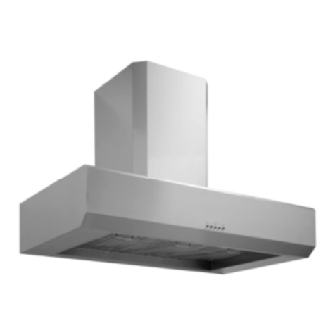
Description of the hood Fig. 1
1 Control panel
2 Grease filter
3 Grease filter release handle
4 lamp
5 Vapour screen
6 Telescopic chimney
7 Air outlet (used for filter version only)
8 point lighting (only for the model in Fig. 1G)
Operation 
All cooker hood versions
Use the high suction speed in cases of concentrated kitchen
vapours. It is recommended that the cooker hood suction
is switched on for 5 minutes prior to cooking and to leave
in operation during cooking and for another 15 minutes
approximately after terminating cooking.
Operation 
Model with button panel
A. on/off light switch
B. on/off aspiration switch and minimum power selection
B+C. medium power selection aspiration switch
B+D. maximum power selection aspiration switch
a. ON/OFF lighting
b. OFF motors
c. d. e. Minimum suction power (c.), medium (d.),
maximum (e.).
f. Operation warning light (where present).
ABCD
a
a b-c de
f
b-c-d-e
b-c-d-e
a
abcde
All manuals and user guides at all-guides.com