manuals.online logo
Brands
  1. Home
  2. •
  3. Brands
  4. •
  5. EcoxGear
  6. •
  7. Marine Radio
  8. •
  9. EcoxGear SOUNDEXTREME SEI-SEMRNGGE User manual

EcoxGear SOUNDEXTREME SEI-SEMRNGGE User manual

Marine
Gauge Radio
Model: SEI-SEMRNGGE
Installation Guide
2
· Please read this Installation Guide and the User Guide before
installation and use. If you are unsure about installing this
product, please contact a professional audio installer.
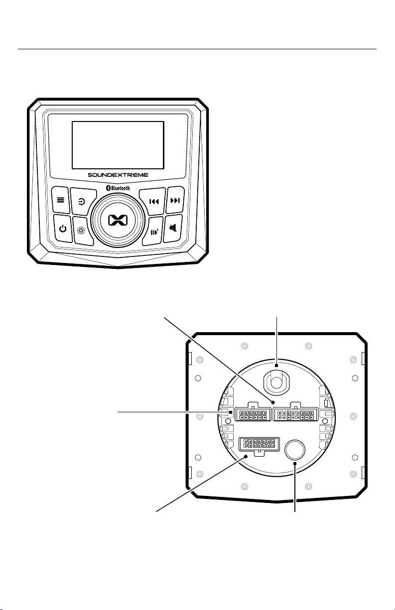
· The Marine Gauge Radio is designed to be installed into a round
opening (refer to Mount Your Marine Radio for details), in boats,
golf carts, cars, and o-road vehicles. Mounting and wiring
may vary for dierent types of vehicles and are called out in this
installation guide.
· When you plan your Radio installation, please ensure that the
mounting surface is flat for best front panel sealing, check for
potential obstacles behind the mounting surface, and confirm that
the mounting surface has adequate clearance around the back of
the Radio for open airflow and for heat ventilation.
· Mount this product securely to prevent damage or injury in
severe conditions.
· BEFORE installation, disconnect any and all negative leads from
the battery’s negative (-) terminal to prevent damage to the unit,
fire, and/or possible injury.
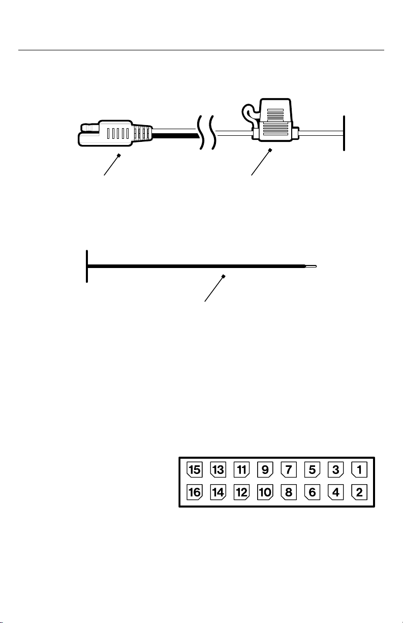
· The Radio requires +12V DC voltage for the power input. If your
vehicle battery power is not 12V (e.g., 24V, 36V, or 48V), you will
need a DC-DC voltage converter with 12V output (e.g. a 48V-to-
12V converter). Connecting the Radio directly to higher voltages
will cause damage to the Radio and VOID THE PRODUCT
WARRANTY.
· The Radio power input has an in-line 35 Amp fuse. Do NOT replace
the fuse with one of a dierent value and never bypass the fuse.
· The Radio has a Remote Turn-On Input feature; this is to ensure
that the Radio is completely powered o (no battery consumption)
when your vehicle is not in use. When the input has a signal
between 12V and 56V, the Radio will turn on. When there is no input
voltage, the Radio will turn o. In general, this Remote Turn-On
signal comes from the vehicle ignition switch.
Important
3
· You will need to connect the (Purple) Remote Turn-On Wire to
the vehicle ignition switch with the supplied (Purple) Remote
Turn-On Extension Cable. If you are not able to connect it to
your vehicle ignition switch, connect this input to a rocker switch
(not included), then connect the rocker switch to a 12V-to-56V
power supply on your vehicle or to a switch accessory panel.
· Alternatively, you can connect the Remote Turn-On Wire,
together with the (Red) Power Wire, directly to the positive
terminal of your vehicle’s battery. When the Radio is o, the
battery consumption is minimal for vehicles whose batteries are
charged multiple times a week.
· The Radio has 3 Power States:
· Powered – When the Radio has 12V power and your vehicle’s
ignition switch (or a rocker switch) is turned on, your Radio
is Powered. When it’s Powered, the Radio may be turned on
(Powered On) automatically or on Standby:
· Turn On (Power On) – When the Radio is in Turn On state, all
functions are accessible.
· Standby – When the Radio is on Standby, it goes into a low-
power consumption (sleep) mode. It turns o the Radio’s LED
Screen and button backlights, and all the functions except the
RF Remote Receiver, so that you can still use the Remote to
turn the Radio on.
· Powered O – When the vehicle’s ignition switch is turned
o, your Radio is Powered O. You will not be able to turn on
your Radio by pressing the Power Button on your Radio or the
included RF Remote Control.
Notes:
· When the Radio is in the Turn On State, you can press the Power
Button on the Radio or the RF Remote Control to put the Radio
Important
4
Important
into Standby State. If you press the Power Button again, it will
turn on the Radio.
· The Radio saves its Turn On (Power On) and Standby last
state into memory. When you turn on your vehicle’s ignition
switch, the Radio will go back to the same Power State that it
was in before it was Powered O. For example, if your Radio
is on and playing music, and you turn o your vehicle ignition
switch, then the next time you turn on your vehicle, your Radio
will turn on automatically.
· The first time you turn on your vehicle ignition switch after
installing your Radio, your Radio may turn on automatically, or
enter Standby, depending on the Radio’s Power State when it
was Powered O during the factory QA testing processes. If
your Radio is not on, press the Power Button to turn it on.
· The Radio has an integrated LED lighting controller with
four (4 Zones) LED lighting outputs. Each Zone can support
multiple types of SoundExtreme LEDCast-enabled products.
But it is NOT compatible with other manufactures’ LED
strips or LED whips. Do NOT make modifications to the
LED connectors or try to connect the LED outputs to other
manufacturers’ LED products. It may cause permanent
damage to the Radio and VOID THE PRODUCT WARRANTY.
5
Marine Gauge Radio Overview
Marine Gauge Radio Layout
Front Panel
IP67 Dirtproof & Waterproof
Rear Input / Output Connections
FM/AM Antenna
Jack
J3 Connector
Jack – LED
Lighting Controls
J2 Connector Jack – Aux-In, RCA
Outputs, and Sub Outputs
J1 Connector Jack – Speaker
Outputs and Vehicle Signal Inputs
12V Power-In SAE Connector
and Remote Turn-On Wire
6
Marine Gauge Radio Overview
Power Input SAE Connector: Power input (+12V and GND) with
in-line 35 Amp Fuse Holder.
Inputs and Outputs
12V Power-In SAE Connector Fuse Holder
Remote Turn-On Input Wire: This (Purple) input wire connects to
an ignition switch signal (or rocker switch or any switch accessory
panel). The input voltage range is 12V to 56V. Besides the 12V power
supply, the Radio relies on the Remote Turn-On Signal Input to turn
on and power o. Therefore, you MUST connect a 10V to 56V switch
signal to this input. Or connect it directly to the vehicle’s battery,
together with the Red Power Wire, if minimal battery consumption is
not a concern.
J1 Connector Jack: The J1
Connector Jack has 16 pin
assignments (pins 9 and 10
are not used):
1. Inputs: 5 Pins
· Dim-In: 1 Pin – Optionally connects to your vehicle’s illumination
wire to dim the Radio’s screen when the vehicle’s light is turned on.
The eective input voltage is 12V.
Remote Turn-On Wire
7
Marine Gauge Radio Overview
PIN SIGNAL PIN SIGNAL
1 Speaker Zone 1 L- 9 /
2 Speaker Zone 1 L+ 10 /
3 Speaker Zone 2 L- 11 Amp-On
4 Speaker Zone 2 L+ 12 Dim-In
5 Speaker Zone 2 R+ 13 Brake
6 Speaker Zone 2 R- 14 Reverse
7 Speaker Zone 1 R+ 15 Left turn
8 Speaker Zone 1 R- 16 Right turn
· Vehicle Signals (Brake, Reverse, Left Turn, Right Turn): 4 Pins –
Optionally connects to your vehicle for brake, reverse, left turn
signal, and right turn signal integration with LEDCast-enabled
speakers, strips, and whips.
2. Outputs: 9 Pins
· Amp-On: 1 Pin – Optionally connects to an audio amplifier to turn it
on and o.
· Speaker Outputs: 8 Pins – These amplified audio outputs are
assigned to 2 Zones (4 channels) and connect to non-amplified
wired speakers. Each channel output is 25 watt RMS (50 watt
peak). Each Zone has left and right channel speaker outputs.
8
Marine Gauge Radio Overview
J2 Connector Jack: The J2
Connector Jack has 14 pin
assignments (pins 3, 13, and
14 are not used):
1. Aux-In Input: 3 Pins – This is a stereo line input with Red and White
RCA jacks for right and left channels. It can be connected to an
audio source output, like Aux-Out or a phone’s earphone output.
Do NOT connect this input to an audio source amplified output.
2. Pre-Amplified Audio Outputs: 8 Pins – These outputs are pre-
amplified, full-range audio signals with Red and White RCA jacks
for right and left channels. They can be connected to any external
audio power amplifier. Do NOT connect these audio outputs
directly to non-amplified speakers.
· 2 Zones: Pre-amplified audio outputs
· 1 Zone: Subwoofer pre-amplified with a single mono output to a
powered subwoofer or a subwoofer amplifier.
PIN SIGNAL PIN SIGNAL
1 Sub Out Zone 1 8 Audio Out Zone 1
2 Sub Out Zone 1 9 Aux-In
3 / 10 Audio Out Zone 1
4 Audio Out Zone 2 11 Aux-In
5 Audio Out Zone 2 12 Aux-In
6 Audio Out Zone 2 13 /
7 Audio Out Zone 1 14 /
9
Marine Gauge Radio Overview
J3 Connector Jack:
The J3 Connector Jack
has 12 pin assignments:
· LED Lighting Control
Outputs – These
outputs are assigned to 4 Zones. Each Zone has 3 pins (12V, GND,
and signal). Each 3-pin, female, round LED connector supports a
maximum 5A power output.
FM/AM Antenna Jack: This is a coaxial DIN connector jack for an
external FM/AM antenna (not included). To listen to FM/AM radio
stations, an external antenna is required.
PIN SIGNAL PIN SIGNAL
1 LED Zone 4 (Right) 7 LED Zone 2
2 LED Zone 4 (Right) 8 LED Zone 2
3 LED Zone 4 (Right) 9 LED Zone 2
4 LED Zone 3 (Left) 10 LED Zone 1
5 LED Zone 3 (Left) 11 LED Zone 1
6 LED Zone 3 (Left) 12 LED Zone 1
10
Installation and Wiring
Safety and Wiring Considerations
· For easier assembly, it is recommended you run all wires prior to
mounting your unit in place.
· Pre-plan your system layout and best wiring routes to save
installation time. Carefully route all system wiring away moving
parts and sharp edges; secure with cable ties or wire clamps and
use rubber or plastic grommets where appropriate to protect from
sharp edges.
· To avoid short-circuiting, cover any disconnected leads with
electrical tape. It is important to insulate any unused wires, which, if
left uncovered, may cause a short circuit.
· Do NOT connect the Power Cable to your Vehicle’s battery until all
the installations and wirings are completed.
· When using the Extension Cable and/or connecting two wires
(e.g., using supplied BUTT Connectors), make sure to seal
the connection either by using electrical tape or heat shrink
tubing. Failing to do this may result in long-term corrosion on the
connection and cause a premature malfunction.
· Use high-quality, speaker cables and connectors to minimize
signal or power loss. 16 AWG speaker cable is recommended for
the Speaker Outputs.
· Route all of the audio cable and RCA cables close together and
away from any high current wires
Wiring Harness
Four sets of wiring harnesses are included in the package for you to
connect dierent signal inputs and outputs, depending on the audio
and LED lighting control connections in your system.
11
Installation and Wiring
Power Input and Remote Turn-On
1. Power In – An 8-foot 12 AWG SAE Power Cable is included for you
to connect the Radio to your vehicle’s 12V battery.
When you determine the power requirement from your battery,
you need to check both the power consumptions on the audio and
the LED lighting controls.
· If you only have 4 non-amplified speakers connected to the
2 Audio Zones, and no LEDCast Products connected to
the Radio, your 12V power source needs to be capable of
supplying 15A.
· If you have 4 non-amplified speakers connected to the 2 Audio
Zones, and 4 LEDCast Products connected to the 4 LED
Zones, you 12V power source needs to be capable of supplying
30A to support the maximum configuration of the connected
LEDCast Products. Depending on the type of LEDCast Product
you have, it may require lower current capacity on the battery
power source. Check your LEDCast Product’s specifications, or
contact SoundExtreme customer service for details.
Note: If you are connecting the LED controller to LED’s for
SoundExtreme wired speakers, the incremental power draw by
the LEDs is very small.
2. Remote Turn-On – An 8-foot Remote Turn-On Extension Cable
(Purple) is included for you to connect to your vehicle’s ignition
switch, rocker switch, or switched power panel.
12
Installation and Wiring
J1 Connector Cable Harness : The J1 Connector Jack has 16 pin
assignments (pins 9 and 10 are not used).
CABLE HARNESS EXTERNAL DEVICE CONNECTOR
J1 Connector
Cable Harness
Non-Amplified Speakers,
Amp-On, Dim-In,
Vehicle Signals
Bare Wires
J2 Connector
Cable Harness
Audio Power Amplifier,
Aux-In, Sub Output
RCA Connector
J3 Connector
Cable Harness
LEDCast Product 3-Pin Round
Connector
Audio Input, Output, and Vehicle Signal Input Cable Harnesses
The three remaining wiring harnesses are designed to connect to
different external devices.
13
Installation and Wiring
PIN LABEL COLOR WIRE HARNESS DEFINITION
1 White / Black Audio Out Zone 1 Left Speaker (-)
2 White Audio Out Zone 1 Left Speaker (+)
3 Gray / Black Audio Out Zone 2 Left Speaker (-)
4Gray Audio Out Zone 2 Left Speaker (+)
5 Purple Audio Out Zone 2 Right Speaker (+)
6 Purple / Black Audio Out Zone 2 Right Speaker (-)
7 Green Audio Out Zone 1 Right Speaker (+)
8 Green / Black Audio Out Zone 1 Right Speaker (-)
9 / /
10 / /
11 Yellow Amplifier On (+12VDC Output, 200ma Max)
12 Orange Dim-In Illumination
13 Light Orange Vehicle Brake Signal
14 Pink Vehicle Reverse Signal
15 Light Green Vehicle Left Turn Signal
16 Light Blue Vehicle Right Turn Signal
14
Installation and Wiring
J2 Connector Cable Harness: The J2 Connector Jack has 14 pin
assignments (pins 3, 13, and 14 are not used).
PIN LABEL COLOR WIRE HARNESS DEFINITION
1 White 1 Sub Out Zone 1
2 White 1 Sub Out Zone 1
3 / /
4Gray Audio Out Zone 2
5Gray Audio Out Zone 2
6Gray Audio Out Zone 2
7 White 2 Audio Out Zone 1
8 White 2 Audio Out Zone 1
10 White 2 Audio Out Zone 1
9 Blue Aux-In
11 Blue Aux-In
12 Blue Aux-In
13 / /
14 / /
15
Installation and Wiring
J3 Connector Cable Harness: The J3 Connector Jack has
12 pin assignments.
PIN LABEL COLOR WIRE HARNESS DEFINITION
1 Purple LED Lighting Control Zone 4 (Right) Output
2 Purple LED Lighting Control Zone 4 (Right) Output
3 Purple LED Lighting Control Zone 4 (Right) Output
4 Blue LED Lighting Control Zone 3 (Left) Output
5 Blue LED Lighting Control Zone 3 (Left) Output
6 Blue LED Lighting Control Zone 3 (Left) Output
7Gray LED Lighting Control Zone 2 Output
8Gray LED Lighting Control Zone 2 Output
9Gray LED Lighting Control Zone 2 Output
10 White LED Lighting Control Zone 1 Output
11 White LED Lighting Control Zone 1 Output
12 White LED Lighting Control Zone 1 Output
16
Installation and Wiring
System Wiring Layout
12V Power-In
SAE Connector
Fuse Holder+12VDC (Red) Remote Turn-On
Wire (Purple)
Ground (Black)
J3 Connector
Cable Harness
17
Installation and Wiring
Audio Out Zone 2 Left Speaker
(+) Gray Wire
(-) Gray / Black Wire
Audio Out Zone 2 Right Speaker
(+) Purple Wire
(-) Purple / Black Wire
Amplifier On – Yellow Wire
Dim-In Illumination – Orange Wire
Audio Out Zone 1 Right Speaker
(+) Green Wire
(-) Green / Black Wire
Vehicle Brake Signal – Light Orange Wire
Vehicle Reverse Signal – Pink Wire
Vehicle Left Turn Signal – Light Green Wire
Vehicle Right Turn Signal – Light Blue Wire
Audio Out Zone 1 Left Speaker
(+) White Wire
(-) White / Black Wire
J2 Connector
Cable Harness
J1 Connector
Cable Harness
Sub-Out Zone 1 – White Label
Audio Out Zone 2 – Gray Label
Audio Out Zone 1 – White Label
Aux-In – Blue Label
LED Lighting Control Zone 4
(Right) Output – Purple Label
LED Lighting Control Zone 3
(Left) Output – Blue Label
LED Lighting Control Zone 2
Output – Gray Label
LED Lighting Control Zone 1
Output – White Label
18
Installation and Wiring
System Wiring
None of the input and output extension cables are included, except
the Power and Remote Turn-On Extension Cables. You only need
the extension cables for the specific features you need, depending
on the external devices you wish to connect to your Radio. When you
obtain the extension cables for wiring, please follow the guidelines
listed below.
Once you determine all the wire connections between
your Radio and your vehicle’s power or device (12V battery,
ignition switch, speakers, audio power amplifier, and LEDCast
Products), it is recommended that you follow the 3 steps below
for wire connections:
1. Connect all the appropriate extension wires / cables to the J1, J2,
and J3 Cable Harnesses.
2. Connect the other ends of the extension wires / cables to the
audio device (speaker or amplifier) inputs and to the vehicle’s
WIRE EXTENSION CABLE RECOMMENDATIONS
Speaker Outputs Use high quality speaker cable and connectors
to minimize signal or power loss. 16 AWG is
recommended.
Amp-On, Dim-In,
Vehicle signals
22 AWG is recommended.
Aux-In,
Pre-amplified Audio
Outputs, Sub Output
Use high quality RCA cable and connectors.
LED Lighting
Control Output
A 3-pin LED cable is included with the LEDCast
Product when purchased from SoundExtreme Inc.
Check details at www.soundextreme.us.
19
Installation and Wiring
signals. Make sure you power o all the vehicle equipment and
disconnect vehicle power supply from the vehicle’s battery
BEFORE you make any wire connections.
3. Isolate and seal all the unused wires / leads on the J1 Cable
Harness. Please keep the caps on the unused jacks on the J2 and
J3 Cable Harnesses. Leave the Power Cable and Remote Turn-On
wire unconnected on both ends.
Proceed to the following wiring procedures.
Connect Wires to the 3 Cable Harnesses
1. Run all the wires from your Radio’s mounting location to the
previously mentioned power or external device’s locations. Mark
both ends of the wire / cable, so that you know which signal the
wire / cable is for when looking at either end.
2. Connect audio inputs and outputs:
· If you connect the Speaker Audio Output to non-amplified
speakers, connect the audio extension wire to the
corresponding wire on the J1 Cable Harness.
· If you connect the pre-amplified audio output to amplified
speakers or an audio power amplifier, connect the RCA
extension cables to the corresponding RCA jacks on the J2
Cable Harness.
When you connect the pre-amplified audio output to an audio
power amplifier, you will also need to connect the Amp-On
wire on the J1 Cable Harness to the corresponding input on
the amplifier.
· If you connect the Subwoofer output to a powered subwoofer
or a subwoofer amplifier, connect the RCA extension cable to
the Sub Out RCA connector on the J2 Cable Harness.
· If you connect the Aux-In input to an audio source output
(like Aux-Out), connect the RCA extension cable to the
corresponding RCA jacks on the J2 Cable Harness.
20
3. Connect vehicle signal inputs:
· If you want your Radio’s LCD screen to automatically dim
when your vehicle’s lights are on, connect your vehicle’s
illumination wire to the Dim-In input on the J1 Cable Harness.
· If you connect LEDCast Products to the Zone 3 and 4 LED
lighting control outputs on J3 Cable Harness, and want to use
the Vehicle Signaling Features (see details below), connect to
the Vehicle’s brake, reverse, left turn, and right turn signals to
the corresponding wires on the J1 Cable Harness.
4. Connect LED lighting control outputs:
· If you have any LEDCast Products (ExtremeStrips,
ExtremeWhips, wired speakers, tower speakers, etc.),
connect the 3-pin round connector jack on the J3 Cable
Harness to the jack on the LEDCast Product, with the 3-pin
LED extension cable that comes with the LEDCast Product.
· There are 4 LED lighting control outputs (4 Zones) on the J3
Cable Harness. Refer to the Marine Gauge Radio User Guide
for more details regarding the 4 Zones. Connecting an LEDCast
Product to any of the 4 outputs (any Zone) will work. However,
if you have LEDCast Products connected to 2 outputs AND the
vehicle signal inputs connected (as mentioned above), and you
want to use the Vehicle Signaling Features, you need to connect
one LEDCast Product to the Zone 3 output and another
LEDCast Product to the Zone 4 output.
· When making the
LED connection,
connect the 3-pin
female connector on
J3 Cable Harness
to the 3-pin male
connector on the LED
Extension cable.
Installation and Wiring

Other manuals for SOUNDEXTREME SEI-SEMRNGGE

1

Other EcoxGear Marine Radio manuals

EcoxGear SOUNDEXTREME SEI-SEMRN1DIN User manual

EcoxGear

EcoxGear SOUNDEXTREME SEI-SEMRN1DIN User manual

EcoxGear SOUNDEXTREME SEI-SEMRNGGE User manual

EcoxGear

EcoxGear SOUNDEXTREME SEI-SEMRNGGE User manual

EcoxGear SOUNDEXTREME SEI-SEMRN1DIN User manual

EcoxGear

EcoxGear SOUNDEXTREME SEI-SEMRN1DIN User manual

Popular Marine Radio manuals by other brands

AMEC CAMINO-701 manual

AMEC

AMEC CAMINO-701 manual

Navman VHF 7000 Service manual

Navman

Navman VHF 7000 Service manual

Comar Systems CSB200 Installation and instruction manual

Comar Systems

Comar Systems CSB200 Installation and instruction manual

Humminbird VHF5 Operation manual

Humminbird

Humminbird VHF5 Operation manual

Simplex 2120 Technical reference

Simplex

Simplex 2120 Technical reference

Simrad DSC1400 manual

Simrad

Simrad DSC1400 manual

Race Result System 4000 Series User reference

Race Result

Race Result System 4000 Series User reference

Raymarine RAY230E quick reference

Raymarine

Raymarine RAY230E quick reference

Appareo STRATUS ESG installation instructions

Appareo

Appareo STRATUS ESG installation instructions

Simplex 2120 Installation and checkout manual

Simplex

Simplex 2120 Installation and checkout manual

Uniden MHS125 owner's manual

Uniden

Uniden MHS125 owner's manual

Furuno FA-70 Operator's manual

Furuno

Furuno FA-70 Operator's manual

Uniden OSEANUS DSC owner's manual

Uniden

Uniden OSEANUS DSC owner's manual

Uniden MHS130 owner's manual

Uniden

Uniden MHS130 owner's manual

West Marine VHF155 owner's manual

West Marine

West Marine VHF155 owner's manual

IXSEA RAMSES RT 2500 S Universal manual

IXSEA

IXSEA RAMSES RT 2500 S Universal manual

Simons Voss Technologies LSM manual

Simons Voss Technologies

Simons Voss Technologies LSM manual

Siemens SIMATIC RTLS4030T Device manual

Siemens

Siemens SIMATIC RTLS4030T Device manual

manuals.online logo
manuals.online logoBrands
  • About & Mission
  • Contact us
  • Privacy Policy
  • Terms and Conditions

Copyright 2025 Manuals.Online. All Rights Reserved.