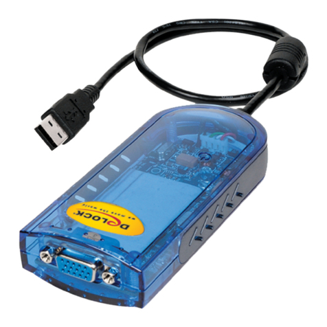
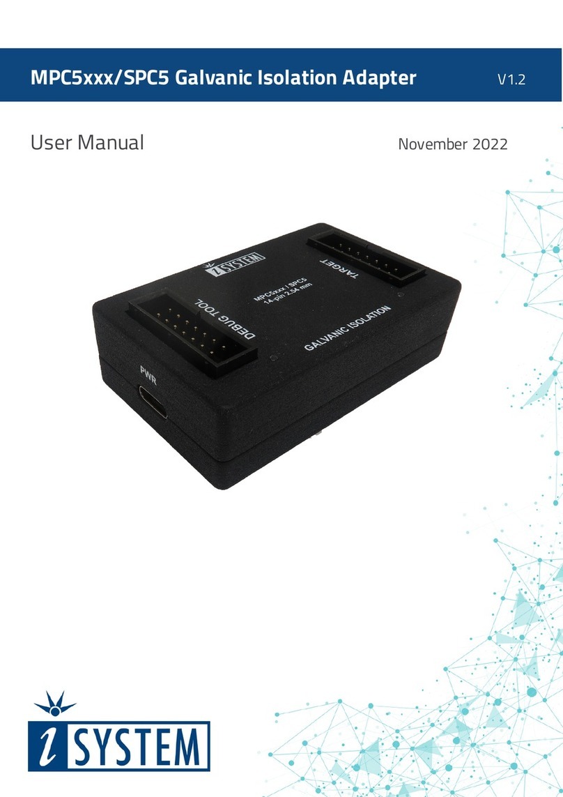
ECS IEEE 802.11b WLAN Mini USB Adapter User manual

USER’S GUIDE
VERSION 1.2
2004/04/14
Tested To Comply
With FCC Standards
FOR HOME OR OFFICE USE
IEEE 802.11b
WLAN Mini USB Adapter

© All rights reserved.
All trade names are registered trademarks of respective manufacturers listed.
This manual may not be copied in any media or form without the written consent of original maker.

TABLE OF CONTENTS
Welcome .................................................................. 1
Wireless LAN Basics ...................................................... 3
IP ADDRESS ................................................................ 4
Install Driver/Utility ..................................................... 5
Utility Configuration .................................................... 7
Windows XP Configuration .......................................... 8
SiS Advanced Configuration ........................................ 9
Technical Specifications ................................................ 12
Troubleshooting .......................................................... 13
Glossary ................................................................... 14

INFORMATION TO USER
Federal Communication Commission Interference Statement
This equipment has been tested and found to comply with the limits
for a Class B digital device, pursuant to Part 15 of the FCC Rules. These
limits are designed to provide reasonable protection against harmful
interference in a residential installation.
This equipment generates, uses and can radiate radio frequency
energy and, if not installed and used in accordance with the instructions,
may cause harmful interference to radio communications. However, there
is no guarantee that interference will not occur in a particular
installation. If this equipment does cause harmful interference to radio or
television reception, which can be determined by turning the equipment
off and on, the user is encouraged to try to correct the interference by
one of the following measures:
Reorient or relocate the receiving antenna.
Increase the separation between the equipment and receiver.
Connect the equipment into an outlet on a circuit different from
that to which the receiver is connected.
Consult the dealer or an experienced radio/TV technician for help.
This device complies with Part 15 of the FCC Rules. Operation is
subject to the following two conditions: (1) This device may not cause
harmful interference, and (2) this device must accept any interference
received, including interference that may cause undesired operation.
FCC Caution: Any changes or modifications not expressly approved
by the party responsible for compliance could void the user's authority to
operate this equipment.
IMPORTANT NOTE:
FCC Radiation Exposure Statement:
This equipment complies with FCC radiation exposure limits set
forth for an uncontrolled environment. This equipment should be
installed and operated with minimum distance 20cm between the
radiator & your body.
This transmitter must not be co-located or operating in conjunction
with any other antenna or transmitter.

This device is intended only for OEM integrators under the following
conditions:
1 ) The transmitter module may not be co-located with any other trans-
mitter or antenna.
As long as conduction above is met, further transmitter test will not
be required.
However, the OEM integrator is still responsible for testing their
end-product for any additional compliance requirements required with
this module installed (for example, digital device emissions, PC peripheral
requirements, etc.).
IMPORTANT NOTE: In the event that these conditions can not be met (for
example certain laptop configurations or co-location with another
transmitter), then the FCC authorization is no longer considered valid and
the FCC ID can not be used on the final product. In these circumstances,
the OEM integrator will be responsible for re-evaluating the end product
(including the transmitter) and obtaining a separate FCC authorization.
End Product Labeling
The final end product must be labeled in a visible area with the
following: “Contains TX FCC ID: PANWL1207”.
Manual Information That Must be Included
The OEM integrator has to be aware not to provide information to
the end user regarding how to install or remove this RF module in the
users manual of the end product which integrate this module.
The users manual for OEM integrators must include the following
information in a prominent location “ IMPORTANT NOTE: To comply with
FCC RF exposure compliance requirements. The antenna must not be co-
located or operating in conjunction with any other antenna or
transmitter.

REGULATORY INFORMATION
WLAN Mini USB Adapter must be installed and used in strict
accordance with the instructions. This device complies with the
following radio frequency and safety standards.
USA - Federal Communications Commission (FCC)
This device complies with Part 15 of FCC Rules. Operation is
subject to the following two conditions:
1. This device may not cause harmful interference.
2. This device must accept any interference that may cause undes-
ired operation.
Europe - R&TTE Directive
This device complies with the specifications listed below
• ETS 300-826 General EMC requirements for Radio equipment.
• ETS 300-328 Technical requirements for Radio equipment.
• EN60950 Safety Requirements for Radio equipment
The channel identifiers, channel center frequencies, and
regulatory domains of each 22-MHz-wide channel are shown in
following Table.
Channel Center
Identifier Frequency
(MHZ) North
America
12412X X X
22417X X X
32422X X X X
42427X X X X
52432X X X X
62437X X X X
72442X X X X
82447X X X X
92452X X X X
10 2457 X X X X X
11 2462 X X X X X
12 2467 X X X
13 2472 X X X
14 2484 X
Regulatory Domains
Japan ETSI Israel France Mexico

WELCOME
Thank you for your purchase of the WLAN Mini USB Adapter.
Featuring wireless technology, this wireless networking solution has
been designed for both large and small businesses, and it is scalable
so that you can easily add more users and new network features
depending on your business scale.
FEATURES
Support for Microsoft Windows 98SE, Me, 2000 and XP.
Operating distance of up to 300 meters in free space.
1Mbps, 2Mbps, 5.5Mbps, 11Mbps selectable Data Rate.
Support USB 1.1 interface.
64-bit or 128-bit WEP (Wired Equivalent Privacy).
2.400GHz ~ 2.4835GHz unlicensed ISM Frequency Band.
DSSS (Direct Sequence Spread Spectrum).
Modulation Method : DQPSK / DBPSK / CCK.
Easy operation and setting up.
SYSTEM REQUIREMENTS
Windows System : Windows 98SE, Me, 2000 or XP.
PCs must have a device driver installed. It allows you to commu-
nicate with WLAN Mini USB Adapter.
1

2
BEFORE YOU START
1. Confirm Box Contents
CONNECTING YOUR WLAN MINI USB ADAPTER TO PC
Quick Start Guide
Connect your WLAN USB dongle to your
PC.
Install driver.
GETTING TO KNOW WLAN MINI USB ADAPTER
LED
LED turns on when POWER is applied to the WLAN Mini USB Adapter.
LED is blinking when PC is sending data through WLAN Mini USB
Adapter.
WLAN Mini USB Adapter Driver CD

WIRELESS LAN BASICS
Wireless LAN network defined by IEEE 802.11b standard committee could
be configured as :
Ad Hoc wireless LAN, or
Infrastructure wireless LAN.
Ad Hoc network is a group of PCs installed with wireless LAN cards, this
group of PCs is called a BSS (Basic Service Set). PCs in this group can use
their wireless LAN cards to communicate with each other, but can not
connect to the Internet.
The most obvious difference between Infrastructure wireless network
and Ad Hoc wireless network is that the PCs in Infrastructure wireless
network can access the resource in the Internet through Access Point.
Depending on your requirement, you can easily set up your PC’s
network to be a “Ad Hoc” or “Infrastructure” wireless network. Gener-
ally speaking, if in your network, there is an Access Point in it, we recom-
mend you to set your network as an “Infrastructure”, so it can connect to
the Internet.
3
STA 1
STA 2
STA 3
Ad Hoc Wireless Network Infrastructure Wireless Network

IP ADDRESS
To use the WLAN Mini USB Adapter with a computing device, the WLAN
Mini USB Adapter must be equipped with an USB 1.1 or 2.0 Interface. All
drivers and supporting software for the WLAN Mini USB Adapter must be
installed and configured first.
Ask your system administrator for the following information, which you
may need to provide during driver installation :
Your Wireless Client Name.
Your Wireless SSID.
Your computer’s unique client name and workgroup name.
For your network account, your user name and password.
Your IP address, gateway address, and subnet mask if you’re not
using a DHCP server.
Any computer on a network is identified by a unique network address.
There are two methods to assign a network address to a computer on a
TCP/IP network :
Static IP addressing.
Dynamic IP addressing (DHCP).
In network with static IP addressing, the network administrator manually
assigns an IP address to each computer. Once a static IP address is
assigned, a computer uses the same IP address every time it reboots and
logs on to the network. You may manually change the IP address in the
Network Properties dialog box. Network using static IP address is easy to
set up and do not require additional network management software.
In network with dynamic IP addressing, a DHCP server in the network
dynamically assigns IP addresses to all clients every time they log on to
the network. Network using dynamic IP address requires setting up and
running a DHCP Server.
4

INSTALL DRIVER / UTILITY
Step 1 :
Please put the Driver CD into the
CD drive of your PC, Windows XP/
2000 will look from the CD content
and automatically run the installa-
tion program (the so-called
autorun). The Welcome dialog will
pop up.
Please click Next.
Step 2 :
Select components :
Wireless LAN Driver.
Wireless LAN Utility.
Click Next.
Step 3 :
Start copying.
5

Step 4 :
Click Finish to complete the installation.
Step 5 :
After you finish the installation of the device driver, you can then insert
the WLAN USB Mini Adapter to your PC. At this moment, Windows system
will detect it automatically, and an icon will be displayed on the
lower right hand corner of your screen.
After installing driver and utility on your system, let us start configuring
your wireless LAN card.
6

UTILITY CONFIGURATION
There are two different ways to configure your WLAN Mini USB Adapter on
your Windows system, both of them are working similarly, you can choose
either one of them to meet your need.
Method 1 - Windows XP Configuration
Step 1 : After installing driver and utility on your system, let us start to
configure your wireless LAN card. At first, from the lower right hand
corner of your screen, right click on the Network Connection.
Step 2 : Click on the View Available Wireless Networks.
A Wireless Network dialog will pop
up. If there is any Access Point in
the neighborhood and which RF
transmitting/receiving power
covers the range of your WLAN
Mini USB Adapter, then the SSID of
this Access Point will be displayed
in the list of “Available networks”.
Select one and click the Connect
button. (You can select the closest
Access Point in the neighborhood,
which can guarantee the best
connectivity.)
7

Method 2 - SiS Advanced Configuration
The second configuration utility comes from chip vendor - SiS. A SiS
Baseband/MAC WLAN chip is used in this WLAN USB Mini Adapter.
Step 1 : Plug in the WLAN Mini USB Adapter to your PC, and you will see a
SiS WLAN icon appears on your system tray.
Step 2 : Double-click on the icon, a “SiS162 USB Wireless LAN
Adapter” dialog box will appear.
The dialog box contains several fields where parameters of the driver can
be viewed or changed. Changes of the parameters in this panel can be
applied to the driver without any need to restart your PC.
1 . The NetStatus tab shows :
Link Status.
Network mode.
SSID.
Channel.
Tx Rate.
You can go to NetStatus tab to
change your Ad hoc or Infrastruc-
ture network mode, enable or
disable Data Encryption, set your
SSID, configure a Channel number
for RF transmission or fix Tx Rate
on a specified speed.
8

2. Click on the Site Scan tab.
Click Re-Fresh button, all Access
Points and Ad-hoc devices within
the detectable range will be found
and their relative information will
be displayed in the list. You then
can assign an Access Point or Ad-
hoc devices with which you want
your WLAN Mini USB Adapter to
connect. You can establish a
connection or a link by just
double-clicking on the SSID from
the list.
If you check “Use Windows XP to configure my wireless network
settings”, then you have to use Windows XP configuration utility men-
tioned in Method 1 to configure the Wireless link function.
3 . Statistics tab allows you to
check the Link State, Signal
Strength, and the Transmitting/
Receiving Statistics data. If you
check the box - Turn Radio OFF,
then any radio activity will be
turned off.
9

4 . If there are several wireless
networks co-exist in a building,
and you do not want any company
message be shared, at this
moment, you must consider data
encryption.
The setting of security KEY shall
be done on both of your WLAN
Mini USB Adpater and Access
Point. If any one of them does not
match, then the connection will
fail.
Select the Encryption tab.
Set the Data Encryption to WEP
to enable the function. WEP
encrypts each data frame trans-
mitted from the radio using one of the Keys entered in this panel. Each
key must consist of only hexdecimal digits, it means that only digit 0-9
and letters A-F are valid. Wrong input key will not enable WEP function.
5 . The Info tab shows the Driver
version including the detail of
Configuration Utility and NIC
firmware version. User must use
this version number when report-
ing problems for future technical
support.
10

6 . The Profile tab allows you to
save the information associated
with a specific setting, so you can
quickly and easily connect to your
network when you are in its
neighborhood. The Profile page
allows you to create a new
profile, delete an old profile or
edit your existing profile.
11

Standard IEEE802.11b
Frequency Band 2.4GHz ~ 2.4835GHz unlicensed ISM band
Spread Spectrum DSSS (Direct Sequence Spread Spectrum)
Modulation method DQPSK / DBPSK / CCK
Data Rate 1Mbps, 2Mbps, 5.5Mbps, 11Mbps
Ad hoc
Infrastructure (Access Points is needed)
Transmitter Power 17 dBm
Receive Sensitivity Operating at 11Mbps: >8% PER @ –86dBm
Operating Range 100 - 400m, depending on surrounding environment
Antenna On board chip antenna
Transmit : < 350mA.
Receive : < 260mA.
64-bit or 128-bit WEP (Wired Equivalent Privacy) /WPA
TKIP (Temporal Key Integrity Protocol)
I/O Interface USB 2.0
LED Blue LED indicator
Operating System Windows 98SE, Me, 2000, XP
Management Windows-based Utility
FCC part 15B/C for North America.
CE for Europe.
Operating Temperature 0 ~ 55℃
Storage Temperature -20 ~ 70℃
Humidity 5 ~ 90% (non-condensing)
Size 58(L) x 23(W) x 10(H) mm
Operation Mode
Power Consumption
Regulation
Security
TECHNICAL SPECIFICATIONS
12

TROUBLESHOOTING
Symptom :
The LED is off.
Possible Remedy :
Make sure the PC Card is inserted properly. Otherwise contact your
vendor.
Symptom :
The LED is always on not blinking.
Possible Remedy :
Make sure that you have installed the driver from attached CD. Otherwise
contact your vendor.
Symptom :
The LED is blinking but the PC Card icon does not appear in your icon tray.
Possible Remedy :
Make sure that you have installed the Utility from the attached CD.
Symptom :
The PC Card is linking, but can’t share files with others.
Possible Remedy :
Make sure the file and printer sharing function is enabled. You could
enable the function by checking the icon of My Computer -> Control
Panel -> Network -> file and printer sharing -> I want to be able to give
others to access to my files.
Symptom :
Slow or erratic performance.
Possible Remedy :
Try changing the channel of the communicating group or moving your
device closer to the communicating device.
Symptom :
Can’t find the utility icon in the task bar when plugged in the WLAN card.
Possible Remedy :
You could enable the function by clicking the icon of start -> All Programs
-> Wireless LAN Utility -> SiSCFG
13

GLOSSARY
IEEE 802.11 Standard
The IEEE 802.11 Wireless LAN standards subcommittee, which is formulat-
ing a standard for the industry.
Access Point
An internetworking device that seamlessly connects wired and wireless
networks together.
Ad Hoc
An Ad Hoc wireless LAN is a group of computers, each with a WLAN
adapter, connected as an independent wireless LAN. Ad Hoc wireless LAN
is applicable at a departmental scale for a branch or SOHO operation.
BSSID
A specific Ad Hoc LAN is called a Basic Service Set (BSS). Computers in a
BSS must be configured with the same BSSID.
DHCP
Dynamic Host Configuration Protocol - a method in which IP addresses are
assigned by server dynamically to clients on the network. DHCP is used for
Dynamic IP Addressing and requires a dedicated DHCP server on the
network.
Direct Sequence Spread Spectrum
This is the method the wireless cards use to transmit data over the fre-
quency spectrum. The other method is frequency hopping. Direct se-
quence spreads the data over one frequency range (channel) while fre-
quency hopping jumps from one narrow frequency band to another many
times per second.
ESSID
An Infrastructure configuration could also support roaming capability for
mobile workers. More than one BSS can be configured as an Extended
Service Set (ESS). Users within an ESS could roam freely between BSSs
while served as a continuous connection to the network wireless stations
and Access Points within an ESS must be configured with the same ESSID
and the same radio channel.
14
Table of contents
Other ECS Adapter manuals
