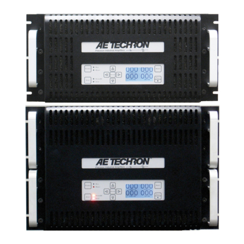
Ectron 560H User manual

INSTRUCTION MANUAL
MODEL 560H
AMPLIFIER
The information in this manual is proprietary and may not be reproduced without written
permission from this company.
LIFE-SUPPO T POLICY: Ectron products are not authorized for use in life-support devices or
systems without the express, written approval of the President of Ectron Corporation.
Copyright 2018 Ectron Corporation
Ectron Corporation 8159 Engineer oad
All ights eserved San Diego, CA 92111-1907
858-278-0600
800-732-8159
Fax: 858-278-0372
E-mail: [email protected]
Web site: www.ectron.com

WARRANTY
GENERAL
All Ectron instruments are warranted against defects in material and workmanship for one year from the
date of shipment to the original purchaser. Ectron agrees to repair or replace any assembly or components
(except expendable items such as fuses, lamps, batteries, etc.) found to be defective during this period.
Ectron’s obligation under this warranty is limited solely to repairing or replacing, at its option, an
instrument that in Ectron’s sole opinion proves to be defective within the scope of the warranty when
returned to the factory or to an authorized service center. Transportation to the factory or service center is
to be prepaid by the purchaser. Shipment should not be made without the prior authorization of Ectron.
This warranty does not apply to products repaired or altered by persons not authorized by Ectron, or not
in accordance with instructions furnished by Ectron. If the instrument is defective as a result of misuse,
improper repair, alteration, neglect, or abnormal conditions of operation repairs will be billed at Ectron’s
normal rates. Ectron assumes no liability for secondary charges of consequential damages as a result of an
alleged breach of this warranty; and in any event, Ectron’s liability for breach of warranty under any
contract or otherwise shall not exceed the purchase price of the specific instrument shipped and against
which a claim is made. This warranty is in lieu of all other warranties, expressed or implied; and no
representative or person is authorized to represent or assume for Ectron any liability in connections with
the sale of our products other than is set forth herein.
PROCEDURE FOR SERVICE
If a fault develops, notify Ectron or its local representative, giving full details of the difficulty. Include the
model and serial numbers. On receipt of this information, a service date or shipping instructions will be
furnished. If shipment is indicated, forward the instrument, freight prepaid, to the factory or to the
authorized service center indicated in the instructions.
DAMAGE IN TRANSIT
Instruments should be tested upon receipt. If there is any damage, a claim should be filed with the carrier.
A full report of the damage should be obtained by the claim agent, and that report should be forwarded to
Ectron. Ectron will advise the disposition to be made of the equipment and arrange for repair or
replacement. Please include model and serial numbers in all correspondence.
Ectron Corporation
8159 Engineer oad
San Diego, CA 92111-1907
Sales Department
800-732-8159, ext. 675

TABLE OF CONTENTS
Section I Description
General 1-1
Model 560H Features 1-1
Available Amplifier Options 1-1
Summary of Controls Terminals and
Indicators 1-1
Front Panel 1-1
Internal 1-1
Enclosures 1-1
E513-2A 1-1
E513-6A 1-2
513-16 1-2
Available Accessories 1-2
Tables
1-1, Summary of Enclosures 1-2
1-2, Enclosure Connector Pin Designations 1-3
Section II Specifications
Input Characteristics 2-1
Configuration 2-1
Impedance 2-1
Source Current, Stability 2-1
Source Current, Temperature 2-1
Maximum Overload 2-1
Guard Impedance 2-1
Common-mode Voltage 2-1
Zero 2-1
Stability 2-1
Temperature Coefficient 2-1
TO ange 2-1
TI ange 2-1
Common-mode Rejection 2-1
Dc to 60 Hz with 350 Unbalance 2-1
Dynamic Response 2-1
Bandwidth (within 3 dB) 2-1
Slew ate 2-1
Settling Time 2-1
Overload ecovery 2-1
Filtered output 2-1
Noise 2-1
MS 2-1
Peak 2-2
Gain (Vernier Out) 2-2
Steps 2-2
Vernier 2-2
Accuracy 2-2
Stability 2-2
Input Divider 2-2
Linearity 2-2
Output 2-2
Voltage 2-2
Short-circuit Protection 2-2
Impedance 2-2
Capacitive Loading (No Instability) 2-2
Current, dc or ac rms 2-2
Power Dimensions and Environment 2-2
Amplifier 2-2
Options 2-2
Operating Environment 2-2
Storage Temperature 2-2
Dimensions 2-2
Section III Unpacking and Inspection
General 3-1
Section IV Initial Checkout
General 4-1
Input Connections 4-1
Output Connections 4-1
Test Equipment Required 4-2
Function Generator 4-2
Precision Voltage Divider 4-2
Differential Oscilloscope 4-2
esistors 4-2
Procedure 4-2
Gain 4-2
Frequency esponse 4-3
Filtered Output (Options L, M, and N) 4-3
Figure
4-1, Initial Amplifier Test Setup 4-2
Table
4-1, Card-edge Connector J1 Pin
Assignments 4-1
Section V Applications
Safety 5-1
Model 560H Operating Controls 5-1
Gain Controls 5-1
Zero Controls 5-1
i

Table of Contents Model 560H
Zero Indicators, Output Monitor Jacks 5-1
Signal Wiring 5-1
Common-mode Effects 5-2
Common-mode Voltage 5-2
Enclosures 5-2
Model 513-16 5-2
Model E513-6A Enclosure 5-2
Model E513-2A Enclosure 5-3
Model 516 Series Enclosure 5-3
Other Application Notes 5-3
Loads 5-3
Output Grounding Problems 5-3
Figure
5-1, Jumper emoval for a Model 560H in an
E516 Series Enclosure 5-3
Section VI Theory of Operation
General Circuit Description 6-1
Gain esistors 6-1
Detailed Circuit Description 6-1
Amplifier 6-1
Filter Amplifier 6-2
High-current Amplifier 6-2
Zero Detector 6-3
R513-16 Enclosure 6-3
E513-6A Enclosure 6-3
E513-2A Enclosure 6-3
Figure
6-1, Model 560H Simplified Amplifier
Schematic 6-2
Table
6-1, Gain combinations to provide the
indicated gain step 6-1
Section VII Calibration and Maintenance
General 7-1
Test Equipment Required 7-1
Power Supply 7-1
Precision Voltage Divider 7-1
Differential Oscilloscope 7-1
Switches 7-1
esistors 7-1
Null Detector 7-1
Function Generator 7-1
ms Meter 7-1
Mating Connector 7-1
DMM 7-1
Preliminary Adjustments 7-1
Zero Adjustments (Figure 7-1) 7-1
TO 7-1
TO (Options K, L, M, and N) 7-1
TI 7-2
Zero Detector 7-2
Source-current Adjustments 7-2
Common-mode-rejection Adjustment 7-2
Gain Calibration 7-3
Test Procedures 7-3
Gain Accuracy 7-3
Linearity 7-4
Input Impedance 7-4
Output Impedance 7-4
Frequency esponse 7-4
Noise 7-5
Bench Testing 7-5
Figures
7-1, Basic Test Setup 7-2
7-2, Test Setup for Frequency esponse 7-3
7-3, Test Setup for Noise and Common-mode
ejection 7-4
Section VIII Parts List
Abbreviations 8-1
Model 560H Amplifier 8-2
Model 560H Filter Assembly 8-3
Model 560H High-current Assembly 8-3
Model E513-2A Enclosure 8-4
Model E513-6A 8-4
Model R513-16 Enclosure 8-5
Accessories For All Enclosures 8-5
Schematics
Model E513-2A Power Supply 513-603
Model E513-2A Enclosure 513-604
Model E513-6A Enclosure 513-613
Model 513-16 Enclosure 513-622
Model 560H Filter Assembly 550-602
Model 560H Amplifier 560-602
Model 560H High-current Output
Assembly 563-603
ii

SECTION I
1DESCRIPTION
GENERAL
The Model 560H amplifier is a wideband, true
differential dc instrumentation amplifier. It offers a
high level of performance at a moderate cost for a
wide variety of applications. The compact design
features outstanding linearity, gain stability, and
input impedance. Excellent overall accuracy is
assured due to direct coupling and very high loop
gains. The internal circuitry uses discrete compo-
nents and integrated circuits to provide “state of
the art” performance while keeping the cost and
complexity to a minimum. The low power con-
sumption reduces warm-up time and component
aging due to internally-generated temperature rise.
All components are mounted on a single circuit
card. Certain options are included on smaller
circuit cards, which are plugged into the amplifier
circuit card. The output of the basic amplifier is
±10 V at 10 mA. Filtered outputs and high-current
capability are available options.
MODEL 560H FEATURES
A switch-selectable 100:1 input divider.
A switchable TO-zero range control with
ranges of 0.1 V, 1 V, and 10 V.
Front-panel output-monitor jacks.
Optional filtered output of 10 Hz, 100 Hz,
1 kHz, 10 kHz, and wideband front-panel
switch-selectable positions.
Optional 100 mA peak (50 mA rms or dc)
output on either wideband or filtered output.
AVAILABLE AMPLIFIER OPTIONS
Option J
Wideband output of ±10 V at 10 mA.
Option K
Wideband output of ±10 V at 100 mA rms or
dc output. (See Footnote 1 on Page 2-2.)
Option L
Wideband output of ±10 V at 10 mA and a
selectable filtered output of ±10 V at 10 mA.
Option M
Wideband output of ±10 V at 100 mA rms or
dc and a selectable filtered output of ±10 V at
10 mA. (See Footnote 1 on Page 2-2.)
Option N
Wideband output of ±10 V at 10 mA and a
selectable, filtered output of ±10 V at 100 mA
rms or dc. (See Footnote 1 on Page 2-2.)
SUMMARY OF CONTROLS TERMINALS
AND INDICATORS
FRONT PANEL
Output monitor jacks (blue and black).
Output polarity-indicating LED’s.
otary gain switch.
Vernier gain-control potentiometer.
Vernier gain in-out toggle switch.
otary output filter switch (Options L, M, and
N only).
TI-zero potentiometer.
INTERNAL
Three-position TO-zero range slide switch.
100:1 input-divider slide switch.
Sensitivity-control potentiometer for the
amplifier output-polarity indicator LED’s
(zero detector).
ENCLOSURES
Enclosures are supplied with a three-wire power
cord and mating connectors for the amplifier inputs
and outputs unless stated otherwise.
E513-2A
This enclosure with integral power supplies
will accept up to two Model 560H units and is
intended for bench or portable use. All connec-
tions except input power are made to barrier
strips on the rear of the enclosure. A rear-panel
switch is used to inhibit the operation of the
zero-detector LED’s in all amplifiers. The
1-1

Description Model 560H
enclosure is 89 mm (3.5) high, 216 mm (8.5)
wide, and 229 mm (9) deep.
E513-6A
This enclosure with integral power supplies is
also intended for bench or portable use. It will
accept up to six Model 560H units. A front-
panel switch is used to inhibit the operation of
the zero-detector LED’s in all amplifiers. The
supplied input mating connectors are
PT06A-10-6P(S ) (Ectron P/N 1-310506-0),
and the amplifier wideband- and filter-output
(Options L, M, and N) connectors are isolated
BNC (mates not normally supplied). The
enclosure is 152 mm (6) high, 229 mm (9)
wide, and 305 mm (12) deep.
R513-16
This standard 483 mm (19) rack-mount enclo-
sure with integral power supplies will accept
up to sixteen Model 560H units.
The enclosure includes a front-panel switch to
inhibit the operation of the ZE O DETEC-
TO LED’s in all amplifiers.
Three null indicators are used for remote
operation to provide isolation and interface
flexibility. The couplers are bypassed for local
operation using the front-panel mode switch.
Two isolated power supplies are used in each
enclosure. One provides the ±16 V necessary
for amplifier operation, and the other provides
15.9 V for the excitation supplies and 25 V
for remote operation (not used with the Model
560H).
The supplied input mating connectors are
PT06A-10P-6P(S ) (Ectron P/N 1-310506-0),
the outputs are BNC (mates not normally
supplied), and the remote control connector is
PT06A-128P(S ) (Ectron P/N 1-310408-0).
The enclosure is 133 mm (5.25) high,
483 mm (19) wide, and 457 mm (18) deep.
AVAILABLE ACCESSORIES
ECTRON PART NUMBER
Extender Board: 560-501-01
Enclosure Filler Panels
One-channel: 516-503-40
Four-channel: 516-503-55
Table 1-1: Summary of Enclosures
E513-2A E513-6A R513-16
Channels 2 6 16
Heigh 89 mm (3.5) 152 mm (6) 133 mm (5.25)
Wid h 216 mm (8.5) 229 mm (9) 483 mm (19)
Dep h 229 mm (9.0) 305 mm (12) 457 mm (18)
Line Vol age 120/240 V ac 120/240 V ac 120/240 V ac
Ampl P/S ±16 V dc ±16 V dc ±16 V dc
Exci P/S +15.9 V dc +15.9 V dc +15.9 V dc
Inpu Ma es Barrier Strip PT06 -10-6P(SR)
(1-310506-0)
PT06 -10-6P(SR)
(1-310506-0)
Ou pu Ma es Barrier Strip BNC (Not supplied) BNC (Not supplied)
Remo e Ma e PT06 -12-8P(SR)
(1-310408-0)
Dc-power Ma e PT06 -12-3S(SR)
(1-310103-1)
1-2

Model 560H Description
Table 1-2: Enclosure Connec or Pin Designa ions
E513-2A E513-6A R513-16
Noninver ing Inpu 2 B B
Inver ing Inpu 3 C C
Shield 5 E E
Bridge Comple ion 6 F F
+ Exci a ion 1
Exci a ion 4 D D
Fil ered Ou pu High 8 * *
Fil ered Ou pu Low 7 * *
Wideband Ou pu High 10 * *
Wideband Ou pu Low 9 * *
* Models E513-6A and 513-16 enclosures use BNC output connectors.
1-3

Description Model 560H
1-4

SECTION II
2SPECIFICATIONS
Unless otherwise noted, all specifications apply at
25°C after thirty minutes warm-up with 0 to
1 k source resistance in any unbalance. TI is
referred-to-input. TO is referred-to-output. The
specifications are the maximum from nominal
allowed unless stated otherwise.
INPUT CHARACTERISTICS
CONFIGURATION
Differential, direct coupled. May be used in-
verting, noninverting, or single-ended. An
input ground return is not required except for
noise pickup problems.
IMPEDANCE
50 M nominal (1 M with 100:1 divider
switched in) in parallel with 300 pF.
SOURCE CURRENT STABILITY
±2 nA for 200 hours.
SOURCE CURRENT TEMPERATURE
±0.5 nA/°C.
MAXIMUM OVERLOAD
±20 V dc or peak ac common or normal mode
(±300 V dc or peak ac when 100:1 input
divider is in).
GUARD IMPEDANCE
10 M to output common nominal.
COMMON-MODE VOLTAGE
±10 V dc or peak ac operating (±300 V dc or
peak ac when 100:1 input divider is in).
ZERO
STABILITY
±4 µV TI and ±0.35 mV TO for 200 hours.
TEMPERATURE COEFFICIENT
±1 µV/°C TI and ±0.35 mV/°C TO.
RTO RANGE
Three switch-selectable ranges of ±0.1 V,
±1 V, and ±10 V.
RTI RANGE
±350 µV nominal.
COMMON-MODE REJECTION
DC TO 60 HZ WITH 350 UNBALANCE
>50 dB gain in dB.
DYNAMIC RESPONSE
BANDWIDTH (WITHIN 3 dB)
Small Signal (1 V rms): dc to 200 kHz.
Full signal (20 V p-p): gain of 1, dc to 20 kHz;
gain of 2, dc to 50 kHz; gains of 5 to 1000, dc
to 100 kHz.
SLEW RATE
Gain of 1, 1.2 V/µs; gain of 2, 2.4 V/µs; gains
of 5 to 1000, 6.3 V/µs.
SETTLING TIME
10 µs to within ±0.1% of final value.
OVERLOAD RECOVERY
50 µs to within ±0.1% of final value from a
500% overload.
FILTERED OUTPUT
3 dB ±1 dB at settings of 10 Hz, 100 Hz,
1 kHz, 10 kHz, and wideband position.
NOISE
RMS
From 0.1 Hz to 200 kHz: 4 µV TI 0.5 mV
TO.
From 0.1 Hz to 1 MHz MS: 4 µV TI
1.0 mV TO.
2-1

Specifications Model 560H
PEAK
From 0.1 Hz to 10 Hz: 0.75 µV TI 50 µV
TO.
GAIN (VERNIER OUT)
STEPS
1, 2, 5, 10, 20, 50, 100, 200, 500, and 1000.
(0.01, 0.02, 0.05, 0.1, 0.2, 0.5, 1, 2, 5, and 10
with 100:1 input divider switched in.)
VERNIER
1 to >2.5 times the step gain.
ACCURACY
Better than ±0.1%.
STABILITY
Time
±0.01%, 90 days.
Temperature
±0.005%/°C.
INPUT DIVIDER
100:1. (Adds 0.1% error to overall gain
accuracy.)
LINEARITY
Within ±0.005% of the best straight line
through zero.
OUTPUT
VOLTAGE
±10 V dc or peak ac.
SHORT-CIRCUIT PROTECTION
No damage with sustained short circuit on
either or both outputs.
IMPEDANCE
0.1 .
CAPACITIVE LOADING (NO INSTABILITY)
Wideband output, up to 0.01 µF; filtered
output, up to 0.1 µF.
CURRENT DC OR AC RMS
Current
Option Wideband Filtered
J 10 mA None
K 100 mA1None
L 10 mA 10 mA
M 100 mA110 mA
N 10 mA 100 mA1
POWER DIMENSIONS AND
ENVIRONMENT
AMPLIFIER
±16 V to ±18 V, 18 mA output load.
OPTIONS
K Adds 16 mA load.
L Adds 5 mA load.
M Adds 21 mA load.
N Adds 21 mA load.
OPERATING ENVIRONMENT
0°C to 50°C, 90% H.
STORAGE TEMPERATURE
25°C to 71°C.
DIMENSIONS
133 mm (5.25) high, 23 mm (0.9) wide, and
203 mm (8) long.
1 100 mA rms or dc except when limited by the enclosure
power supply. With all amplifiers equally loaded in an 513-
16 enclosure, each amplifier can supply 80 mA; in an E513-
6A, 100 mA; and in the E513-2A, 70 mA.
2-2

SECTION III
3UNPACKING AND INSPECTION
GENERAL
This instrument was thoroughly tested and inspected prior to shipment, and unless damaged in transit, it
should be ready for use when received.
The shipping carton should be examined for signs of damage before unpacking. If external damage is
present, notify the carrier before proceeding.
emove the contents of the carton and carefully examine all units for any evidence of damage due to
excessive shock, vibration, water, etc. If there is evidence of physical damage, notify the carrier.
Account for all items on the packing list, including mating connectors and instruction manuals. If the
inventory of equipment does not correspond with the packing slip, notify Ectron Corporation.
If all is satisfactory, proceed with Section IV, INITIAL CHECKOUT.
3-1

Unpacking and Inspection Model 560H
3-2

SECTION IV
4INITIAL CHECKOUT
GENERAL
The simple tests described in this section are
generally sufficient to check the instrument on
receipt. The purpose of these tests is only to esta-
blish that the instrument is in operating condition.
This procedure is not a substitute for the specifica-
tion tests in Section VII, which the user may want
to perform before placing the unit in service.
Table 4-1: Card-edge Connec or J1 Pin
Assignmen s
1Filtered output high
2Zero-detect control
316 V Unregulated
4Wideband output high
5+16 V Unregulated
KEY
6Output and power low
7Output and power low
816 V Regulated
9Not used
10 +16 V Regulated
11 Not used
12 Not used
SLOT To reduce capacitance between
Pins 12 and 13.
13 Inverting input
14 Noninverting input
15 Shield
16 Not used
17 Not used
18 Not used
WARNING
When using an enclosure make sure that its
chassis is connected to earth ground preferably
through third-wire ground.
An Ectron Model 560H amplifier can be tested in a
513 Series or 516 Series enclosure or on the bench.
If an Ectron 516 Series enclosure is used, please
refer to Note 2 on Drawing 560-602 and Figure 5-1
concerning the removal of Jumpers EE and FF.
CAUTION
Failure to remove Jumpers EE and FF will re-
sult in damage to the internal power supplies of
the 516 series enclosure.
Table 4-1 shows the card-edge connector J1 pin
assignments for the Model 560H if it is to be
bench-tested. The mating connector is a Cinch
50-18-A-20 (Ectron P/N 1-314018-0) with a polar-
izing key Cinch 50-PK-2 (Ectron P/N 1-319201-0)
installed between Pins 5 and 6.
CAUTION
Ensure that connections to the amplifier are
correct before applying power or signal volt-
ages. Refer to Table 4-1 for correct pin assign-
ments. Note that all pins are connected to their
complements by plated-through holes.
INPUT CONNECTIONS
The input is applied to J1, Pins 13 () and 14 ().
In most installations the input leads are guarded
electrostatically by an isolated and insulated shield
which is connected to guard J1, Pin 15.
CAUTION
Be sure that the signal source connected to the
amplifier input does not exceed 20 V dc or peak
ac with respect to output and power low or
serious damage may occur.
OUTPUT CONNECTIONS
The wideband output is available on J1, Pins 4
(high) and 7 (common), and the filtered output on
J1, Pin 1 (high) and J1, Pin 6 (common). For these
tests either or both common pins should be
connected to the low side of all test equipment and
connected to power line ground. Tests on both
outputs can then be conducted by switching the
oscilloscope between J1, Pin 4 and Pin 1.
4-1

Initial Checkout Model 560H
TEST EQUIPMENT REQUIRED
FUNCTION GENERATOR
Wavetek Model 180 or equivalent.
PRECISION VOLTAGE DIVIDER
ESI V622A or equivalent. The divider must
have an input resistance of 10 k or more.
DIFFERENTIAL OSCILLOSCOPE
Tektronix 5110 main frame, with 5B10N time
base and 5A21 differential amplifier or equiva-
lent. Be sure the oscilloscope has been
adjusted for common-mode rejection accord-
ing to the manufacturer’s instructions as differ-
ential measurements are used in the procedure
that follows.
RESISTORS (CARBON FILM OR
COMPOSITION ¼ W)
One 10 k, and one 100 .
PROCEDURE
GAIN (REFER TO FIGURE 4-1)
Although the Model 560H is designed as a
differential amplifier, it may also be operated in a
single-ended mode. Gain and frequency response
tests are made in the single-ended, noninverting
mode.
1. Connect the commons of the oscillator,
voltage divider, oscilloscope, and the
amplifier under test Pins 7 and 13 to a single
point. All measurements will be made in
reference to this point.
2. Connect the single point to power line
ground.
3. Connect the oscillator output to the input of
the voltage divider.
4. Connect the output of the divider to the
noninverting input J1, Pin 14. The other input
J1, Pin 13 is connected to the single-point
common.
5. Connect the amplifier wideband output J1,
Pin 4 to the oscilloscope input. The
oscilloscope must be direct coupled and
adjusted to zero. The wideband output can be
observed between the blue and black front-
panel jacks on the Model 560H.
6. Adjust the output of the oscillator to
minimum.
7. Apply power to the amplifier. The trace on
the oscilloscope should show that the output
of the amplifier is within a few millivolts of
zero.
8. Position the vernier switch to out.
9. Position the gain switch to 1000.
10. Adjust the output of the oscillator to 10 V p-p
at 100 Hz.
11. Adjust the voltage divider to the reciprocal
(0.001) of the gain setting. The oscilloscope
should show approximately 10 V p-p.
12. Switch in the 100:1 input divider S5.
13. Adjust the voltage divider to the reciprocal
(0.1, or 0.001 times 100) of the new gain
setting (10, or 1000 divided by 100). The
oscilloscope should again display
approximately 10 V p-p.
4-2
Figure 4-1: Ini ial Amplifier Tes Se up

Model 560H Initial Checkout
14. Switch out the 100:1 input divider.
FREQUENCY RESPONSE (REFER TO
FIGURE 7-2)
1. Fashion a voltage divider with a ratio of
approximately 100:1 using the 10 k and
100 carbon resistors. Do not use a
commercial decade voltage divider as most
have limited frequency response.
2. Change the gain of the amplifier under test to
100.
3. Adjust the function generator to a 1 V p-p
sine wave at 100 Hz.
4. Measure and record the output of the
amplifier (1 V p-p).
5. Change the function generator’s frequency to
200 kHz. eadjust the amplitude of the
generator to 1 V p-p if necessary.
6. Measure the output of the amplifier. It should
be 1 V p-p ±30%.
FILTERED OUTPUT (OPTIONS L M
AND N)
The frequency response on each bandwidth
setting can be checked at the filtered output J1,
Pin 1. The response should be 3 dB ±1 dB at
the appropriate cut-off frequency decreasing
by 12 dB/octave at higher frequencies. (The
rolloff in the wideband position will be
3 dB/octave.)
4-3

Initial Checkout Model 560H
4-4

SECTION V
5APPLICATIONS
SAFETY
When using the Model 560H in an ac-powered
enclosure, ensure that the chassis is connected to
“earth” ground. This is normally accomplished
using the ac-line cord that accompanies the
enclosure.
MODEL 560H OPERATING CONTROLS
A number of controls are available on the front
panel of all Model 560H amplifiers. In addition,
two operating controls, TO offset and the 100:1
divider, are located on the circuit card. The switch-
able filter control is available only on those ampli-
fiers having Option L, M, or N.
GAIN CONTROLS
The step-gain control provides an accuracy of
±0.1% of the indicated step-gain position when the
VE Nier IN/OUT switch is OUT. The VE Nier
control increases the fixed gain step by more than
2.5 times, so the overall gain range without divider
is from 1 to more than 2500.
The 100:1 gain divider IN/OUT switch is located
at the connector end of the main circuit card of the
Model 560H. This control reduces the front-panel
gain settings by a factor of 100 thereby affording a
total gain range from 0.01 to more than 2500. With
the divider in use, input impedance drops from the
nominal 50 M to 1 M.
ZERO CONTROLS
The 560H has two controls that affect amplifier
zero: TI zero and TO zero with its associated
three-step range switch. ( TI stands for referred-
to-input and TO stands for referred-to-output.)
The TO-zero potentiometer, located on the front
panel, produces an offset at the output of the
amplifier that has a range determined by a three-
position switch located at the connector end of the
circuit card. The range switch is labeled with its
full-scale ranges of ±0.1 V, ±1 V, and ±10 V. That
is, the front-panel TO-zero potentiometer can
offset the output by ±0.1 V, ±1 V, or ±10 V. Note
that the resolution of the TO-zero control
diminishes as range increases.
The TI-zero potentiometer, also located on the
front panel, affects the input zero of the amplifier
ahead of the gain-multiplying circuits. Thus the
effect at the output of the amplifier of the TI-zero
control increases with increasing gain (whereas the
TO-zero control setting is independent of gain).
For example, if the amplifier’s input is shorted and
the TI-zero control is set such that there is an
input offset of 20 µV, assuming the TO-zero
control is set for zero output at low gain; as gain
increases, output zero will become increasingly
further from zero by an amount equal to the gain
times the 20 µV offset. Although amplifier opera-
tion will be normal with the zero controls set off
zero, the proper method of setting zero controls is
to set TO zero at low gain and TI zero at high
gain. By repeating this procedure a few times the
output will remain at zero when gain is varied
throughout its total range.
ZERO INDICATORS OUTPUT MONITOR
JACKS
The amplifier’s output signal is available on the
front-panel monitor jacks labeled HI and LO.
These jacks can be connected to a meter to deter-
mine the output level or to set zeros. Also located
on the front panel are two LED indicators that
show the output condition of the amplifier. One
LED, labeled , is energized when the offset is
plus and the other LED, labeled , is energized for
minus. When both LED’s are extinguished, the
amplifier output is within approximately 2 mV of
zero. (The range is from 2 mV to 20 mV
depending on the setting of 84.) Noise will cause
both LED’s to turn on and if it is sufficient may
mask a null condition.
SIGNAL WIRING
Two-conductor, twisted-pair shielded cable is rec-
ommended for wiring to the inputs of the ampli-
fier. A dc return path from input to output low is
not required unless it is needed for noise reduction.
5-1

Applications Model 560H
The wire should be copper to minimize thermal
effects, and the shielding should be 100% coverage
to minimize degradation in common-mode rejec-
tion. The shield should be continued as close as
possible to the connector termination. The input
signal leads should neither be routed near conduc-
tors which carry high ac currents nor be near
equipment producing magnetic fields.
Output wiring should be two-conductor twisted
pair with or without shield. If shielded, the shield
should be tied to output common at the amplifier,
not the load. The pin assignments for the card-edge
connector are listed in Table 4-1.
COMMON-MODE EFFECTS
The common-mode potential of an input signal is
that floating potential common to both input leads
with respect to output common. For example, if the
amplifier is measuring the voltage drop across a
shunt located in the 5 V lead of a power supply,
the common-mode voltage is the 5 V supply
voltage and the desired signal is the millivolt drop
across the shunt. (This assumes that the common
of the 5 V supply is tied to output common of the
amplifier.) The common-mode rejection of the
amplifier is the ability of the amplifier to reject the
5 V signal and amplify only the millivolt shunt
signal.
The Model 560H has the ability to reject common-
mode signals by 50 dB plus gain in dB for voltages
from dc to 60 Hz having an amplitude up to
±10 V dc or peak ac and with an unbalanced resist-
ance of up to 350 . In the power supply example,
operating with a gain of 100 (40 dB), the Model
560H would reduce the effects of the 5 V
common-mode signal by at least 90 dB or to an
equivalent 160 µV or less. Multiplied by the gain
of 100, this would produce an output offset of no
more than 16 mV. Note that this offset can be
canceled by zeroing the amplifier with no load on
the power supply.
The unbalanced-resistance part of the specification
would be the resistance of the shunt, or the differ-
ence in resistance present in the two inputs to the
amplifier. Unbalanced resistance is only significant
for ac common-mode signals.
In order to maximize common-mode rejection,
several precautions must be observed when wiring
the input to the amplifier. Shielding should be as
complete as possible; and, for ac-common-mode
signals, unbalanced resistance should be mini-
mized. If the signal leads are coupled through
connectors, the shells of the connectors should be
connected to the common-mode signal the same as
the cable shield.
COMMON-MODE VOLTAGE
The maximum operating common-mode voltage
rating of this amplifier is ±10 V dc or peak ac. For
signals over a few tenths of a volt, the maximum
common-mode voltage must be reduced so that the
sum of common-mode and signal (normal-mode)
voltages does not exceed the 10 V rating. When the
100:1 divider is used, the common-mode voltage
rating of the amplifier is ±300 V dc or peak ac.
ENCLOSURES
WARNING
When using an enclosure make sure that its
chassis is connected to earth ground preferably
through third-wire ground.
Three enclosures are available for use with the
Model 560H amplifier. The Model 513-16
accepts 16 amplifiers and is designed to fit a
standard 19-inch EIA rack enclosure. The Model
E513-6A is a bench-mounting enclosure that
accepts up to six amplifiers. The Model E513-2A,
also a bench-mounting enclosure, holds two
amplifiers. Each of these enclosures includes an
integral ac power supply which provides all
necessary amplifier power.
MODEL R513-16 (DRAWING 513-622)
This sixteen-channel enclosure provides all neces-
sary power for the amplifiers. It operates from
100 V ac to 240 V ac.
MODEL E513-6A ENCLOSURE (DRAWING
513-613)
This six-unit enclosure, designed for bench use,
includes two 115/230 V ac power supplies and
rear-panel connectors with mates for all inputs and
outputs. The power supplies generate the necessary
voltages for the amplifiers. The zero-detector
switch S2, located on the front panel, allows the
user to turn off the null-indicating LED’s on the
amplifiers. The output connectors P7-P18 contain
5-2

Model 560H Applications
high and low outputs for both the wideband and
filtered outputs of the amplifiers. Note that only
amplifiers equipped with switchable filters
(Options L, M, and N) will have a second output.
MODEL E513-2A ENCLOSURE
Also designed for bench use, this enclosure accom-
modates two Model 560H amplifiers. On the rear
panel is a barrier strip for each channel for all input
and output connections along with the zero-
detector switch which allows the user to turn off
the null-indicating LED’s on the amplifiers. The
internal power supply ±16 V for amplifier power.
MODEL 516 SERIES ENCLOSURE
The 560H amplifier can be used in a 516 Series
enclosure; but first, two jumpers identified as EE
and FF on the 560H must be removed. Figure 5-1
shows the reason. If the jumpers are not removed,
the plus and minus unregulated supplies will be
connected to the regulated supplies. The jumpers
are installed in the 560H when shipped.
Model 563H transducer conditioner-amplifiers can
be used in the 513 Series enclosures directly, and
the Models 560 and 561 can be used in them with
certain limitations. The specification for common-
mode voltage will be degraded because the Model
513 enclosures supply ±16 V to the amplifiers,
whereas the Model 516 enclosures supply 20 V
and15 V. In addition, the Model 513 enclosures
do not contain the ±20 V unregulated supplies to
power the high-current options K, M, and N. This
can be overcome by jumpering Pin 10 to Pin 5 and
Pin 8 to Pin 3 on the required channels in the
enclosure. This will supply ±16 V to the high
current option.
OTHER APPLICATION NOTES
LOADS
Because of its low output impedance and the
available high-current output (Options K, M, and
N) the Model 560H can satisfy most load
requirements. 64, 65, and 66 (as shipped from
the factory, 64 is not used and 65 and 66 are
jumpered) are available for a variety of load-
matching needs. These could include matching the
characteristic impedance of an output cable, adding
an output divider, or adding a “T” network to
match for example the impedance of a light-beam
galvanometer.
OUTPUT GROUNDING PROBLEMS
Since all amplifiers in one enclosure operate from
the same power supply, the output common of one
amplifier will be connected to the commons of all
other amplifiers in that enclosure. For most
5-3
Figure 5-1: Jumper Removal for a Model 560H in an E516 Series Enclosure

Applications Model 560H
applications this should cause no problems. For
example, when all outputs feed a single load such
as a recorder or a multiplexer, no grounding
problems should occur. If, however, the amplifiers
feed different loads and these loads have different
grounds, ground loops could occur. Fortunately,
signal levels at the output are usually high, and
small ground currents will not be significant. In
some cases, however, noise problems will occur. In
these cases, the user should try to lift the ground tie
point of some of the loads, if possible. Using heavy
drain wires to interconnect loads may be another
remedy. In any event, the output leads, both high
and low, should normally be wired separately from
amplifier to load.
5-4
Table of contents
