Hayden HGT-A User manual

Register your Amp online - www.haydenmofo.com/en/registration
or Scan the QR code below to be taken straight to the registration page:

HAYDEN HGT-A & P User Manual
www.haydenamps.com
The Hayden HGTA
The HGTA20 features 3x ECC83 and two EL84 valves and is cathode biased whereas the HGTA40
features 3 X ECC83 and 2X EL34 valves and is xed bias. Output powers are 20W and 40W
RMS respectively into 8 and 16 ohms. Both ampliers feature a dedicated clean channel (1)
comprising of a volume control with Bass and Treble EQ controls, followed by a drive channel
that is further split into two sub channels (2 and3).
Channels 2 and 3 have a gain control for each of which channel 2 is a lower overall gain than 3,
and the controls are cascaded, therefore the gain for channel 3 starts from wherever channel 2
gain is set.
Following on from the gain controls are the shared EQ controls comprising of contour, bass,
middle, treble, overall reverb and nally masters 2 and 3.
Masters 2 and 3 change in sync with gain 2 and 3.
This means that a crunch tone can be set up on channel 2 and then by switching to channel
three can be either overdriven further by increasing the gain control on channel 3 or simply be
made louder by increasing the master for channel 3.
The tted reverb is a DIGILOG by Belton, generally acknowledged to be one of the best digital
reverbs available and is global (ie applies to all channels).
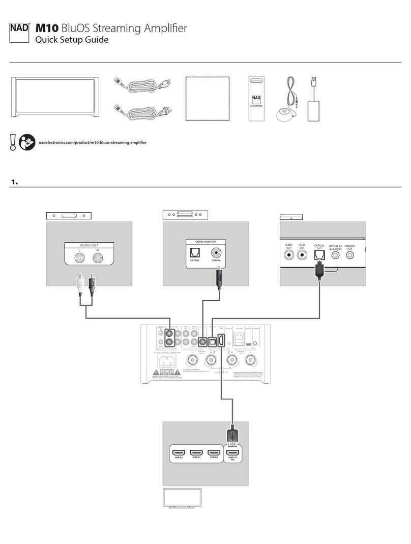
Rear panel features include jacks for speaker connections at 8R and 16R and the 2 way footswitch
for channel selection.
A buered eects loop is also tted with a level control and two recording out jacks which have
a tailored response to emulate a 412 cabinet. One of these is a “live”socket which enables the
amplier to still power the speaker, whilst the other is “dead” and mutes the amplier for silent
recording.
Finally located on the front panel are the two push switches that change between channels
1-2 and 2-3 (note that these switches need to out for the footswitch to work if connected).
Dave Green.
Chief Engineer
HAYDEN HGT-A & P User Manual
www.haydenamps.com
The Hayden HGTA
out of the box
Now that you have your amplier unpacked it’s time to get straight into using it so begin by
following these simple instructions:
Before using set all the EQ controls to 12 o’clock and all the volume, master and reverb controls
to zero, make sure the two push buttons are out (ie in the o position ) and that the speaker is
connected to the amplier, next switch the amplier on, (the push buttons should now have a
blue halo round them), allow the amplier to warm up for a minute and plug in your guitar.
Begin by advancing the volume control on channel 1 to a level that is comfortable and play
away, test the bass and treble controls and set to a tone you like, skipping now to the other side
of the front panel reverb can be added.
Next turn the gain control on channel 2 up to 12 o’clock and push in the channel 1-2 button,
a small red indicator will illuminate next to the switch, whilst playing gently turn the master
2 knob until you reach a volume level comparable with the clean tone you already have. By
adjusting gain 1 more or less crunch can be dialled in, any adjustment at the gain end will
require adjustment at the master end. Once you have these two channels balanced move onto
channel 3.
Activating the second push button brings in channel 3, with the gain set at 12 o’clock adjust the
master for the desired volume level.
At this point it’s worth experimenting with the contour and EQ controls to “get your sound”, all
the controls are interactive so adjusting one will move the others, sounds tricky but you will nd
them very easy to use, this type of EQ has been around 60+ years.
Now plug the footswitch into the jack socket or the rear of the unit and release the channel
buttons on the front panel. These buttons will override the footswitch so they have to be OFF for
the footswitch to work!.

HAYDEN HGT-A & P User Manual
www.haydenamps.com
The Hayden HGTA
recording
There are two recording out sockets on the rear panel, one LIVE and one DEAD, the output from
these has a tailored repose curve to emulate a 412 cabinet, you can use either to record what
you are playing as follows:-
Using the LIVE socket allows the amplier to produce sound so you can hear what you are
playing and you will still have the interaction between the amplier and your instrument.
The DEAD socket cuts o the amplier so you will need to monitor what you are playing
through an alternative device .**(although the amplier is not producing sound the speaker
MUST remain connected!)
effects loop
Eects send and return sockets are also tted to the rear panel, place eects within the loop and
experiment to arrive at the best settings, the level control should initially be set to minimum to
avoid overdriving the eects used.
Any eects that have an output level control will now function as an overall master volume
so carefull adjustment will be needed to get the best results, also try changing the order of
the pedals round as the position in the chain will give diering results. As a general rule drive/
distortion and wah pedals should be placed between the instrument and the amplier and only
pedals that you want to act on the whole of the sound should be placed in the loop, say chorus/
ange/echo etc.
As an example an echo pedal with several diminishing repeats placed in between the
instrument and the amp on an overdrive sound would give diminishing quantities of distortion
on each repeat ,whereas placing the pedal in the loop would give constant distortion on each
repeat. The rule here is to experiment to give you the results you are looking for.
HAYDEN HGT-A & P User Manual
www.haydenamps.com
The Hayden HGTA
GENERAL NOTES
Valve ampliers require care and attention to get best results and reliable operation, follow these simple
rules and you should get years of faithfull service.
• Takecarewhensettingtheamplierup,especiallytheroutingofthesignalleads
(ie instrument FX leads etc) try to keep these away from the speaker to avoid unwanted noise
• Athighgainandvolumelevelsyouwillneedtostandfurtherawayfromtheampliertoavoid
unwanted noise and feed back
• Withsinglecoiltypepickshumcanbeaproblem,eitherfrombeingstoodtoclosetothe
amplier or from the room itself, typical sources of hum are power supplies, computers, low
voltage halogen and uorescent lighting, energy saving bulbs etc.
• Cracklingnoisecanresultfromcentralheatingandrefrigerators,worthrememberingifyouget
annoying pops etc. when you are trying to record at home.
• Mobliephonescancausesomeinterestingnoisesandinterferenceespeciallyifplacedontop
of the amplier or in your pocket.
be safe
• Keeptheamplierdryanddon’tstanddrinksorothercontainersofliquidsonit.
• Storetheampliersomewheredry,awayfromcondensationetc.
• Whenusingtheamplierdon’tcovertheventilationholesoruseitnexttoaradiatoretc.
• Alwaysusegoodqualityleadsforconnectingtheinstrumentandspeakertotheamplier.
• Checkthemainscablesfromtimetotimereplaceifdamagedinanyway.
• Havetheamplierservicedatleastonceayearespeciallyifyougigonaregularbasis,Valvesarefragile
and usually fail due to rough handling and vibration, combos use more valves than heads as a rule due
to the valves being in the same cabinet as the speaker. Many crackling noises are a direct result of a
failing valve.

HAYDEN HGT-A & P User Manual
www.haydenamps.com
The Hayden HGTA
user notes
Use these blank panel drawings to note down somwe of your favourite settings.
HAYDEN HGT-A & P User Manual
www.haydenamps.com
BASIC PRECAUTIONS
WARNING - When using electrical products,
basic precautions should be followed,
including the following:
1. Read all the instructions before using the
product.
2. Do not use this product near water – for
example, near a bathtub, washbowl, kitchen
sink, in a wet basement or near a swimming
pool.
3. This product may cause permanent hearing
loss. Do not operate for long periods of time
at a high volume level or at any level that is
uncomfortable. If you experience any hearing
loss or ringing in the ears, you should consult
an audiologist.
4. Make sure nothing interferes with the
ventilation of the product when in use.
5. The product should be located away from
heat sources such as radiators, heat registers,
or other products that produce heat.
6. The product should be connected to a
power supply of the type described in the
operating instructions or as marked on the
product.
7. The power supply cord of the product
should be unplugged from the outlet when
left unused for a long period of time.
8. Care should be taken so that objects do
not fall and liquids are not spilled into the
enclosure through openings.
9. The product should be serviced by
qualied personnel when:
a. The power supply cord or the plug has
been damaged; or
b. Objects have fallen, or liquid has been
spilled into the product: or
c. The product has been exposed to rain
or moisture: or
d. The product does not appear to
operate normally or exhibits marked
change in performance: or
e. The product has been dropped, or the
enclosure damaged.
10. Do not attempt to service the product.
All servicing should be referred to qualied
service personnel.
11. For continued protection against the
risk of re, replace fuses only with those of
the same type and rating as indicated on the
back of the product.
WARNINGS USED ONTHE EQUIPMENT
GROUNDING INSTRUCTIONS
This product must be grounded (earthed).
If it should malfunction or break down,
grounding provides a path of least resistance
for electric current to reduce the risk of
electric shock. This product is equipped
with a supply cord having an equipment
grounding conductor and a grounding
plug. The plug must be plugged into an
appropriate outlet that is properly installed
and grounded in accordance with the local
codes and ordinances.
DANGER - Improper connection of the
equipment grounding conductor can result in
a risk of electric shock. Check with a qualied
electrician or serviceman if you are in doubt
as to whether the product is properly
grounded. Do not modify the plug provided
with the product – if it will not t the outlet,
have a suitable outlet tted.
The wires in this mains cord are coloured in
accordance with the following code:
Green & Yellow - Earth
Blue - Neutral
Brown - Live
CE MARK FOR EUROPEAN
HARMONISED STANDARDS
The CE mark which is attached to
these products means it conforms
to EMC Directive (89/69/EEC), CE
mark Directive (93/68/EEC) and Low
Voltage Directive (72/23/EEC).
The lightning ash with the
arrow head symbol within
an equilateral triangle is
intended to alert the user to
the presence
of uninsulated ‘dangerous
voltage’within this product’s enclosure that
may be of sucient magnitude to constitute
a risk of electric shock.
The exclamation point within
an equilateral triangle is
intended to alert the user to
the presence of important
operating and
maintenance (servicing) instructions in the
literature accompanying this product.
Hayden Ampliers reserve the right to change specications without notice. E & O E. All contents ©Hayden 2011.
This manual suits for next models
1
Table of contents
