ECU Master PMU-16 User manual

ECUMASTER PMU-16/PMU-16DL
Preliminary Manual
(04.06.2018, rev. 1.02)
Page 1

ATTENTION!
•The ECUMASTER PMU is designed for mo orspor applica ions
only and canno be used on public roads!
•The ins alla ion of his device should be performed only by
rained specialis s. Ins alla ion by un rained individuals may
cause damage o bo h he device and he vehicle!
•Incorrec configura ion of he ECUMASTER PMU can cause
serious damage o vehicle componen s!
•Never modify he device’s se ings while he vehicle is moving as
i may cause an acciden !
•ECUMASTER assumes no responsibili y for damage caused by
incorrec ins alla ion and/or configura ion of he device!
•To ensure proper use of ECUMASTER PMU and o preven risk of
damage o your vehicle, you mus read hese ins ruc ions and
unders and hem horoughly before a emp ing o ins all his uni .
•Never shor -circui he wires of he vehicle's wiring loom or he
ou pu s of he ECUMASTER PMU!
•All modifica ions o he vehicle's wiring loom mus be performed
wi h he nega ive erminal of he ba ery disconnec ed.
•I is cri ical ha all connec ions in he wiring loom are properly
insula ed!
•The device mus be disconnec ed before performing any welding
on he vehicle!
Page 2

Table Of Con en s
ECUMASTER PMU ............................................................................................................... 5
Technical ............................................................................................................................ 5
Specification ....................................................................................................................... 6
SOFTWARE INSTALLATION ................................................................................................ 8
Compatibility ...................................................................................................................... 8
ownloading the PMU software ........................................................................................ 8
Installing PMU software ..................................................................................................... 8
CONNECTING PMU TO PC ................................................................................................ 11
CAN – USB interface ....................................................................................................... 11
ECUMASTER USBtoCAN interface ................................................................................ 11
ECUMASTER USBtoCAN pinout .................................................................................... 12
Connecting USB interface, wiring schematics ................................................................. 13
PMU status ...................................................................................................................... 13
CAN protocol, CAN topology ........................................................................................... 14
USING PMU SOFTWARE ................................................................................................... 15
Launching PMU software ................................................................................................. 15
Using PMU software ........................................................................................................ 15
PMU Client workflow ........................................................................................................ 17
ELEMENT TYPES ............................................................................................................... 19
Analog Input ..................................................................................................................... 19
Power Output ................................................................................................................... 19
CANbus Message Object (Mob) ...................................................................................... 19
CANbus Input ................................................................................................................... 19
CANbus Keyboard ........................................................................................................... 19
Switch .............................................................................................................................. 19
Number ............................................................................................................................ 20
Function ........................................................................................................................... 20
Wipers Module ................................................................................................................. 20
Blinkers Module ............................................................................................................... 20
CANbus Export ................................................................................................................ 20
MANAGING ELEMENTS .................................................................................................... 20
Saving elements .............................................................................................................. 20
Loading saved elements .................................................................................................. 20
FUNCTIONS ........................................................................................................................ 21
Main Principle .................................................................................................................. 21
Operations ...................................................................................................................... 21
Function examples .......................................................................................................... 23
CHANNEL LOGGING .......................................................................................................... 25
Graph Log ........................................................................................................................ 25
Logging Frequency .......................................................................................................... 26
Custom Log ...................................................................................................................... 26
PMU PINOUT ....................................................................................................................... 27
Output Pins ...................................................................................................................... 28
Input Pins ......................................................................................................................... 28
PMU TEMPERATURE, PLACEMENT AND LOAD BALANCING ..................................... 28
PMU Placement ............................................................................................................... 28
PMU Temperature ............................................................................................................ 28
Output Load Balancing .................................................................................................... 29
Page 3

Output Pin signaling and status ....................................................................................... 30
WIRING ................................................................................................................................ 31
Basic diagram .................................................................................................................. 31
Wire Size .......................................................................................................................... 32
Load examples for popular devices ................................................................................. 32
ANALOG INPUT WIRING ................................................................................................... 33
Wiring schematics ............................................................................................................ 33
Analog Sensor ................................................................................................................. 36
OUTPUT DEVICES .............................................................................................................. 37
Power Output ................................................................................................................... 37
Simple Power Output Setup ............................................................................................ 38
Wipers .............................................................................................................................. 40
Blinkers ............................................................................................................................ 41
CANbus Keyboard ........................................................................................................... 42
Exporting Keyboard state ................................................................................................ 43
Using CANbus Keyboard to signal status ........................................................................ 43
Using output pins in parallel ............................................................................................. 45
INERTIA SWITCH ................................................................................................................ 45
Inertia Switch ................................................................................................................... 45
MASTER RETRY CHANNEL .............................................................................................. 46
PWM (PULSE WIDTH MODULATION) ............................................................................... 46
Soft Start .......................................................................................................................... 47
uty Cycle ........................................................................................................................ 47
Using flyback diode .......................................................................................................... 48
USING MULTIPLE PMUs .................................................................................................... 49
Basic iagram .................................................................................................................. 49
Communication ................................................................................................................ 49
Using PMU Client with multiple PMUs ............................................................................. 50
CAN STREAM ..................................................................................................................... 51
CANbus Export ................................................................................................................ 51
CANbus Input ................................................................................................................... 51
Importing .CANX File ....................................................................................................... 52
Standard CAN Stream ..................................................................................................... 54
DOCUMENT REVISION HISTORY ..................................................................................... 58
Page 4

ECUMASTER PMU
ECUMASTER PMU is an inteligent power management unit designed to replace the old, traditional
and often unreliable fuses and relays. PMU is not only an electronic switch, but a device that can
perform all kinds of advanced operations, validate logical conditions, manage abnormal situations,
as well as log its parameters for you to have an oversight. PMU allows you to power up external
devices such as fan, blinkers, wipers, oil pump etc. and create advanced strategies for those
devices using logic with failsafes, condition checking and many more functions. It can
communicate and work in tandem with other ECUMASTER CAN devices. It is equipped with over
and under current protection, surge protection, 3 gyroscope, accelerometer, LE Status lights,
Soft Start, Pulse Width Modulation with uty Cycle control and more.
Technical
Page 5

Specifica ion
GENERAL
Temperature Range ACEQ100 GRADE1 (-40 to 120C)
CPU 32 bit automotive, 90MIPS
Rever e polarity
protection
Ye , internal up to 16V
Operating voltage 6-22V immunity to tran ient according to ISO 7637
Enclo ure IP65, be poke CNC machined aluminium
Size and weight 131x112x32.5mm, 345g
Connector 1 x 39 Automotive connector
1 x M6 tud for battery connection
PC communication CAN (Peak CAN, ECUMASTER USBCAN, Kva er)
Multiple PMU Up to 5 PMU can work in tandem
OUTPUTS
10 x high ide 25A output Overcurrent and overheating protection.
Output may be paired to increa e continuou current capability.
Current and voltage mea ured for each output.
Inductive load clamp: Vbat - 36V
Inductive energy di ipation Ear: 460mJ
Peak current: 120A
6 x high ide 15A output Overcurrent and overheating protection.
Output may be paired to increa e continuou current capability.
Current and voltage mea ured for each output
Indoctive load clamp with diode to: -0.5V
Peak current: 120A
Total current output 150A continuou
Output current control tep 100mA
PWM Ye , available for each 25A output
Programmable variable Duty Cycle control for each output
Separate frequency etting ranging from 4Hz to 400Hz for each output
Soft Start Ye , available for each 25A output
Low ide wiper braking
output
Dedicated output with wiper braking feature.
Pin hared with output #8
Current limit: 6A
+5V monitored 5V, 500mA output for powering external en or
INPUTS
Page 6

Analog Input 16 input , 10 bit re olution, 0-5V (protected), with oftware electable
10K Ohm pullup and pulldown
CAN Keypad 2 x Ecuma ter keypad (4, 6, 8, 12 key ), LifeRacing PDU Keypad
OTHER
Output tate indication 16 bicolor LED
Accelerometer/Gyro cope 3D accelerometer with 3D gyro cope for logging and cra h detection
Real Time Clock Ye , uper capacitor for backup power (up to 3 day )
CAN BUS
CAN interface 2 x CAN2.0 A/B
CAN tandard 2.0A/B 125, 250, 500, 1000 Kbp
Input/Output Stream U er defined with bit ma king
Up to 48 input me age
LOGGING (PMU16DL only)
Logging Memory 256 Mbyte
Logging Speed Variable, defined per channel, up to 500Hz
PC LOGGING
Logging Speed Variable, defined per channel, up to 500Hz
FUNCTIONS
Logical Operation i True, i Fal e, =, !=, <, <=, >, >=, AND, OR, XOR, Fla h, Pul e,
Toggle, Set/Re et Latch
Number of function 100
Number of operation 250
Update frequency 500Hz
Special function Wiper , Blinker
Page 7

SOFTWARE INSTALLATION
Compa ibili y
PMU Software is compatible with Windows XP/Vista/7/8/8.1/10.
Downloading he PMU sof ware
To configure PMU device a PMU Client must be used (both PMU16 and PMU16 L use the same
client). To download PMU software please head to www.ecumaster.com/pmu page.
Ins alling PMU sof ware
To install PMU software, double click the downloaded “PMUSetup_X_XXX_X.exe”.
Click Next to proceed.
Page 8

Choose which folder to install the PMU Client to.
Choose wheter you want a desktop icon or not.
Page 9

This is the summary of your installation, if both the folder and icon choice are correct, press Install
to proceed. If not, you can go back to make a quick correction.
After the installation is finished, you can choose to launch PMU Client right away.
Page 10

CONNECTING PMU TO PC
CAN – USB in erface
To properly connect PMU to PC using USB 2.0 a special interface must be used. PMU Client
supports three interfaces:
•ECUMASTER USBtoCAN interface (can be bought directly from www.ecumaster.com)
•PEAK Systems PCAN-USB
•Kvaser USBcan
Each interface must have its drivers installed.
Interface must be bought separately.
ECUMASTER USB oCAN in erface
To use ECUMASTER USBtoCAN interface, user must be equipped in following items:
•USB A to USB B adapter to connect the interface to PC
•B-9 Cable to connect interface to PMU
•ECUMASTER USBtoCAN interface drivers, available at:
http://www.ecumaster.com/products/usb-to-can/
To install drivers run EUSBtoCAN_Driver_v1.0.exe and follow installation instructions.
Basic cable connection should look like this.
ECUMASTER USBtoCAN also has LE signaling ability:
Color Descrip ion
Green Continuou Device turned on
Green Fla hing Device turned on and connected to PC
Green and Orange Fla hing Data tran fer in progre
Orange Continuou Device turned on, currently in bootloader
Orange Fla hing Device turned on, firmware update in progre
Red Continuou Temporary CAN communication error
Red Fla hing Permanent CAN communication error
Page 11
USBtoCAN connection

ECUMASTER USBtoCAN is equipped with 120Ohm CAN terminator which can be switched on or
off by user. Picture below shows terminator switch location:
ECUMASTER USB oCAN pinou
Page 12

Connec ing USB in erface, wiring schema ics
To connect PMU to PC, CAN1 CANbus must be used. This is the CAN provided for us for PC
communication. To wire the USB - CAN interface, CAN1H and CAN1L pins (See PMU Pinout
section) must be used. Twisted pairing is also recommended. CANbus must also be terminated at
both ends of the bus. ECUMASTER USBtoCAN is equipped with one terminator that can be
switched on or off (See ECUMASTER USBtoCAN inter ace section).
If the Interface is connected, PMU must be supplied with power, both on the +12SW Pin (See PMU
Pinout section) and the M6 stud.
Here is a simple diagram of USB connection, please note that it assumes that the second
terminator is applied by the USBtoCAN interface:
PMU s a us
PMU device is fitted with LE that signals status of the PMU device.
Picture showing the LE location:
There are 6 possible states of PMU LE :
Color S a us
Green Continuou Device i active
Orange Continuou Device i active and connected to PC
Green Fla hing Slowly Device i waiting for Firmware Upgrade
Orange Fla hing Slowly Device i performing Firmware Upgrade and i connected to PMU
Page 13
PMU - PC communication
ATTENTION !
Ground wire connec ion be ween USB oCAN and PMU-16 can be DANGEROUS!
Ground connec ion is only allowed if devices before connec ing have he same ground po en ial.
Po en ial difference can be checked by using vol ome er be ween corresponding grounds.
Client
Orange Fla hing Fa t Device i performing Make Permanent operation
Red Continuou Device Error - plea e contact the di tributor or manufacturer directly
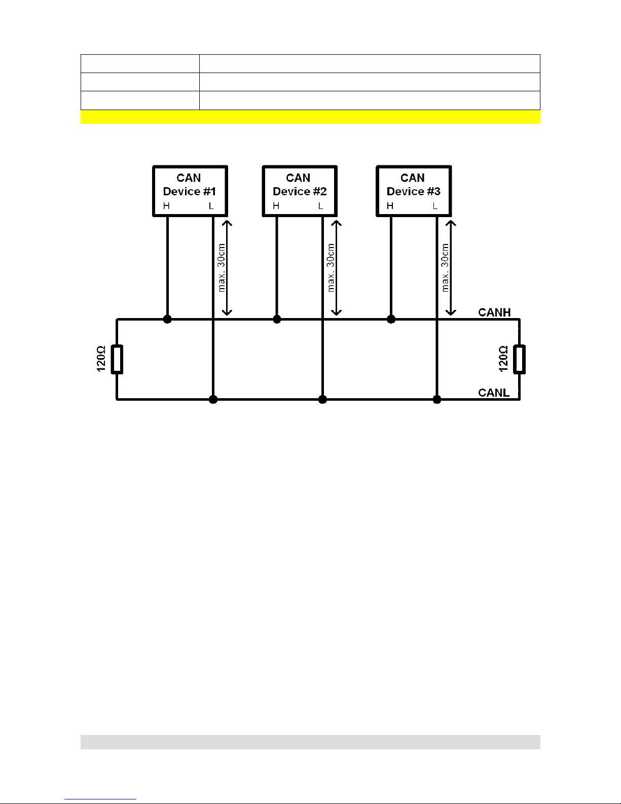
CAN pro ocol, CAN opology
CAN topology looks like this:
For 1Mbit/s connection (CAN 1), following rules must be abided:
•Maximum unterminated cable length from device to CANbus is 30 cm
•Maximum bus length is 40m.
•Maximum of 30 nodes
•120 Ohm terminators must be applied at both ends of CAN bus.
•Twisted pairing is required.
For 500kbit/s connection (CAN 2) following rules must be abided:
•Maximum unterminated cable length from device to CANbus is 30 cm
•Maximum bus length is 100m.
•Maximum of 30 nodes
•120 Ohm terminators must be applied at both ends of CAN bus. PMU is equipped with
CAN2 terminator which can be turned on or off via PMU Client (Tree View → CAN Setup)
•Twisted pairing is required.
Page 14
CAN Topology

USING PMU SOFTWARE
Launching PMU sof ware
To run PMU software either doubleclick the icon on desktop, or use start menu to find it.
Using PMU sof ware
When PMU Client is launched for the first time, user will be asked to enter the name of his device.
All projects will then be saved to the directory corresponding to devices name.
After entering the Client, main window will appear:
Using the Client is pretty straightforward. The Project Tree window is the most significant one. You
can use it to set up analog inputs, configure power outputs, create functions etc.
To create elements, either use the toolbar with icons located on Project Tree window, use Alt + A
Keyboard shortcut or click Add button, then select the type of element you want to create.
Page 15
De ault Dekstop/Main Window with highlited Project Tree window
New device name

To upload current project to on-device flash memory, either use the Make Permanent button, or
use F2 keyboard button. The PMU status LE will flash with orange color (See PMU Status
section).
To save a copy of your current project on hard drive either use Ctrl+S keyboard shortcut, or use the
Clients toolbar.
Right on the main screen there are also windows with monitoring functionality. They are updated in
real time and show various parameters reported from particular pins as well as values of elements
created by user.
Page 16
Project Tree, adding new Elements
Monitoring Windows

On the left, there is a Tree View double clicking any item on it, will bring up it's window to current
desktop.
PMU Clien workflow
PMU Client workflow is really simple. You can monitor parameters of your channels, make
adjustments, follow the graph log to understand channels behavior, you can create elements, then
use those to control other elements or channels.
Elements and channels in this case can be anything, Power Output, Analog Input, Function, Switch
etc.
Let's take a look at two more in-depth use cases.
Page 17
Tree View

These are just two examples of how PMU Client can be used, but the possibilities are endless.
Page 18

ELEMENT TYPES
Analog Inpu
Analog inputs are input devices connected directly to the PMU.
Below is the list of analog inputs supported by PMU.
•Switch - Active High
•Switch - Active Low
•Rotary Switch
•Analog Sensor
Head to Wiring section to see wiring diagrams for each type of analog input.
Power Ou pu
Power Outputs are devices powered by PMU which are connected to particular output pins.
Power Output examples:
•Fuel Pump
•Fan
•Oil Pump
Every Power Output has over current, under current (both user configurable) and overheat
protection. They can be either turned on by default, controlled by function or triggered by another
element such as Analog Input
CANbus Message Objec (Mob)
CANbus Message Objects are interfaces needed for data gathering from CAN Stream. They read
a particular number of frames (user defined, up to 8) starting from particular I (also user defined)
from chosen CANbus. Maximum of 8 CANbus Message Objects can be created for each CANbus.
They also have special timeout flag which can be used to set up a different strategy if a connection
from another CAN device times out.
CANbus Inpu
CANbus Inputs use CANbus Message Objects to extract data from chosen frame. They are able to
read a user defined number of bits starting from user defined position, then apply offsets, division
or multiplication to the extracted data.
CANbus Keyboard
CANbus Keyboard is an element that provides communication with Keyboard. It is used to define
and handle Keyboard buttons, set their color, type etc.
Swi ch
You can use two types of switches:
•Latching Switch – switches between user defined number of states.
•Press Hold Switch – short press switches between high and low state, holding it triggers
third state.
Page 19

Number
Number is simply an integer. It can be either a typed in constant or value of chosen channel.
Number is mostly used for comparison or to control Duty Cycle in Pulse Width Modulation (See
PWM section).
Func ion
Function is one of the most important elements. It can be used to create a set of rules, conditions
to Power on an output device. Function always evaluates to either 0 or 1. If the function is used as
control channel for a Power Output, the Power Output will be turned on if function returns 1 and
turned off if function returns 0. Functions will be explained in depth later on in Functions section.
Wipers Module
Wipers module is a separate module to control the Wipers. It consists of two Power Outputs for
slow and fast wiper speed and an Analog Input for Park Switch. To use park functionality, Output
Pin O8 is provided to use for slow wiper speed. To see the wiring instructions, head to Wiring part
of the manual.
Blinkers Module
Blinkers module is a bit like Wipers Module, it is a separate element which controls the blinkers. It
consists of two Power Outputs for left and right blinkers and needs three inputs (ie. CANbus
Keyboard) to control the Left Blinker, Right Blinker and Hazard Lights.
CANbus Expor
CANbus Export allows you to broadcast (send) data to the CANbus, which then can be used by
other CAN device. For example, you can transmit the status of a Fan to other PMU or EMU Black
MANAGING ELEMENTS
Saving elemen s
Most elements can be saved to hard drive. To save your element, click icon on elements
toolbar and choose where you want to save it.
Loading saved elemen s
Elements that can be saved, can also be loaded. To load your element, click icon on elements
toolbar and choose file to load.
Page 20
This manual suits for next models
1
Table of contents
Popular Portable Generator manuals by other brands

Olympus
Olympus ESG-410 Instructions for use

Siemens
Siemens SINAMICS S120 manual

Champion Global Power Equipment
Champion Global Power Equipment 201185 Operator's manual

Rheem Manufacturing
Rheem Manufacturing GEN12AD Operator's manual

Pramac
Pramac E3750 user manual

Coleman
Coleman Powermate PM0543002 Insert


