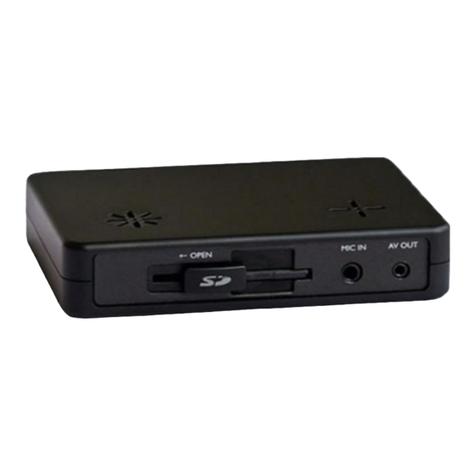
Eddy Wireless SD Cards Series User manual

W 2 0 1 2 P

W 2 0 1 2 P
CHAPTER 1:PRODUCT APPLICATION AND PARAMETER--------------------------------------
CHAPTER 2:PRODUCT INTERFACE DEFINITIONAND FUNCTION DESCRIPTION-------
2.1:MDVR Out-design andDimension---------------------------------------------------------
2.2:Definition of functionalMDVR back panelinterface-----------------------------------
2.3:Definition of simpletype MDVR'S backpanel interface------------------------------
2.4:Brief instruction ofcommonly used interfacecable----------------------------------
2.5:USIM card installation------------------------------------------------------------------------
2.6:Instructions of functionkeys on remotecontroller------------------------------------
CHAPTER 3:SYSTEM OPERATION MENU----------------------------------------------------------
3.1:Demo working anduser login---------------------------------------------------------------
3.2:System menu constructionchart-----------------------------------------------------------
3.3:System setup------------------------------------------------------------------------------------
3.3-1:Basic-------------------------------------------------------------------------------------------
3.3-2:Power off/on setup-------------------------------------------------------------------------
3.3-3:Network setup-------------------------------------------------------------------------------
3.3-4:Password setup------------------------------------------------------------------------------
3.4: Recording setup--------------------------------------------------------------------------------
3.4-1 :Mormal setup--------------------------------------------------------------------------------
3.4-2 :Channel setup-------------------------------------------------------------------------------
3.4-3 :Timing setup--------------------------------------------------------------------------------
3.4-4 :Sub-stream setup-------------------------------------------------------------------------
3.5 :Vehicle information---------------------------------------------------------------------------
3.5-1 :Sensor setup-(alarminput)--------------------------------------------------------------
3.5-2 :G-Sensor setup-----------------------------------------------------------------------------
3.5-3 :Speed setup---------------------------------------------------------------------------------
3.6: TOOLS--------------------------------------------------------------------------------------------
3.6-1:Format disk management----------------------------------------------------------------
3.6-2:Configure manage andlog search-----------------------------------------------------
3.6-3:Motion detection---------------------------------------------------------------------------
3.6-4:System upgrade----------------------------------------------------------------------------
3.7 MODULE MANAGE-----------------------------------------------------------------------------
3.7-1:3G setup--------------------------------------------------------------------------------------
3.7-2:WIFI setup------------------------------------------------------------------------------------
3.7-3:PTZ set up------------------------------------------------------------------------------------
3.8 :System information---------------------------------------------------------------------------
3.9 :Recording playback---------------------------------------------------------------------------
CHAPTER 4: COMMONSHORTCUT SETUP------------------------------------------------------
4.1 :Cables testingand power on----------------------------------------------------------------
4.2 :Recording setup-------------------------------------------------------------------------------
4.3 :PTZ connectionand setup-------------------------------------------------------------------
4.4 :Playback recordedfiles on PC--------------------------------------------------------------
4.5 :Vehiclefast connecting toCMS------------------------------------------------------------
APPENDIX1 : CMSPLATFORM INTERFACE------------------------------------------------------
APPENDIX2 : FAQ---------------------------------------------------------------------------------------
APPENDIX3 : CORRESPONDINGTABLE OFSTORAGE SPACE------------------------------
Contents 1
4
4
5
6
6
7
8
9
9
10
10
10
11
11
11
12
12
13
13
13
14
14
14
15
15
15
16
16
17
18
18
19
19
20
20
22
22
22
24
25
26
27
28
30

W 2 0 1 2 P
1.1 MDVR is a cost-effective, function extensibile equipment which is designed for on-board video
monitoring and remote monitoring, It uses the rapid handling device and embedded Linux platform,
combined with the most advanced H.264 video compression / decompression technology , network
technology and GPS technology . With SD card as a storage medium,MDVR can realize many functions
such as audio-video recording , vehicle's driving information recording , remote management and GPS
signal upload . Withcentral control software, itcan realize the central control of alarm linkage , remote
management and playback analysis .With simple and modern appearances, MDVR is vibration-proof ,
installation-friendly, has powerful functions and stable performances, etc.
CHAPTER 1:PRODUCT APPLICATIONS ANDPARAMETERS
FORM 1 : MDVR PRODUCT'S SPECIFICATION PARAMETERS
1
1.For Simple model(aviation head model), local recording is the main function
2.CMS client terminal manages 3G/ WIFI modules.
3.WIFI/3G/ GPS modules are optional.
Items
System
Video
Parameters
Language
OSD
Password
Video input
Video output
Preview
Recording Ratio
Image Compression
Audio input
Audio output
Recording mode
Video format
Video stream
Specifications
Chinese/English
Graphical User interface OSD menu
Users Password/Administrator Password
4CH VIDEO INPUT 1.0Vp-p 75
1CH VIDEO OUTPUT 1.0Vp-p 75
1 CH/ 4CH Preview.
PAL 25 Frame/s NTSC 30 Frame/s
H.264 Main profile 100fps/s
4-CH
1-CH
Audio & Videosync.
D1/HD1/CIF
ISO14496-10
D1: 2048Kbps ~400Kbps
Audio
Audio Bitrate
Storage
Alarm input
Alarm output
Rs485 Interface
RS232 Interface
WIFI Interface
control panel
Audio power amplifier
3G(HSDPA/WCDMA)
Built-in GPSmodule, Geographic co-ordinates, speed can be read in coding
flow, and can be wireless uploaded. optional
Built-in G-Sensor
PC playback
CMS
Support SDcards upgrade.
HD1: 2048Kbps ~380Kbps
8 levels optional. Highest:1 level
8KB/s
Support 1 or2SD cards, maximum32GB for each.
6 alarm input, 2 alarm input,
2 alarm output, high level 12Voutput
Support 2-RS485 interface Support 1-RS485 interface
Support 1-RS232 interface
802.11b/g no
Connect to stationreporter or controlpanel no
Support 2-ch audiopower amplifier output no
Optional 3G(HSPA/WCDMA))module
Video playback onPc and analyse thevehicle info inthe file
Video preview viaWIFI GPS upload alarm upload,
central command andparameters configuration, etc.
Alarm
Communication
Port
Extended
interface
WILESS
GPS
G-SENSOR
Software
Upgrade
Video Rate kbps
Image
processing &
storage
SD CardMobile DVRUser Manual
1
CIF: 1536Kbps ~128Kbps

W 2 0 1 2 P
FORM 2 :MDVR BASIC ELECTRICALPARAMETERSLIST
1.2 MDVR PRODUCTAPPLICATIONCONNECTION SCHEMATIC DIAGRAM
Figure1-1, MDVR canbe used bothin common andspecial vehicles videomonitoring or remote
monitoring such asbus , logisticscar , freightcar , long-distancetravel bus ,taxi , tanker, school bus,
police car ,patrol car etc. Front endacquires signal byon-board special camera, through specialvideo
line transfer itto MDVR mainframeto process videocompression , localstore in SDcard. Model with
3G module canrealize remote monitoring,recording, upload etc.Model with GPSfunction can realize
real time vehiclepositioning; Schematic diagramis a commonapplication mode, theactual use of
various functions willbe changed asthe existence ofthe modules change.
Items
12V
4V
5V
75
<4V
4V
-40 -80
Specifications
8V 36V,When long-term under8V,or long-term over36V,
auto power off,and enter protectionmode.
12V +/-0.2V Max:2A.
OFF
On
75Ùfor each videoinput impedance
Input 2Vp-p CVBSanalog signal, revealdevice input need75Ù
impedance to fit
Low level alarm
High level alarm
1.Maximum 32GB foreach card.
2.SD-card for storage,support recording andsystem upgrade, etc.
Under well-ventilated enviroment.
DC8-36V
2Vp-p
1or 2 SD Cards
Power input
Vehicle keysignal
Video output Volt
I/O interface
SD-card interface
Operating Temp
Impedance
Power output
Parameters
1:Simple model without 3G and WIFI, butonly with SDcard local storage or GPS ;
2:CMS client terminal and server device is relative tomodels with 3G andWIFI
module.
Figure 1-1 Autodown
file server
Database
server
Access
Gateway
server
Stream
media
server
File
storage
server GIS
server
Client Client
Control Panel Monitor Speaker Alarm
MDVR
2
SD CardMobile DVRUser Manual
2

W 2 0 1 2 P
1.3: MDVR NOTICE:
Tomake sure MDVRsafety use, acquiresatisfactory performance, andextend the servicelife
of the equipments, please fullyconsider the followingfactors when installthe equipment :
1.When install andoperate the equipment, please obeyall the electronic products guide, vehicles
and other connectionequipments requirements
2.Power supply andequipment grounded :Direct input rangeof the machinepower supply isfrom
DC 8V-36V, please dont get inverse,and.inputcan t be shortcircuit.Please note thepower supply
capacity of thepower line. Eventhe equipment isshut down ,it may becharged . pleaseavoid short
circuit . Beforeconnect with otherexternal devices, pleasecut the connectionbetween this
equipment and thepower supply.The input modeof equipment sensoris level mode, with external
voltage below 4Vis considered aslow level ,above 4V andbelow 30V isconsidered as highlevel.
Beyond 30V willdamage the equipment.Correctly connect theearth wires ofthe device andthe
vehicle and forma loop; Ifdon t use themachine for along time .It s better tocut the powersupply
completely to extend the service life
3.Humidity requirements :Install equipment indry environment, avoiddamp, water-drop, water
spray and otherplaces. Don't takethe equipment installedin places wherewater will sagor wet
places liquid willdrip down ;Do not usewet hand totouch the equipment,Donot stand inthe water
or touch withother water placeswhile contact theequipment, it mayget electric shock
4.Installation position:
Toextend the lifeof the equipment,please try toinstall it inplace with weakvibration, such as
behind the driver'sseat .The equipmentshould be installedon the vehicle'sventilation installation
part .Equipment installedon the planeshould remain adistance of 6inches (15 centimeters)
away from otherobjects to assurethe air flowand heat dissipation; Don't installit on theenclosed
area, such ascar trunk. Thismachine can beright side installedor side loading.The equipment s
external wiring musthave the enoughintervals and externalflame retardant protection, to ensure
the wire notto be bentor leakage ofelectricity due towear and vibration;Ensure that equipment
away from heatsource of thevehicle, the equipmentcan't have sundrypile up around,prohibit
placing anything onthe equipment .
5.Equipment safety:
Ensure passengers orthe driver can'tintervene and damagethe equipment unit,camera, wire and
other accessories .Don't install theequipment near othercomponents of vehicle; When install
equipment components, camera,accessories and wire,launch vehicles maycause damage tothe
equipment, Keep thevehicles static duringthe installation process,to prevent equipmentfalling
from vehicles.
'
'
''
'
Installation notes:
1.Equipment contains theelectronic devices, pleasehandle gently duringtransport .
2.All installation andmaintenance must beexecuted by theprofessional qualified person.
3.This product cant be installed in partof the vehiclewhere there waserosion by rainor other
liquid for along time .
4.Installation and allmaterials must beable to withstandthe weight ofthe fuselage.
5.Keep fuselage awayfrom the heatsource, dust andstrong magnetic fields.
6.Do not putheavy objects onthe equipments.
7.Don't flush theequipment directly whileclean the Vehicles .
8.The equipment outputpower shall notconnect to devicesthat are notrecommended.
9.Don't insert fingeror some objectsfrom the gapwhile operate theequipments.
10.Without professional guide,please do notopen or unloadthe equipment.
11.Don't changeany modules whenthe mainframe ischarged.
'
3
SD CardMobile DVRUser Manual
3

W 2 0 1 2 P
47
162 80 180
5
138
CHAPTER 2: INTERFACE ANDDESCRIPTION OFTHE FUNCTIONS
2.1 MDVR OUT-DESIGN ANDDIMENSION
Figure 2-1
Figure2-3
Function type MDVRdimension and installationhole site (doubleSD card
machine), as shownin Figure 2-1
Unit mm
Panel Indicator Light
Description
V-OUT Video OUT
SD1/SD2:Recording SD card
indicator light ,Lightwill be on
when the SDcard exists.
REC:Light will beon when
recording
GPS:Light will beon when the
GPS module exists
POWER:Light will beon when the
power supply canwork normally
ALM:Light will beon when the
machine is inabnormal situation
WIFI: Light will beon when the
WIFI is ON
2G/3G: Light will beon when 3G
communication module exists
IR :Infrared sensor receiving
remote control signal
See Figure 2-2 : put the back of the SD card upside,insert it into
the SD card slot ,then pull on the card slot
LOCK : It can be power on normally only when the electricity is
locked to the LOCK gear. Open the electronic lock in working
period, the system will upload the SD card , delay power off
according to the menu setting.
SD-1 SD-2
Figure 2-2
Push the card s protection cap
towards right afterunlocked
128
5
162
47
80
138
Figure 2-4
Simple type MDVRsize and installationhole site
(single/double SD card)as shown inFigure 2-4
Panel Indicator LightDescription :
SD1/SD2:Light will beon When theSD
card exists.
REC:Light will beon when recording
GPS:Light will beon when theGPS
module exists.
POWER:Light will beon when the
power supply canwork normally
ALM:Light will beon when themachine
is in abnormalsituation
IR:Infrared sensor receivingremote
control signal
Figure 2-5 Figure 2-6
Figure 2-7
Use key to open the LOCK gear, open the SD card protection cover, as Figure 2-5 ,then put the back of the
SD card upside , insert it to the SD card slot , press it into the right place. As Figure 2-6 ,finnally , cover the
chassis.
LOCK:It can be powered on normally only when the electricity is locked tothe LOCK gear. In working period ,
open the electronic lock , the system will upload the SD card , delay power off according to the menu setting.
Unit mm
4
SD CardMobile DVRUser Manual
4

W 2 0 1 2 P
2.2: DEFINITION OFFUNCTIONAL MDVRBACK PANEL INTERFACE
AV-OUT CAM1 CAM2 CAM4 CAM4 POWER
DEFINITION OF FUNCTIONALMDVR BACK PANEL INTERFACE
AS SHOWN INFIGURE 2-8:
RS485 RS232
SENSORS SPEED
GPS Antenna 3G Antenna WIFI Antenna
EXTENSION OUTPUT
CONTROL PANEL
CANBUS
POWER IN
4CH Audio/VideoInput 4pin
AUDIO/VIDEO
OUTPUT
SPEAKER
Figure 2-8
RS485 RS232
SENSORE SPEED
BACKSIDE PANEL MOUNTSTEXTS INSTRUCTIONS TABLE ASFOLLOWING:
EXTENSION
Interface
WIFI Antenna Interface
GPS antenna interface
2 G /3 G antennainterface
The power inputinterface
Print interface
Extension interface
VIDEO output interface
Audio output interface
Bus interface
Sensor interface
Bus Speed pulse
input interface
RS485/RS232 interface
Speaker interface
Name
WIFI
GPS
2G/3G
DC8-36V
MCU
EXTENTION
VIDEO- OUT
AUDIO- OUT
CAN-BUS
SENSORS
SPEED
RS485/RS232
SPEAKER
Discribtion
Wireless Local area network antenna interface
GPS antenna interface
2 G /3 G antenna interface
The power input interface
System information adjustment interface
Control panel interface
Video output
Audio output
Bus electronic control network
Switch input interface, high level (> 4 V) is effective
Bus Speed pulse input interface , input bus Speed
pulse signal differential input
RS232&RS485 serial data communication interface
Audio power amplifier output
5
SD CardMobile DVRUser Manual
5

W 2 0 1 2 P
1--12VOUT
2--GND
3--A-IN
4--V-IN
2.3: DEFINITION OFSIMPLE TYPE MDVR'SBACK PANEL INTERFACE
AVIATION HEAD
VIDEO &AUDIO INPUT
Figure 2-9
GPS Antenna
POWER INPUT
VIDEO/AUDIO OUTPUT
1: Interface specifications, please referto table3, V-in &A-in with aviation head;
2: 2channel alarm input, 2channel alarm output, apair ofschool interface;
3: GPSis optional, without3 Gand WIFIfunction;
2.4:BRIEF INSTRUCTION OFCOMMONLYUSED INTERFACECABLE
Power cable:
As the following map shows, one end is a white plug with 6 pin, connect to the white of the equipment's
back pannel. Red and black cable to connect to the car's battery directly. The red cable is connected to
the positive electrode, the black cable is connected with the negative pole .The yellow cable is
connected tothe ignition line. Mainframe equipment opens automatically after opening the car with the
car key.Autodelay closes after closing the car . The yellow cable connects to the gear where the
car key open all the dashboard light. ( thegear before start the motor ).
Power cable
4PIN A/V test cable
Alarm cable
RS485 RS232
SENSORS SPEED
1.Ensure the batteryvoltage is between8V-36V beforeconnection. Otherwise, it
will burn outthe equipments .
2.After the cableis connected .please note theinsulation between thepower line .
Prevent burn outthe battery becauseof the shortcircuit .
Functional MDVR approximately hasabove kinds of accessories,the 4 pin test cable is just used
during the test, please do notuse it on theinstallation. When installed, recommend to use the 4 pin
audio extended cable. Function model MDVR need to use the 4 PIN-AV when connect to theaudio
input . it doesn't need to use this cable if it is only video input, and use the AV interface in the front
panel only.External interface of functional MDVR can choose from WIFI/3G/GPS, so therelative
module antenna is needed . Video cable of the simple MDVR is aviation head. So there will be
some differences between the corresponding interfaces .As Figure 2-11.
4PINA/V cable
4PIN-AV OUTPUT
Audio/video cable
Figure 2-10 FunctionalMDVR interface roughlymatched wiring
6
SD CardMobile DVRUser Manual
6

W 2 0 1 2 P
Alarm output are all level output , The drive ability is 200 MA, if you want larger power devices,
you must connect it to external relays. This is theoptoelectronic alarm wiring diagram ofAlarm output
MDVR alarm output
+24V
MDVR alarm output
For functional MDVR card, if support the wireless network communication, it need to install the USIM
card which is suit for WCDMA/EVDO. USIM card is on the communication board of the mainframe , use
a screwdriver to take down the flap cover from the bottom of the mainframe. Then you can see the USIM
card interface, press it to USIM interface. Please notice the right side and the opposite side. Use
thescrew fix the flap cover after installation.
MDVR SENSOR
Braking light
+12V
Braking vane
Figure 2-13
Figure 2-14
1234
2.5: USIM CARDINSTALLATION
Alarm inputand output
This equipment has six alarm input interface and two alarmoutput interface (simple type has
only twoalarm inputs).Alarm inputdetection areall leveldetection. It can connect to various
vehicles driving statussuch asbrakes ,turns ,door switches , buttons of emergent alarm . When
press thebrake vane,MDVR candetect thehigh level,or detect the low level.
'
GPS antenna
3G antenna
EXTENSION
WIFI antenna
SPEAKER
Power supply cable
RS485 RS232
SENSORS SPEED
AVIATION HEAD
A/V test cable AVIATION HEAD
A/V cable
FIGURE 2-11SIMPLE TYPE MDVRINTERFACE USUALMATCHEDCABLE.
FIGURE 2-12 MDVRUSES CORRESPONGDING CABLESACCORDING TOFUNCTIONS
Alarm cable
3.The yellow cable must be installedon the ignitionline , orthe equipment willnot
support the delayshut down ,and the lastvideo recording willbe missed .
4.The installation ofMDVR must getpositive electrode directlyfrom the battery. Please
don't use ironwire as theground line .or it willproduce negative pulseand jamming the
normal operation ofthe mainframe . The diameter of power supply thatthe positive
electrode and negativepole must above 1.5 mm
7
SD CardMobile DVRUser Manual
7

W 2 0 1 2 P
Power on /power off
LOGIN
INFO
Figure keys 1, 2, 3, 4
RETURN
PAUSE/STEP
GOTO
FRAME
PLAY
Forward
REW
Stop REC
Recording
NEXT
PREV
PTZ
NOTE: this functionis not used temporarily
If the videohas set thepassword, press LOGINkey to inputthe password.As the systemdoes
not have recoveryand reset function,please remember thepassword.
Information
Under the surveillanceimages, it canbe used toswitch between singleand four images
Press the imagesegmentation key toshow the 4images ;Under thesurveillance image .
press this key,it will showswitch sequence asfollows: CH1-CH2-CH3-CH4.
Exit to thelast sub menu.Finally return tothe menu settingand the surveillanceimages ;
Suspend key andsingle step keywhen playback videomaterial . Pressthe key oncecan
play one step.Then press theplay key toreturn to thenormal playing speed
Playing back ,It can jumpto point timeto start playing
Press this keyto frame
Button to play
The forward buttonwhen playback videomaterial . Thereare four gears:2X,4X,8X,16X.
The rewind buttonwhen playback videomaterial . Thereare four gears 2X 4X 8X,16X
Stop manual videobutton
Launch manual videobutton
In Playing processturn down tothe next page/nextfile;
In Playing processturn up tothe last page/lastfile;
Automatic, preset, adjustment,variable times +,variable times- ,focus+, focus-,aperture +,
aperture- PTZ PRESET RECALL BRUSH
F1 F2 F3 F1 is shortcut key , F2, F3is spare key
LOGIN
Power on /off(not
used Temporarily)
System information
Number key area
Exit / return
Picture adjustment
PTZ control
Direction key area
Play back operation key area
4 images segmentation
PTZ control key area
Shortcut key / test key
Delete/Cancel
2.6 INSTRUCTIONS OF FUNCTION KEYS ON REMOTE CONTROLLER
8
SD CardMobile DVRUser Manual
8
System information

W 2 0 1 2 P
CHAPTER 3 SYSTEM MENUSETTING INSTRUCTIONS
3.1: DEMO WORKING AND USERLOGIN.
Trun on thedevice after power supply and otherconnecting successfully and according to
installation guidance. Interface refer to 3-1and there are four-image monitoring interface
after the device start working.Press LOGIN button on the remote control,then direct into login
interface,as 3-3 for reference
Figure
Figure ""
INSTRUCTIONS:
Figure
DEVICE NUM: User set number for everydifferent device and it will show in the right of the number
input box. User enter the number as showing, one number only for one device .
USER NAME: Including admin and normal user, regular user permission only could enter into video
searching ,playback , information and other menu, but can not set the menu and data. Admin gets the
permission to modify the system parameters.
PASSWORD: Enter password according to theselected user name. When password is correct , select
down button move to LOGIN , and press ENTER to login., Whenpassword is incorrect, press
CANCEL and delete ,then reenter the correct password. Admin password is 111111, the main
interface after entering password is as showing as 3-4.
"" " "
""
Figure 3-1 Figure 3-2
System menu includes seven main menus: SYSTEM, RECORD, VEHICLE, TOOL , PLAYBACK ,
MODULE , INFO. Main menus isas Figure 3-4 shows:
Figure 3-3 Figure 3-4
1 All submenu settings must save ,then effect, otherwise invalid.
2. Check box iffilled means function selected , notfilled means function not selected.
3 Number inputs can use number button on the remote control enter directly or
use soft keyboard. Letter only can complete viasoft keyboard,press RETURN
button toget back . ""
9
SD CardMobile DVRUser Manual
9

W 2 0 1 2 P
3.3 SYSTEM SETUP
It isthe first menu in themain menu and it includes BASIC SETUP ;POWER SETUP ;NETWORK
SETUP AND PASSWORD SETUP . "
"
3.3-1 BASIC SETUP
Basic setting: Itis used for device system time and some basic function setting .
1.DATE FORMAT: Press ENTER to type Y-M-D/ D-M-N.
2.DATE ANDTIME Setup:Press ENTER ,and then press - or + to set the data,press enter
to confirm .
3.During operation timeout (can set from 30-3600 seconds) and device number modification, press
CANCEL to delete, and then press the number button .
""
"" """"
""
Figure 3-6 Figure 3-7
BASIC
POWER
NETWORK
PASSWORD
NORMAL
CHANNEL
TIME LIST
SENSOR
SPEED
G-SENSOR
FORMAT
CINFIGURE
UPGRADE
LOG
DETECTION
WIRELESS
WIFI
PTZ
SYSTEM
RECORD
VEHICLE
MODULE
INFO
SHORTCUT
PLAYBACK
LOGIN
TOOLS
3.2 SYSTEM MENUS CONSTRUCTIONCHART
SUB-STREAM
TEMPERATURE
Figure 3-5
10
SD CardMobile DVRUser Manual
10

W 2 0 1 2 P
3.3-3:NETWORK SETUP
1.CENTER :
The server IPis thesame as the CMS server IP. Control Port is the same with Gateway Server Port
Number. Usually is 8501
2.Server IP isthe IPthat MDVR uses to connect to theCMS platform via 3G or WIFI. Normally it isthe
fixed WAN IP. Our devices can support 3G and WIFI functions. If the devices do not have these
functions,this menu can be passed.
SETUP
"".
1:Press ENTER to switch ON/OFF.
2:Admin can modify the user password and admin password. The default password for admin
password is "111111",after password modification completed, exit the menu and use the new password
to enter the interface.
""
Figure 3-10
3.3-4 PASSWORD SETUP
Figure 3-11
1.Power on/offmode : Select from TIME/ACC mode,and press"ENTER" to switch.
ACC modemeans whenthe vehiclepowers on,the devicewill startworking. Recommend to select it
as the default mode. Timing mode means the device will turn on or power offduring the fixed time.
2.Delaying offsetting :when selectACC mode orTIME mode,can set delay off andthe timeis
3-240mins, aftersetting ,demowill continuethe delayingtime.
3.3-2 POWER OFF/ON SETUP
4."COMPANYNAME","VEHICLE NUM","DRIVER NAME""LINE NUM"Setting:Press "Enter" key
to pop up keyboard window, then use left/right/up/down/enter key to setup.
5. When turnon automaticadjustment function,in the default time , the system will adjust the time
via GPSautomatically whenit comesto the time for adjustment.
6.HOME PAGE : Thereare "DEV STA"and "QUAD" two options, QUAD is the normal monitoring
screen whenwe turnon the device. If select DEV STAsystem informationwill appear in the four
channels normalscreens .Itis equalthe functionwhen wepress thebutton"INFO".
Figure 3-8
YMD
30 ( )
06:00:00
Figure 3-9
5 MIN
06:00:00
22:00:00
11
SD CardMobile DVRUser Manual
11

W 2 0 1 2 P
3.4 RECORD SETUP
It includes: Normal setting, Channelsetting, timing settingand sub-stream setting. It can reach
the highest quality recording after settings. With default settings, the device will start recording after
powering on. But in order to reach better recording function, you can modify the related parameters.
Record menu is shown as Figure 3-13.
Figure 3-12 Figure 3-13
1.TV SYSTEM: Press "Enter" to selectPAL/NTSC system.
2.REC MODE: Press "Enter" to selectAuto/Alarm/Timing mode
3.PACKETTIME: It isthe time range when therecording video will be packed into onefile. Select
from 15/30/45/60 mins, and 15 and 30mins are thebetter options .
4.Automatic recording overwrite can be selected on /off,if the SDcard is full,the following recording
video will overwrite the first recording videos automatically.
5.ALARM PRE-REC TIME(S): When thealarm occurs, it will pre-record a periodof time andpack to
the Alarmrecording. ( 0-60s range)
6.ALARM RECDELAY(S):After thealarm stops, it will keeprecording a period of time and
pack into thealarm recording.
7.ALARM OUTPUTTIME(S): It means the alarm output time range when alarmoccurs and
connects to the output device.( 5-240s )
8.REC PROTECHTIME: It meansthe time that recordings are stored in the SDcards, during the
protection time, even if theSD card isfull with alarmrecordings, it will not beoverwrited, press
"enter" to select from 1/3/5/7/10/15 days.
9.REC VEHICLEINFO: Select ON/OFF. When enables this function, recordings will contain all the
alarm info, GPS info andother information which can be viewed viaplayback software.
10. 1-15 Optional.VOLUME OUT:
3.4-1 NORMAL SETUP
Figure 3-14
During settings modification, select menu to become green , then press nter to switch. Press
ancel and before input numbers. "E "
"C "
AUTO
TIMED
ALARM
15mins
30mins
45mins
60mins
1-15days
NORMAL SETUP
SYSTEM:
REC MODE:
PACKET TIME:
OVERWRITTEN:
ALM PRE-REC TIME(s)
ALM REC DELAY(s):
ALM OUTPUT TIME(s)
REC PROTECT TIME:
REC VEHICLE INFO:
15
12
SD CardMobile DVRUser Manual
12
VOLUME OUT: 15

W 2 0 1 2 P
SUB-STREAM
00:00--23:59 00:00--00:00
00:00--00:00 00:00--00:00
00:00--00:00 00:00--00:00
00:00--00:00 00:00--00:00
00:00--00:00 00:00--00:00
00:00--00:00 00:00--00:00
00:00--00:00 00:00--00:00
00:00--00:00 00:00--00:00
3.4-2 CHANNELS SETUP
1 Set some propertiesof each channel,suchas RES,
QUAl MIC AUDIO,VOLUME etc .
FR: 1-25 optional,whenreach 25 FRit is real-time
recording. 1-8 gradeQUA optional,3 grades is
defaulted and 1is the best,8 is thelowest. If
some channels donot need videoor audio recording,
turn it offto save theSD storage .
MIC: Must be set"ON" in orderto record and
monitor audio.
3.4-3 TIME LIST SETUP
INSTRUCTIONS:
1.See Figure3-14 in REC MODE select
"TIME LIST" mode,then set thetime forrecording.
Move optionto the time needs. Press plusor minus
key (number 8 or 9 ) andmove to the numbers that
need setup.Setup each time according to the
number key.
Time list
Figure 3-15
Figure 3-16
Cursor move tothe
time, then pressplus
and minus keyto
operate
CHANNEL SETUP
RES. QUA
HIGH LOW
CH ENABLE RES. FPS QUALMIC PREVIEW VOLUME
CH1 ON D1 25 3 ON ON 15
CH2 ON D1 25 3 ON ON 15
CH3 ON CIF 25 3 ON ON 10
CH4 ON CIF 25 3 ON ON 10
3.4-4 SUB-STREAM SETUP
1.SUB-STREAM SETUP: Parameter settings during
the videotransmission to the internet via 3G will
affect whether it is clear or not when we see the video
on CMS.Also,the transmitting speed mainly depends
on thelocal networkspeed. Video RES can set to CIF
or QCIF.
2.FRAME RATE SETUP: Appropriate frame rate
changes withthe bitrate changings, one one
relationship. The defaultbit rateis 96and frame rate
10. Usersshould setupaccording totheir network
situation.If network bandwidth is good enough, they
can setbits rateat 384and frameat 25,or set in auto
mode.
Figure 3-17
SUB-STREAM
Auto
BITS RATE:
FRAME RATE:
13
SD CardMobile DVRUser Manual
13

W 2 0 1 2 P
Figure 3-21
G-SENSOR SETUP
SENSOR SETUP
Figure 3-20
3.5 VEHICLE INFORMATION
It includes SENSOR,SPEED, SETUP.G-SENSOR
1.When users installMDVRs, define thesensors according to different port settings, see the
figures 3-20. Likechange name "INPUT"to "Front door","Brakes", and etc.
2."ENABLE" on meansswitching on thesensor, usercan select alarmmode as therecording mode,
and then selectrecord and alarmon/off on thismenu. Actually, sensor inputis also alarminput, with
high/low level effective. Users normallyuse above 5Vhigh level toform the loop.
3.5-1 SENSOR SETUP- ALARM INPUT
Figure 3-19
3.5-2 G-SENSOR SETUP
Before setup acceleration,users must clearX/Y/Z parameters.Acceleration can beanalysed as
a three-dimensional XYZcoordinate axis, whichcan express threestatus: up-down ,right-left,
front-back. Uniform speedwill not affecton it.Acceleration setup mainlysetup thresholds thatare
defined via testing.Please see Chapter4.3 for moredetailed information.
Figure 3-18
14
SD CardMobile DVRUser Manual
14

W 2 0 1 2 P
3.6 TOOLS Manage tool including4 menus: FORMAT ,CONFIGURE, LOGAND DETECTION.
3.6-1 FORMAT DISK MANAGEMENT
Refer figure2-2 or2-5, Beforeturn ondevice should insert SD card, please format the SD card and
the setthen videounder normalcircumstances. pleaserefer above pictures for the Format
procedures . Press Enter and selectSD1/SD2, then format , according to prompts to select
whether formator not.
NOTE : Allthe storagedatabase bedeleted whenruns format,please confirm whether
there isstorage fileor otherimportant filesinformation.
""
Figure 3-23 Figure 3-24
Figure 3-25Figure 3-26
SELECT CARD SD1 FORMAT
WARNING If you format thesd card,
all of thedata will belost!
3.5-3 SPEED SETUP
Figure 3-22
GPS
VEHICLE
KM
KM
MPH
1.When settingGPS /VECHILEto getthe speed, please press ENTER to switch , if select GPS,
so shouldrequire demohave GPSmodule andwith signal,that canpass the speed to vehicle and the
vehicle canget thespeed fromGPS.
2.If select Vehicle to get the speed ,need totake thepulse sensorto calculatethe speedratio,
( coefficient=pulse /speed ) , pulse sensor connects to demo ports two line : SPEED-A and SPEED-B.
this speedratios requiresduring vehicleworking inaccordance withthe seted speed and received
pulse .
3.Unit ofspeed isswitchable,high-speed alarm setting is turn valid. Threshold means limit the vehicle
speed. Speedunits isas thesame asabove .ifvideo isturn on ,when is overspeed, demo will occurs\
alarming ,besides ,also need to set the recording mode as alarm recording in record setup --
setup .
""
""
"""
"Normal
15
SD CardMobile DVRUser Manual
15

W 2 0 1 2 P
Select MOTION DETECTION in managetool module andenter intomotion detection setting.
In userselected area ,when thereare moving objects, Information will be written in the log file which
named MDALARMevents after the system detected. If its continuous alarm or several alarms in30S,
then thesystem write the log every 30S.Users can view the information under manage tool-Log query.
If userset theAlarmrecording as the recording mode, when occursmotion detection. the video during
this periodwill bepacket alarm recording . User can view and playback this videovia searching alarm
recording query.
""
3.6-3 MOTION DETECTION
Figure 3-29
Step1. Enter mainmenu, Select recordingsetting -manage setting-setalarm recording as
the recording way.
Step2. Set per-recordingand delayed time,In order toconfirm the alarmevents continuity,
2mins will bebetter .
Step3. Enter mainmen-manage tool-motion detection-enablefunction turns ,setdetection
sensitivity and detectionarea ,then save
Motion
Detection
3.6-2 CONFIGURE MANAGE AND LOG SEARCH
Configure manage mainly including import and outport system current
configuration and restore factory configuration.If operates outporting current
configuration,system will store the information into SD1 and if others MDVRS
configuration are the same as this models , so we can insert the SDcard into
others MDVRS ,then operate input current configuration. Restore factory
configuration: IF can not find out the reasons when problems get during system
setting or the demo running out of problem. We can restore factory configuration
and then reset the demo.
'
Select starting andending time andissues type(ALL/ALARM /USER), thestart
to research ,the system will record such relatedinformation: system turnon,
user setting ,networkingsetting ,video lost,playback file ,motion detection
alarm,system setting andetc.
CONFIGURE
MANAGE
LOG SEARCH
Figure 3-27 Figure 3-28
START TIME
END TIME ALL
2012-01-15 00:00:00
2012-01-15 23:59:59
DATE TIME EVENT NAME
12/01/15 14:45:07 POWER ON
12/01/15 14:46:55 VIDEO LOST1
12/01/15 14:55:38 FILE PLAYBACK
12/01/15 14:56:25 REC NORMALSET
16
SD CardMobile DVRUser Manual
16

W 2 0 1 2 P
Upgrade
Select Configure and press ENTER , enterinto motion detection configurationinterface.
(Figure 3-30).
Step1: Select the first Box , press Enter gets yellow , after move the arrow keys ,gets dark green )
Step2 : Theselect second box, the diagonals of the rectangle between these two boxes is the
selected area, ( after selected ENTER the diagonalregion getsinto a dark green .)
Step3:, press Return to lastinterface and then save. Sensitivity divided into Low ,medium and
high grade, under high-sensitivity mode, it is capable of sensing changes in light and under low
sensitivity status , only can detecting the moving objects .
""""
""
""
""
Figure 3-30
Figure 3-31
PROCEDURES OF SETTINGDETECTION AREAS:
No effecton this menu , the procedures are as bellowing :
Step1: Copy upgrading file HI3512-wkpmdvr.crc into SDCARDS CATALOGUE.
Step2: Insert SD card into SD1 slot , turn on Demo and then enter into Upgrading
Step3: Enter into the system after upgrading successfully ,Press Key F1 on the remote control to
view the system version information
""
""
3.6-4:SYSTEM UPGRADE
17
SD CardMobile DVRUser Manual
17
"""C"Enter and ancel can delete theselected areas ,all the parametersset must
confirm save afterconfiguration, if issuccessful modified therewill prompted
save success.
Do not shutpower or pullout USB duringthe device isupgrading , otherwiseit will
break the systemdevice.

W 2 0 1 2 P
INSTRUCTIONS: When deviceneed connect thenetwork , musthave setting inthis menu .
1)Insert USIM card, which cansupport two options: China Telecom(WCDMA) and ChinaMobile
(EVDO) USIM cardslot is inthe communications board, Remove thesmall plate whichunder the
demo , thencan see theUSIM slot ,detail installation informationplease refer to2.5 section .
2)After installing theUSIM card andplug in the3G antenna ,ensure that thesystem can receive
excellent 3G signal.
3.7-1 3G SETUP
1:As The basicmodel does notwith 3G andWIFI modules ,so there isno use
in the modules management setting .
2:Basic model withGPS module, cannot real-time view, but onlycan view its
running track whenplayback the videos.
3.7 MODULE MANAGE
Figure 3-32 Figure 3-33
Figure 3-35Figure 3-34
3.Edit the followinginformation in the WIRELESS SETUP
1)Wireless dial status ON
2)In communications type, if thedemo support WCDMA,then select WCDMA, Otherwise, ifit is
EVDO , thenselect EVDO ,Press the remotecontrol key ENTER to switch .(Support
WCDMA orEVDO , itis depends onthe model type,every demo onlycan support onemode ).
3)Domestic APNand Central numbernormally are defaulted, no needto change ,enter into own
USIM card numberand password .Used enter Key to switch. If isabroad 3G, soneed to enter
APN and centralnumber according tolocal network operatoroffers. Someplace abroadneed enter
user name andpassword, then canget the signalwell ,when yourdemo can notget signal normally,
please confirm whetherthe 3G settingis correct ornot .
"".
"".
""
""
4)Press the remotecontrol key INFOcan view related3G communication information,if shows dials
successfully and withexcellent signal ,then can runscommunication via 3G, ( Confirmthe IP
address correct ,control port ,Network setting ,andSIM card whetherenough or not) .
5)If want connectthe demo intoCMS server ,then enter severIP address andcontrol port numberin
the Picture showing( 3-10 ).Figure
18
SD CardMobile DVRUser Manual
18
Table of contents
Popular DVR manuals by other brands

HIK VISION
HIK VISION DS-8000HTI-S Series Technical manual
HIK VISION
HIK VISION AE-MD5043 user manual
HIK VISION
HIK VISION DS-7204HI series user manual

HIK VISION
HIK VISION iVMS-2000 user manual
HIK VISION
HIK VISION DS-8000HCI-S series Technical manual
Securitytronix
Securitytronix ST-NVR4-EZ quick start guide
