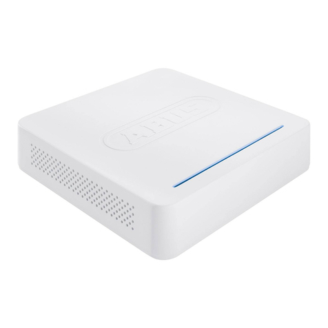
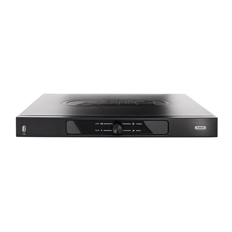
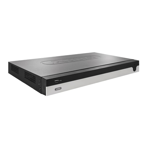
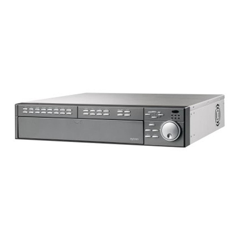
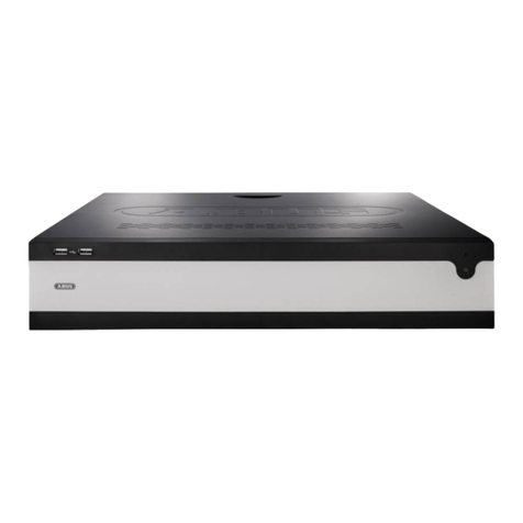
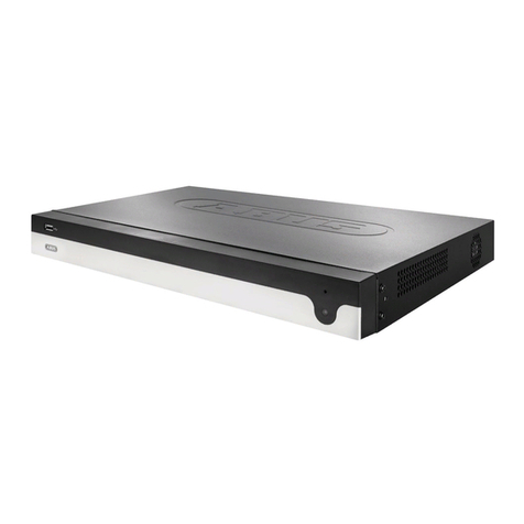
Abus NVR10010 User manual

ABUS embedded NVR
Web interface user manual
Date: 19.12.2019
Firmware: 4.x.x

This user manual contains important information on start-
ing operation and using the device.
Make sure that this user manual is handed over when the
product is given to other persons.
Keep this user manual to consult later.
You will find a list of contents with the corresponding
page numbers in the contents.

Contents
3
Important safety information ..........................................................................................................................................5
Explanation of symbols....................................................................................................................................................5
Intended use ....................................................................................................................................................................5
General ............................................................................................................................................................................5
Power supply ...................................................................................................................................................................5
Installation........................................................................................................................................................................6
Children............................................................................................................................................................................6
EU Directives ...................................................................................................................................................................6
Compatibility ....................................................................................................................................................................7
General ............................................................................................................................................................................7
Compatible recorders.......................................................................................................................................................7
Compatible browsers .......................................................................................................................................................7
Image display performance..............................................................................................................................................8
System requirements.......................................................................................................................................................8
Introduction......................................................................................................................................................................9
General information .........................................................................................................................................................9
Internal access (LAN) ......................................................................................................................................................9
Local interface.................................................................................................................................................................9
ABUS IP installer.............................................................................................................................................................9
Windows UPnP search....................................................................................................................................................9
External access (internet)..............................................................................................................................................10
Using IPv6.....................................................................................................................................................................10
Dual-Stack and Dual-Stack Lite (DS Lite).....................................................................................................................10
Setting up port forwarding (IPv4)...................................................................................................................................10
Setting up the ABUS server (IPv4)................................................................................................................................11
DDNS for IPv6 (IPv6) ....................................................................................................................................................11
Access to DS Lite connections (IPv6)...........................................................................................................................11
Logging in for the first time.............................................................................................................................................12
Live cast..........................................................................................................................................................................14
General information on live image.................................................................................................................................14
Live image function areas..............................................................................................................................................14
Using the menu bar........................................................................................................................................................14
Using the camera list .....................................................................................................................................................14
Using the action bar.......................................................................................................................................................15
Using the view bar .........................................................................................................................................................15
PTZ control menu ..........................................................................................................................................................16
Playback view.................................................................................................................................................................17
General information on playback...................................................................................................................................17
Playback function areas.................................................................................................................................................17
Using the archive list......................................................................................................................................................18
Using the view bar .........................................................................................................................................................18
Using the playback controls...........................................................................................................................................18
Using the action bar.......................................................................................................................................................18
Export functions.............................................................................................................................................................19
Download.......................................................................................................................................................................19
Using the timeline and calendar ....................................................................................................................................19
Image export...................................................................................................................................................................20
Image export..................................................................................................................................................................20
Settings...........................................................................................................................................................................21
General settings.............................................................................................................................................................21
Setting: Local .................................................................................................................................................................22
Contents
4
General information on local settings ............................................................................................................................22
Live cast parameters.....................................................................................................................................................22
Record file settings........................................................................................................................................................22
Image/clip settings.........................................................................................................................................................23
Setting: System..............................................................................................................................................................24
General information on system......................................................................................................................................24
System settings..............................................................................................................................................................24
Overview........................................................................................................................................................................24
Time settings.................................................................................................................................................................24
Output menu..................................................................................................................................................................25
Maintenance ..................................................................................................................................................................25
Upgrade and maintenance............................................................................................................................................25
Protocol .........................................................................................................................................................................25
Camera management....................................................................................................................................................25
Add manually.................................................................................................................................................................25
Quick add ......................................................................................................................................................................26
Custom protocol ............................................................................................................................................................26
Managing users .............................................................................................................................................................27
Fault rectification...........................................................................................................................................................28
Disposal..........................................................................................................................................................................28
Notes on EC directives for waste electrical and electronic equipment..........................................................................28
Notes on RoHS EU Directive.........................................................................................................................................28

Important safety information
5
Important safety information
Explanation of symbols
The following symbols are used in this manual and on the
device:
Symbol
Signal
word
Meaning
Warning
Indicates a risk of injury or health
hazards.
Warning
Indicates a risk of injury or health
hazards caused by electrical
voltage.
Important
Indicates possible damage to the
device/accessories.
Note
Indicates important information.
The following annotations are used in the text:
Meaning
1. …
2. …
Required action to be carried out in a set order
•…
•…
List without a set order, given either in the text
or warning notice
Intended use
Only use the recorder for the purpose for which it was
built and designed. Any other use is considered unin-
tended!
This device may only be used for the following pur-
pose(s):
•This recorder is used in combination with video signal
sources (network cameras) and video output devices
(TFT monitors) for property surveillance.
Note
Data storage is subject to national data privacy
guidelines.
When carrying out the installation advise your cus-
tomers of the existence of these guidelines.
General
Before using this recorder for the first time, please read
the following instructions carefully and observe all warn-
ing information, even if you are familiar with the use of
such recorders.
Warning
All guarantee claims are invalid in the event of
damage caused by non-compliance with this user
manual.
We cannot be held liable for resulting damage.
Warning
In the event of personal or material damage
caused by improper operation or non-compliance
with the safety information, we cannot be held lia-
ble.
All guarantee claims are void in such cases.
Retain this manual for future reference.
If you sell or pass on the recorder to third parties, you
must include these instructions with the device.
Power supply
Warning
Prevent data loss:
The recorder should only ever be used with a de-
vice that is constantly connected to an uninter-
ruptible power supply (UPS) with surge protection.
Warning
Modifications to the device invalidate the guaran-
tee.

Important safety information
6
Installation
•Observe all safety and operating instructions before
installing the device for the first time.
•Only open the housing to install the hard disk drive.
•Only install the software on devices that are ex-
pressly suitable for the intended purpose. Otherwise,
damage to the device can occur.
Note
Compatible devices:
- NVR10010
- NVR10020
- NVR10030
- NVR10040
- NVR10030P
- NVR10020P
Warning
If in doubt, have the device installed by a special-
ist technician rather than carrying it out yourself.
Children
•Keep electrical devices out of reach of children.
Never allow children to use electrical devices unsu-
pervised. Children may not always properly identify
possible hazards. Small parts may be fatal if swal-
lowed.
•Keep packaging film away from children. There is a
risk of suffocation.
•This device is not intended for children. If used incor-
rectly, parts under spring tension may fly out and
cause injury to children (e.g. to eyes).
EU Directives
This device complies with the requirements of the EU
Low Voltage Directive (2014/35/EU), the EMC Di-
rective (2014/30/EU) and the RoHS Directive
(2011/65/EU). The declaration of conformity can be
obtained from:
ABUS Security-Center GmbH & Co. KG
Linker Kreuthweg 5
86444 Affing
GERMANY
To ensure this condition is maintained and that safe oper-
ation is guaranteed, it is your obligation to observe this
user manual.
Please read the entire user manual carefully before put-
ting the product into operation, and pay attention to all
operating instructions and safety information.
All company names and product descriptions are trade-
marks of the corresponding owner. All rights reserved.
If you have any questions, please contact your specialist
installation contractor or specialist dealer.
Disclaimer
This user manual has been produced with the
greatest of care. Should you identify any omis-
sions or inaccuracies, please contact us at the ad-
dress shown on the back of the manual. ABUS
Security-Center GmbH does not accept any liabil-
ity for technical and typographical errors, and re-
serves the right to make changes to the product
and user manuals at any time and without prior
warning. ABUS Security-Center GmbH is not lia-
ble or responsible for direct or indirect damage re-
sulting from the equipment, performance and use
of this product. No guarantee is made for the con-
tents of this document.
Keep electrical devices out of reach of children. Never al-
low children to use electrical devices unsupervised.

Compatibility
7
Compatibility
General
This manual describes the use of the ABUS embedded
recorder via the integrated web server. Information on
compatible cameras and other components can be
found either in the basic manual (local interface) or on
the ABUS website.
When you first try to access the server on your
browser (on Windows), you will be prompted to install
a plug-in in order to use the web server. You will need
administrator rights on your PC to do this. Access to
the live images and recordings is only possible with the
plug-in installed.
Compatible recorders
Device type
Item number
NVR
NVR10010, NVR10020,
NVR10030, NVR10040,
NVR10050,NVR10020P,
NVR10030P
Compatible browsers
OS
Browser
Version
Windows
Internet Explorer
11 or higher
Windows
Firefox
49 or higher
MacOS
Safari
10 or higher
Due to strict guidelines, the following browsers do not
support the plug-in and are therefore not compatible:
•Edge (Microsoft)
Note
If you access the recorder web server using Safari
on MacOS, you will need to obtain the required
plug-in from the ABUS homepage
(http://www.abus.com). Search for the recorder
item number on the homepage and download the
plug-in from the item card in the "Downloads"
area.

Compatibility
8
Image display performance
To display network camera video streams (both live
images and playback of recordings)
on your PC via the browser, the digitally compressed
data must be transmitted from the recorder to your PC
and then "decrypted". This process will take up a differ-
ent amount of processing power on your PC depend-
ing on the camera resolution. The higher the resolution
and bit rate of the individual camera stream, the
greater the required processing power for the decryp-
tion process.
If the number of camera streams to be displayed ex-
ceeds the decoding power of the PC, the CPU usage
will reach 100% and operation will be slow. Should this
occur, reduce the number of cameras to be displayed
at the same time in live cast or playback view.
The recorder web interface provides the option of dis-
playing a sub-stream (generally 720p or smaller) for in-
dividual cameras in the live image to facilitate this. This
approach reduces the bandwidth and requires less
processing power for decryption on the PC.
In playback view, the cameras are played back in the
corresponding quality of the recording (main stream).
Depending on the application and camera type, this
may mean that not all cameras can be displayed at
once. Split the cameras into different views to work
around this limitation.
System requirements
Use up-to-date PC hardware (no older than two years)
in order to ensure the smooth operation of the software
in combination with cameras and the recorder. The re-
quirements for your PC system increase with the num-
ber of camera channels, as well as with the related
video resolution and bit rate of the cameras. The cam-
era display (resolution, bit rate and number of chan-
nels) strongly depends on the software functions used
(live image display, playback, time of analysis).
Warning
Check your PC's CPU usage when displaying live
streams or playing back recorded data using the
Task Manager (on Windows).
CPU usage < 100%
Select sub-stream

Introduction
9
Introduction
General information
This manual describes the use of the ABUS embedded
recorder via the web interface using a web browser on a
remote PC on the network.
For this purpose the recorder must already by integrated
in your network in order to facilitate access via a PC. In
simple cases, both the PC and the recorder are located
on the same local network.
Note
Ensure that the recorder is connected directly to
your CCTV network (switch) via a network cable.
For optimal performance do not use a Wi-Fi con-
nection between the recorder and the CCTV net-
work.
Internal access (LAN)
The recorder is accessed by typing the IP address in the
navigation bar of the browser.
The following describes several different options for how
to determine the current IP address of your recorder in
order to access it via the local network.
Local interface
Open the overview menu on the recorder's local interface
and note the IP address.
ABUS IP installer
Install the ABUS IP installer (Windows) on your PC and
start the program. The program searches your local net-
work for ABUS network products.
Use the full-text search to filter result lists with lots of en-
tries by specific item numbers. Then double-click on the
list entry for your product to directly open the recorder
web interface.
Windows UPnP search
Open the network search using the "network" icon in the
Windows File Explorer. All devices on your network that
were detected via UPnP are displayed here. Since the re-
corder supports this network service, you can open the
web interface directly by double-clicking on the icon with
the item number in the label field (e.g. NVR10040).
192.168.0.5
192.168.0.4
IP address
Double-click on search result
Full-text search
Network
Double-click on
recorder icon

Introduction
10
External access (internet)
The recorder can also be accessed externally by typing
the IP address in the browser’s navigation bar. Since the
recorder is generally not accessible directly from the in-
ternet, you must set up port forwarding on your router.
Accordingly, the router IP address must be entered as
the IP address in the navigation bar when accessing the
recorder via the internet (IPv4). Additional settings are
required for IPv6, which are described in detail below.
The network services on the recorder do not have to be
adapted for access to the web interface on the local net-
work. For external access, you may have to adjust the
default settings of the ports in order to enable access.
The following points are important for remote access:
•Notes on using IPv6
•Setting up port forwarding on your router
•Required ports for remote access to the web in-
terface: HTTP(S) and RTSP
•Free DDNS service from ABUS: ABUS server
•Access to DS Lite connections
Using IPv6
Modern internet providers switch what is known as "Dual-
Stack" internet access to the customer's landline connec-
tion. This means that the router provides access to the
internet via both the IPv4 protocol and IPv6. The ABUS
embedded recorder supports both protocols as standard.
Since IP communication for remote connections takes
place between two end points, both subscribers (re-
corder and receiving point) must use the same communi-
cation protocol in order to successfully establish a con-
nection. The IPv6 protocol is not currently widely availa-
ble, so pure IPv6 communication is not practical for the
moment, especially if the receiving point (e.g. the web
browser on a laptop) is mobile and may switch between
IPv4 and IPv6 networks.
Note
As of 2016/2017: IPv6 is currently undergoing
global "roll-out". This means that increasingly
more providers are allowing for IPv6 access to the
internet. Check your internet connection, both on
the recorder and on the intended receiving points,
to take potential limitations and instructions for the
operation of the recorder into account ahead of
time.
We provide the following tips and instructions for setting
up external access to the ABUS embedded recorder,
which take both protocols into account.
Dual-Stack and Dual-Stack Lite (DS Lite)
As part of the global roll-out of IPv6, the IANA stipulated
that internet providers which use IPv6 must also allow
their customers to access the internet via IPv4, in order
to be able to access internet servers/services that are
only available on the IPv4 network. Since the global IPv4
address pool has already been used up, internet provid-
ers that do not have enough ipV4 addresses use an al-
ternative technology known as "Dual-Stack Lite".
Note
Internet connections with "Dual-Stack Lite" have
significant limitations when using IPv4. If possible,
use a provider that employs actual Dual-Stack
technology or ask your provider whether your
Dual-Stack Lite access can be changed to a real
Dual-Stack connection.
Based on the fact that IPv6 is not available everywhere,
we recommend establishing your remote connection via
IPv4 (even with Dual-Stack connections). This particu-
larly applies to mobile networks, which are still in the
process of completely switching to IPv6 on end devices,
with a few exceptions (as of 2016/2017).
Setting up port forwarding (IPv4)
In order for the recorder (web interface) to be accessible
via the internet, the network service ports of the recorder
must be able to be accessed externally using port for-
warding on the router. Set up 1:1 port forwarding on the
router, which opens the HTTP(S) port of the recorder as
well as the RTSP port on the WAN connection of the
router.
Setup differs depending on your router's model. Refer to
the router manufacturer's instructions to find out how to
set up port forwarding on your router.
The rule should be structured according to the fol-
lowing scheme (example):
External HTTP port (on the router): 80
External HTTPS port (on the router): 443
External RTSP port (on the router): 554
Forward to target address:
192.168.0.5 (local IP address of your recorder)

Introduction
11
Internal HTTP port (on the recorder): 80
Internal HTTPS port (on the recorder): 443
Internal RTSP port (on the recorder): 554
Your router's IP address, which is displayed on the WAN
interface, is used as the external IP address.
To open the recorder's web interface via remote connec-
tion, enter the following URL in the navigation bar of the
browser:
http://external-router-IP:80
https://external-router-IP:443
The externally forwarded RTSP port is automatically
used by the web interface and does not have to be spec-
ified again.
Note
We recommend changing the default ports for port
forwarding in order to avoid an overlap with other
services (for example, port 443 is likely to be the
same port used by the web interface of the router
for external access). This also makes it easier to
set up forwarding for other devices later.
Setting up the ABUS server (IPv4)
Internet providers generally disconnect the internet con-
nection of the router for a few seconds every day. During
this process, the router is assigned a new IP address.
This means that for remote access to the web interface
of the recorder, the new valid IP address of the router
(WAN interface) has to be used.
In order to avoid having to check this address on a daily
basis, ABUS offers a free DDNS service: the ABUS
server. With this service, the router's external IP address
is assigned a host name on the server, which is matched
with the current IP and port information on a regular ba-
sis.
Access to the recorder web interface then takes place
via the ABUS server host name:
http://meinrekorder.u21783.abus-server.com:1500
Go to https://www.abus-server.com to register for free
and set up your recorder.
The ABUS server only supports IPv4 addresses.
Instructions on how to set up your recorder for the ABUS
server are stored in the downloads area for the recorder
on http://www.abus.com.
DDNS for IPv6 (IPv6)
The supported DDNS providers for the ABUS embedded
recorder currently only allow for IPv4 DDNS synchronisa-
tion. Another service is currently required to run DDNS
synchronisation for IPv6. Because, unlike with IPv4,
every device (recorder) with IPv6 receives a unique
global IP address, the current IPv6 address of the re-
corder must be transmitted to the DDNS provider when
using DDNS for IPv6.
You can do this via your router, for example, if your
router supports this type of service.
AVM/Fritzbox/MyFritz recommendation:
The "MyFritz" service can detect all global IPv6 ad-
dresses of connected devices and provide them via the
MyFritz service as a DDNS host name.
Note
Network service ports (HTTP(S) and RTSP) must
be opened to use the web interface on the re-
corder with IPv6 as well.
Access to DS Lite connections (IPv6)
Many internet providers use DS Lite to switch their cus-
tomers' connections to IPv6 access. With DS Lite your
router does not have full IPv4 access to the internet. The
IPv4 address that is assigned to the router is segmented
by what is known as a "CGN" (Carrier Grate NAT). This
means that an additional NAT is directly connected by
the provider for IPv4. As a result, NAT configuration (port
forwarding) for IPv4 is no longer possible on the local
router and therefore incoming IPv4 queries are discarded
directly at the provider end (CGN). It is then no longer
possible to access your local devices externally via IPv4.
Its is highly likely, however, that remote access to your
recorder's web interface will take place on an IPv4 net-
work (receiving point). Additional services must be used
to allow external access in such cases.

Introduction
12
Static-Access.NET/Portmapper/FIP-Box recommen-
dation:
The "Static-Access.NET" service makes it possible to
convert IPv4 data packets from an IPv4 network (receiv-
ing point) into IPv6 packets. These IPv6 packets can then
be provided to the recorder via normal port transfers on
the router. Further details on this can be found at
http://www.static-access.net/.
Logging in for the first time
Once access to the recorder web interface has been es-
tablished, you will see the login screen on the browser.
Log in for the first time by entering your user name and
password and indicating your desired system language.
If a notification for the plug-in download appears, this
means that the recorder plug-in is not yet installed on
your PC and must first be downloaded and installed be-
fore you can proceed.
Note
You must have local administrator rights on your
PC to install the plug-in. Ensure that you have
these before starting the installation.
Open file "ABUS Rekorder Web-Plugin.exe" to start the
installation. Once the plug-in is installed, the web inter-
face and all of its functions can be used.
Note
The plug-in contains the video decryption software
for displaying live streams on your web browser.
Subsequent firmware updates may mean that the
plug-in also needs to be updated on your PC in fu-
ture. The web interface may then prompt you to
re-install the plug-in.
Plug-in download
Plug-in installation

Introduction
13
ABUS LINK STATION
The ABUS Link Station service enables quick and easy
remote access, e.g. via a mobile end device (without port
forwarding).
Note: An Internet connection is essential for using this
service.
You can add devices in the “ABUS Link Station” app very
easily by scanning the QR code of the device. This QR
code is included in the scope of delivery or you can use
the QR code displayed here in the menu.
Activate
Tick the box to enable this service.
After activation, a menu for entering
the “Verification code” and agreeing
to the conditions of use will appear.
Stream en-
cryption
Here you can enable encryption of
the data transmission.
Register-
Status
Shows whether the recorder is con-
nected to the ABUS Link Station ser-
vice

Live cast
14
Live cast
General information on live image
Live cast starts automatically once you have logged into
the web interface. The live image function provides the
option of displaying live images and executing camera
commands for all cameras connected to the recorder.
This is the core function of the recorder, in addition to
playback.
Double-clicking an image displays the selected camera
image in full screen or switches back to the original view.
Live image function areas
The live cast view is divided into the following function ar-
eas:
Using the menu bar
The following options are available:
Using the camera list
The camera list contains all cameras connected to the re-
corder. Double-clicking a camera name displays the cor-
responding camera in the live image.
Parameter
Description
Menu bar
Global display of the configuration
and control menus
Camera list
Select from the connected cam-
eras for live cast
Action bar
Control camera commands and
carry out actions for the selected
camera (red frame)
View bar
Configure multi-view and stream-
ing options
PTZ control
Control menu for PT(Z) cameras
Parameter
Description
Activates the live image view (live
cast)
Changes to playback view
Changes to snapshot view
Changes to system settings
Action bar
Menu bar
PTZ control
View bar
Camera list
Logout

Live cast
15
To display the camera at a specific position in the live im-
age (multi-view), proceed as follows:
1. Select the position in the live cast (red frame).
2. Double-click the desired camera in the camera
list.
3. The camera is displayed at the desired position.
The following functions/status displays are available in
the camera list:
The default setting for manual stream selection is "1".
This means that the high-resolution "main stream" of the
camera is displayed. This is the best option in most
cases. It is only practical to adjust the manual stream se-
lection if there is a risk of a performance bottleneck dur-
ing transmission:
•If you wish to display lots of cameras at the same
time (nine or more), the processing power of your
PC may not be sufficient to decode all video
streams. Change the setting to sub-stream "2".
•If you are accessing the web interface via the in-
ternet and wish to display multiple cameras at the
same time, the upload of the receiving point must
be of a sufficient size. At the same time, the
download on the receiver side must also provide
sufficient bandwidth. Change the setting to sub-
stream "2" if one of the two sides does not have
enough bandwidth.
•If you are intentionally accessing the recorder via
the internet with very low bandwidth, you can ac-
tivate transcoded stream "3" to request an image
transfer with very low resolution and bit rate (e.g.
QCIF/64 Kbit). The selected video stream is then
scaled down by the recorder.
Using the action bar
(1) (2) (3) (4) (5) (6) (7) (8)
No.
Meaning of the symbol
(1)
Stop all active camera live streams. Start all cam-
era live streams at the same time.
(2)
Create a snapshot of the selected camera (red
frame)
(3)
Create a manual data export (video clip)
(4)
Activate the e-PTZ function (depends on camera)
(5)
Previous live cast view (function depends on se-
lected view 1x1, 2x2, 3x3, etc.)
(6)
Next live cast view (function depends on selected
view 1x1, 2x2, 3x3, etc.)
(7)
Activate audio for selected camera (red frame)
and adjust the volume
(8)
Activate full-screen mode (exit with ESC)
Using the view bar
(1) (2) (3)
No.
Meaning of the symbol
(1)
Configure the live cast panel distribution (number
of cameras which can displayed at the same
time).
(2)
Select the live cast stream type to be used for all
cameras simultaneously.
Parameter
Description
Displays the recorder name
Live cast display for camera is ac-
tive (blue) or deactivated (grey)
Create a manual data export
(video clip)
Manually select the video stream
of the desired camera. Hover the
mouse cursor over the symbol to
select the desired stream. The
configuration for main/sub/trans-
coded streams can be adjusted in
the settings under "Audio & video"
in the "Stream type" section.

16
(3)
Select the audio output of the recorder for two-way
audio control via the web interface.
This function is only available if a microphone and
speaker are connected to your PC while you have
the live cast open.
1 = RCA audio output 1
2 = RCA audio output 2
PTZ control menu
The actions of all buttons in the PTZ control menu, plus
presets/patrols, are always applied to the camera cur-
rently selected (red frame). Depending on the camera
model, not all functions may be available.
Parameter
Description
PTZ con-
trol
Move the camera in the desired direc-
tion using the buttons. Manually ad-
just the zoom , focus
and iris . The
button activates the horizontal scan.
Special
com-
mands
Open the camera menu (if availa-
ble)
3D zoom (zoom in/out to a drawn
screen)
Centring mode
Speed
Speed at which the cameras are man-
ually moved to positions
Preset
Navigate to tab to carry out preset
positions. Up to 256 present positions
can be accessed/stored from here
(depending on the camera model).
a) Move the camera to the desired po-
sition.
b) Select a list entry and press .
The current camera position is as-
signed to the selected preset.
c) Press to access a stored pre-
set. The camera then moves to the
previously stored position.
Patrol
Navigate to tab to carry out pa-
trols. Up to four patrols can be ac-
cessed/stored from here.
a) Start a patrol with . The patrol re-
mains active until another PTZ com-
mand is sent to the camera or the pa-
trol is stopped manually with .
b) Program a patrol with . Enter the
preset positions, speed and hold time.
c) Delete the content of a patrol with
Special com-
mands
PTZ control
Presets
Patrols

Playback view
17
Playback view
General information on playback
Playback allows recorded video data from cameras on
the recorder to be played. The data is played in the qual-
ity at which it was recorded as configured in the network
camera settings.
Note
Adjust the camera quality settings in the menu un-
der "Settings →Audio & video" accordingly. Gen-
erally the "main stream" of the camera on the re-
corder is recorded.
Double-clicking an image displays the selected camera
image in full screen or switches back to the original view.
Playback function areas
The playback view is divided into the following function
areas:
Parameter
Description
Menu bar
Global display of the configuration
and control menus
Archive list
Select from the recorded cameras
for playback on the web interface
View bar
Configure multi-view options
Timeline
Display the recorded data in the
time stream and select the play-
back time (time tracker)
Playback
controls
Control playback for the selected
camera archive
Action bar
Control camera commands and
carry out actions for the selected
camera (red frame)
Calendar
Select the playback date
Playback stream
View bar
Timeline
Action bar
Calen-
dar
Archive list
Time tracker
Logout
Menu bar
Playback controls

Playback view
18
Using the archive list
The archive list contains the recordings of all cameras
connected to the recorder. Double-clicking an archive
name displays the corresponding camera archive in the
playback view and plays it directly.
To display the camera archive at a specific position on
the screen (multi-view), proceed as follows:
1. Select the position in the playback view (red
frame).
2. Double-click the desired camera archive in the
archive list.
3. The image is displayed at the desired position.
Using the view bar
Configure the playback panel distribution (number of
camera archives which can displayed at the same time).
Note
The more camera archives playing at the same
time, the more data that is transferred via the net-
work. Since the data is generally always recorded
in the best possible quality, this may result in a
large upload for a remote connection.
Using the playback controls
The playback controls are the core element of playback.
The basic functions for playing recorded data are pro-
vided here.
Using the action bar
(1) (2) (3) (4) (5) (6) (7)
No.
Meaning of the symbol
(1)
Stop all active playback
(2)
Create a snapshot of the selected camera (red
frame)
(3)
Create a manual data export (video clip)
First, click the symbol to set the start time for the
export. Click again to set the end time. A video clip
file is then exported to your PC. The length of the
clip is based on the duration of the played data.
Ac-
tion
Meaning of the symbol
Reverse play
Forward play
Stop
Go forward in slow-motion (8x →1x)
Fast forward (1x →8x)
Pause
Single frame play
Activate transcoded playback.
Set the resolution, bit rate and frame rate
here.
When this function is activated, the recorder
scales down the recorded video material in
real time to suit a lower resolution/bit
rate/frame rate. Click the icon again to stop
transcoded playback for the selected camera.

Playback view
19
(4)
Activate the e-PTZ function (depends on camera)
(5)
Activate audio for selected camera (red frame)
and adjust the volume
(6)
Download the recorded data from the recorder
(7)
Activate full-screen mode for the active camera
(red frame –exit with ESC)
Export functions
If snapshots or video clips are created from running play-
back, this data is stored in the user-specified directory on
your PC. You can manually change this path in the web
interface settings.
The default path for exported files is:
C:\Users\[USERNAME]\Web\
[USERNAME] is the name of the Windows user under
which the web interface is run.
Note
You can freely change the settings for the export
path under "Settings →Local".
Download
A new window opens when the download function is acti-
vated on the action bar. You can download the stored
video data from the recorder hard disk drive directly to
your PC from here. Select one or more files and click the
"Download" button to start the data transfer.
Under the default setting, continuous recordings are
stored in 1 GB blocks on the recorder. If the scene you
wish to access is in one of these blocks, the entire file
must be downloaded. Event recordings are stored in
smaller blocks (corresponding to the duration of the event
in question).
Using the timeline and calendar
The most important control element on the timeline is the
time tracker. The time tracker indicates the current time
of playback. Move the timeline with the mouse using the
drag and drop function to change the playback time.
The recordings are displayed as coloured bars on the
timeline. The colour coding is explained below:
The default setting for the timeline display is 24 hours.
This means that recordings for the entire day are dis-
played. The timeline can be made smaller or larger using
the button, in order to play back targeted time
ranges in the current day.
The days are selected using the calendar. The colour
coding for calendar days is explained below:
Colour
Meaning
Continuous recording
Event recording (motion, alarm input,
VCA)
Command (not currently in use)
Manual recording
Colour
Meaning
Currently selected day (blue text). The
current day has at least one recording
(red corner).
Day is not selected (black text), but
does have at least one recording (red
corner).
Day is not selected and has no record-
ings.
Time tracker
Zoom
Recordings
Select data
Define filters
Start download
Calendar

Image export
20
Image export
Image export
You can download the stored snapshot data from the re-
corder hard disk drive directly to your PC from here. Se-
lect one or more files and click the "Download" button to
start the data transfer.
There are several filter options available to narrow down
the result list of image files:
•Channel number (camera selection)
•File type (event selection)
•Start time
•End time
The default path for exported files is:
C:\Users\[USERNAME]\Web\
[USERNAME] is the name of the Windows user under
which the web interface is run.
Note
You can freely change the settings for the export
path under "Settings →Local".
Click on the "Live cast" button to display a preview of the
snapshot file.
Start download
Menu bar
Logout
Define filters
Select data
Other manuals for NVR10010
1
This manual suits for next models
6
Table of contents
Other Abus DVR manuals

Abus
Abus Eyton TV8925 User manual

Abus
Abus NVR10020P User manual

Abus
Abus TVVR30003 User manual

Abus
Abus TVVR45020 User manual

Abus
Abus TVVR25000 User manual

Abus
Abus TVVR60011 User manual

Abus
Abus TVVR33005 User manual

Abus
Abus TVHD80120 User manual

Abus
Abus TVVR36401 User manual

Abus
Abus Eytron TV8931 User manual