Eddystone Short Wave User manual
ULT&' E
amil-0 TtJE PHCNE
THE,:)rdmary broadcast side of wireless on
the medium and long waves under existing
circumstances, has :ost much of its early appeal
.. .to the real radio enthusiast. This is due to the range
of these wavelengths being limited and the general
reception conditions a known quantity.
Short wave radio, on the other hand, offers the
World as a field for Nception with that unknown
factor, the ether, to add to the thrill of the game.
Further, on the ultra short waves, which are coming
into greater prominence and exists a whole
Held for t-4titiine experiment at present comparatively
unexplored.
We hope that this third number of the Eddystone
Short Wave Manual will prove of help and interest to
those who wish to join the ranks of radio enthusiasts
who find this the most interesting side of wireless.
Stratton & Co. Ltd.,
Eddystone Works.
Bromsgrove Street.
BIRNANGHANI 5
aft

(VoJ
EDDYSTONE
SHORT WAVE MANUAL
CONTENTS Pages
The All World Two 2 to 7
The "Everyman" Short Waver 8 to 11
Short Wave Aerials 12 to 14
5 Valve A.C. Short Wave Superheterodyne Receiver 15 to 19
Self Modulating Oscillator 20
A Four Band Transmitter . . 21 to 23
5 Valve Short Wave Super -Heterodyne Receiver, Battery Model 24 to 27
Ultra Short Wave Radio Telephone ..28 to 32
A Modulated Oscillator 33
One Valve Short Wave High Frequency Amplifier or Short Wave
Converter 34 to 38
Solder Your Wireless Set 39
Two Valve Transceiver 40 & 41
Absorption Waveme ter 42
Wavelength or Frequency 42
Valve Bases 413
Short Wave Broadcast Stations 44
COPYRIGHT BY STRATTON & CO.. LTD.. BIRMINGHAM 5.

2EDDYSTONE SHORT WAVE MANUAL
THE ALL WORLD TWO
15.5 TO 52 METRES.
A POWERFUL 2 VALVE SHORT WAVE BATTERY RECEIVER
WITH BANDSPREAD TUNING.
The set has a smart
front appearance ----
The Eddystone All World Two receiver
is designed to give adequate world wide head-
phone reception with a minimum expenditure.
It is the outcome of considerable research in
our laboratory and during extensive tests
results were highly satisfactory ; America,
Australia and other long distant stations being
consistently received with good volume and
quality.The set is inexpensive and easy to build ;
simple to operate and has small current
consumption. It is equally suitable for short
wave broadcast or amateur band reception
since it is fitted with the special Eddystone
Bandspread Tuning unit, which allows contin-
uous bandspreading on all wavebands. The
waverange covered by the two coils supplied
with the receiver is 15 to 52 metres, but if it is
wished to receive on intermediate bands
between 50 and 200 metres, extra coils are
available and no structural or wiring alterations
necessary.
There is a high degree of sensitivity com-
bined with low noise level, and careful design
of the aerial input circuit has completely
eliminated tuning blind spots. Constant and
smooth reaction has negligible effect on tuning
and complete stability of handling is assured.
A rigid die-cast chassis houses the component
parts and provides ample screening.
The theoretical circuit embodies a screened
H.F. Pentode valve followed by an audio
stage which can use either triode or pentode
valve as desired. The aerial input circuit,
although simple in design, was only satis-
factorily developed after protracted experi-
ments on many different types of aerials.
It ensures complete freedom from tuning
blind spots, thus saving the extra cost of an
H.F. stage which is the generally accepted
medium for overcoming such trouble. Re-
generation is obtained by a modified Reinartz
circuit, feedback current being controlled by
varying the S.G. voltage with a potentiometer.
The high tension battery is suitably isolated
to prevent current leakage through the
potential divider circuit.
CONSTRUCTION.
Proceed as follows :
The sockets for the aerial and earth and
'phone strips should be mounted and the strips
finally screwed on the back of the chassis by
the " 6BA roundhead screws provided.
All holes in the chassis marked " E " on
the practical wiring diagram must be carefully
scraped above and below the chassis as earth
connections are made at these points.
Mount the 1+1 mfd. condenser on the
front of the chassis with countersunk screws,
and fix the two valveholders and coil base in
position. Do not forget the soldering tags "E"
under some of the fixing screws.
The reaction trimmer is now mounted in
its appropriate fixing holes. The reaction
potentiometer, on -off switch and tank con-
denser should be assembled on the chassis,
the panel and 0-10 scales fitted, and the panel
held in position by the switch, condenser and
potentiometer fixing nuts.
To ensure absolutely noiseless reaction
control the specified variable potentiometer
should be used.
and a tidy,
attractive chassis lay out.
EDDYSTONE SHORT WAVE MANUAL
ALL WORLD TWO-continued
The tank condenser spindle should be
turned until the moving plates are fully out
of mesh with the fixed plates and the pointer
knob fixed opposite the 0 division on the scale
by screwing up the small grub screw. By
turning the knob clockwise, the condenser
will rotate in 10 steps up to the maximum
capacity.
Turn the reaction spindle as far anti-
clockwise as it will go, and fix the pointer
knob so that the pointer is placed at the posi-
tion which the small hand of a clock points
to at eight o'clock. :
It is advisable to leave the tuning con-
denser off the panel until all the wiring is
finished. This enables the chassis to be
mounted upside down on the edge of a table
to facilitate wiring. Wires Nos. 9 and 10 may
be connected at one end, but the free ends
left until the rest of the wiring is completed.
Certain condenser and resistances not
already assembled are automatically supported
by their connections, so the wiring may now
be commenced, and should be carried out
without difficulty with the aid of the wiring
plan on centre pages and point to point
connection list on pages 4 and 5 overleaf.
VALVES.
The kit has been designed around the
Mullard SP2 Screened Grid andllazOa`sP32.9
Triode valves. The constructor may use any
of the two other triode valves specified or
alternatively one of the three pentode valves
listed below.
The average total number of milliamps
for any of the pentodes or triodes are given in
the right-hand column below, from which
it will be seen that the use of the pentode type
of output does not increase the consumption
of the receiver, but does in practice consider-
ably add to the signal strength.
A five -pin valveholder is fitted in the
output stage, the centre pin automatically
connecting the auxiliary grid to the H.T.
supply when a pentode is used.
An automatic bias resistance. is incorpor-
ated in this receiver, and it has been dalculated
to be equally suitable for the following output
valves : Total_ Milli -
(a) (b) amps with
TRIODE PENTODE Detector Valve
VALVE (7;-) VALVE (13/6) (a) (b)
Mazda P220 Mazda Pen. 220 4.5 4.8
Osram LP2 Osram PT2 4.55 5.1
Mullard PM2A Mullard PI1122A 4.55 3.95
RESISTANCE COLOUR CODE.
Resistance Body Tip Dot
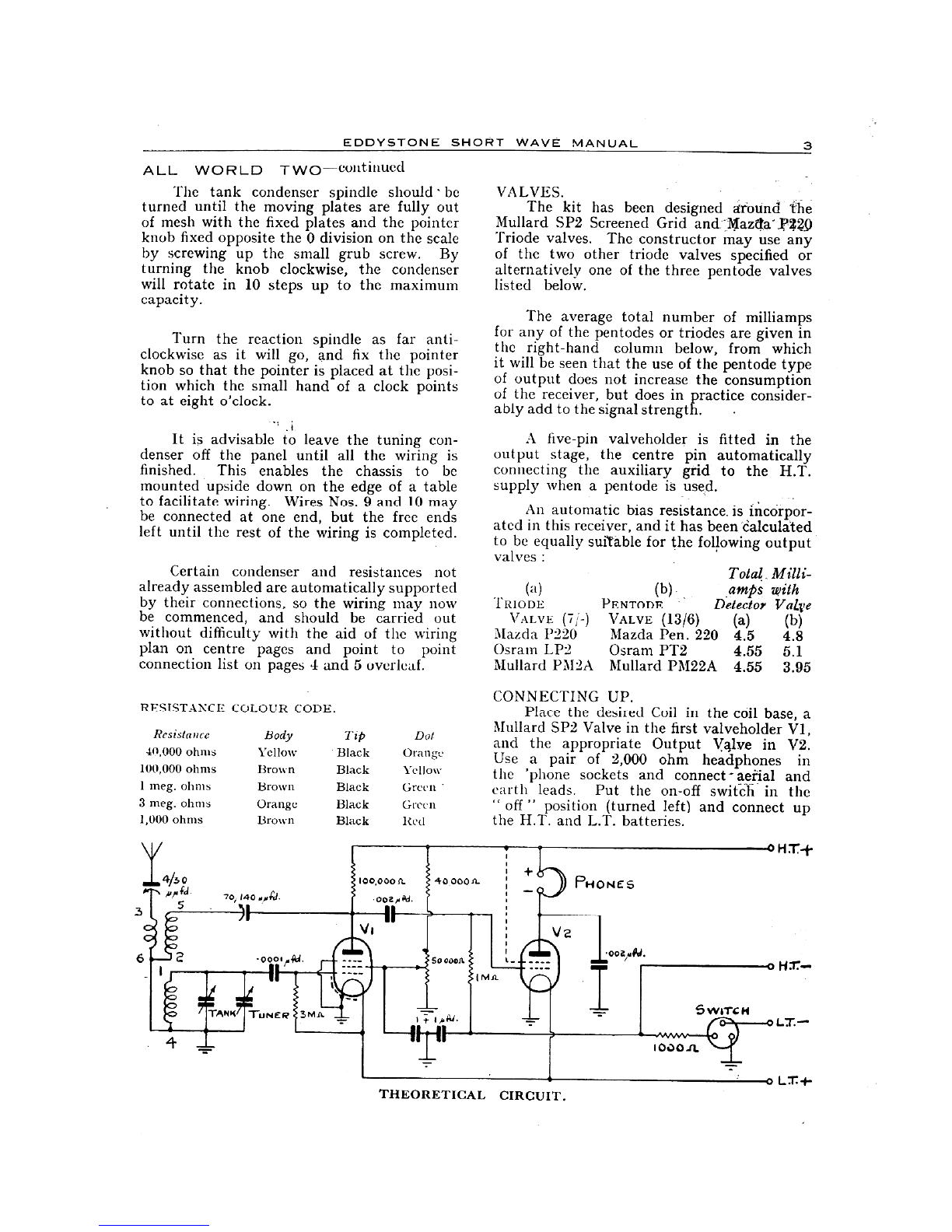
CONNECTING UP.
Place the desired Coil in the coil base, a
Mullard SP2 Valve in the first valveholder V1,
and the appropriate Output VAlve in V2.
40,000 ohms Yellow Black Orange Use a pair of 2,000 ohm headphones in
100,000 ohms Brown Black Yellow the 'phone sockets and connect.- aerial and
I meg. ohms Brown Black Green earth leads. Put the on -off switch in the
3 meg. ohms Orange Black Green " off " position (turned left) and connect up
1,000 ohms Brown Black Red the H.T. and L.T. batteries.
V.4150
570, 140 sofq
000 W.
TUNER
100,000 CA.
002,a0d.
IF
V I
40 00011.
THEORETICAL CIRCUIT.
PHONES
1ooapPd.
I
H:r+
000
SWITCH
o H77.-
LT.-
o LT. 4-
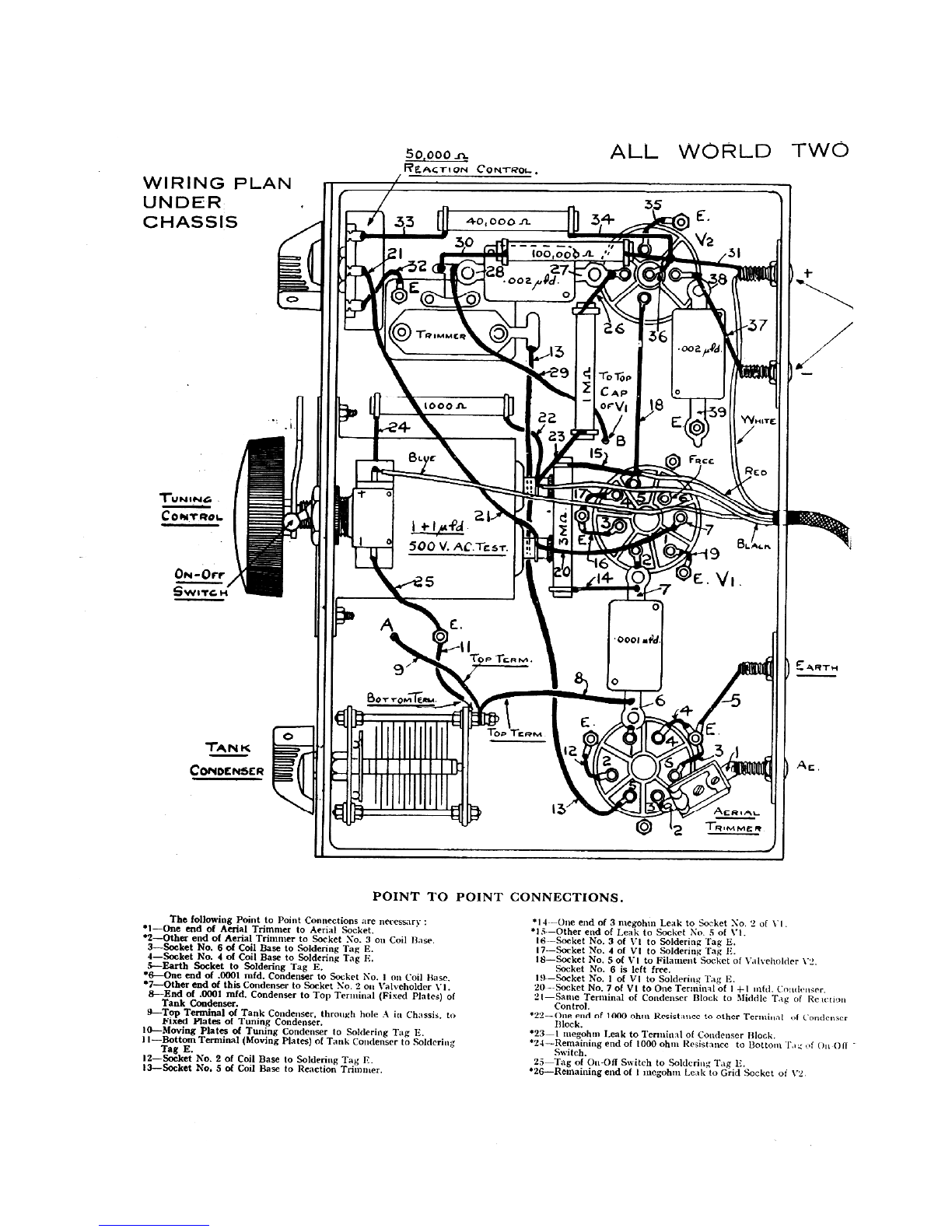
WIRING PLAN
UNDER
CHASSIS
TUNING
CONTROL
ON -Orr
Gwvrc.
TAN K
CONDENSER
50,000 SI-
REACTION CONTROL.. ALL WORLD TWO
313 40,000 .fL41-
To IMMCR
E.
TERM.TOP
F. I*
POINT TO
Too -re R 1,4
10 Top
C AP
orVi
0001 add
POINT CONNECTIONS.
The following Point to Point Connections arc necessary :
1-One end of Aerial Trimmer to Aerial Socket.
. 2-Other end of Aerial Trimmer to Socket No. 3 on Coil Base.
3-Socket No. 6 of Coil Base to Soldering Tag E.
4-Socket No. 4 of Coil Base to Soldering Tag E.
5-Earth Socket to Soldering Tag E.
6-One end of .0001 mfd. Condenser to Socket No. 1 on Coil Base.
7-Other end of this Condenser to Socket No. 2 011 'alveholder VI.
8-End of .0001 mfd. Condenser to Top Terminal (Fixed Plates) of
Tank Condenser.
9-Top Terminal of Tank Condenser, through hole A in Chassis, to
Fixed Plates of Tuning Condenser.
10-Moving Plates of Tuning Condenser to Soldering Tag E.
11-Bottom Terminal (Moving Plates) of Tank Condenser to Soldering
Tag E.
12-Socket No. 2 of Coil Base to Soldering Tag E.
I3-Socket No. 5 of Coil Base to Reaction Trimmer.
ARTe4
AERIAL
1-OiNtINICe
14 ---One end of 3 megohin Leak to Socket No. 2 of Vt.
15 --Other end of Leak to Socket No. 5 of VI.
16 --Socket No. 3 of VI to Soldering Tag E.
17 --Socket No. 4 of VI to Soldering Tag E.
18-Socket No. 5 of VI to Filament Socket of Valveholder V2.
Socket No. 6 is left free.
19 -Socket No. 1 of VI to Soldering Tag E.
20 --Socket No. 7 of VI to One Terminal of I 4-1 mid. Condenser.
21-Same Terminal of Condenser Block to Middle Tag of Rc u.tion
Control.
'22 --One end of 1000 ohm Resistance to other Terminal of Condenser
Block.
* 23-1 megohin Leak to Terminal of Condenser Block.
'24 ---Remaining end of 1000 ohm Resistance to Bottom T, f On -Off -
Switch.
25 --Tag of Ott -Off Switch to Soldering Tag E.
. 26-Remaining end of I megohnt Leak to Grid Socket of V2.
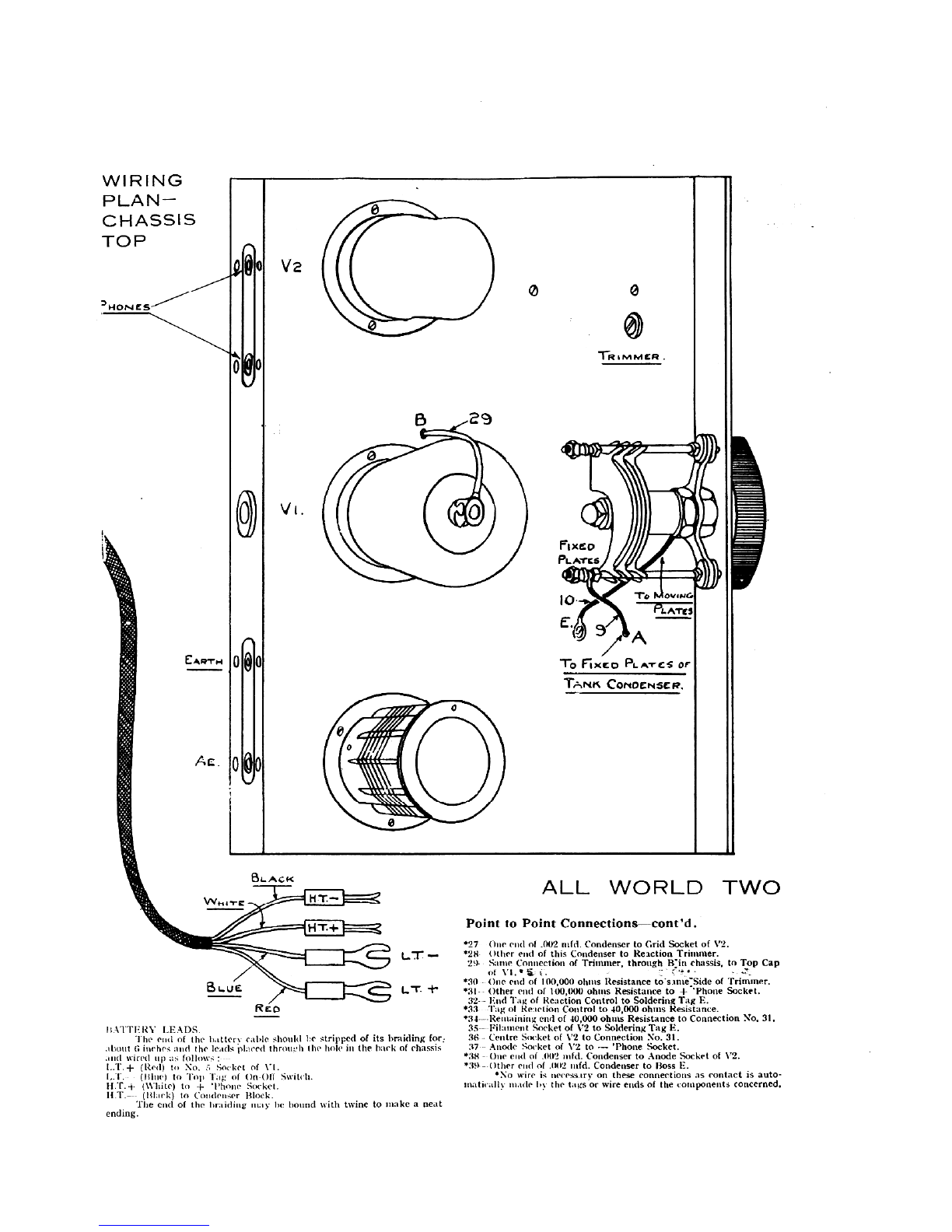
WIRING
PLAN-
CHASSIS
TOP
ON ES
CART0-4
Ac. 0
V2
0
EILAcK
RED
0
0
L7r
L'r
0
ItATTERY LEADS.
The end of the battery cable should be stripped of its braiding for:
about G inches and the leads Placed through the hole in the hack of chassis
and wired up :is follows :
LT.+ (Rod) to No. Socket of VI.
LT. (nine) to Top Tag of OrtOff Switch.
11.T. (White) to A-- 'Phone Socket.
11.T.-- (Black) to Condenser Block.
The end of the braiding tuay be bound with twine to make a neat
ending.
29
00
T -R ?AMER .
FIxeo
PL Arcs
10 To OViNG
L-77.071re,
To FIXED PL A -rcS or
Conoemscp.
ALL WORLD TWO
Point to Point Connections-cont'd.
*'27 One end of .002 infd. Condenser to Grid Socket of V2.
.28. Other end of this Condenser to Reaction Trimmer.
20 Same Connection of Trimmer, through B'in chassis, to Top Cap
of
*30 One end of 100,000 ohms Resistance to-same:Side of Trimmer.
* 31- Other end of 100,00(1 ohms Resistance to + 'Phone Socket.
:32. - End Tag of Reaction Control to Soldering Tag E.
.33 Tag of Reaction Control to 40,000 ohms Resistance.
34- -Remaining end of 40,000 ohms Resistance to Connection No. 31.
3,5-- Filament Socket of V2 to Soldering Tag E.
36 Centre Socket of V2 to Connection No. 31.
37 Anode Socket of 1'2 to -- 'Phone Socket.
. 3t3 - One end of .002 infd. Condenser to Anode Socket of 1'2.
*:39 Other end of .002 infd. Condenser to Floss E.
No wire is necessary on these connections as contact is auto-
matically made by the tags or wire ends of the components concerned.
.6 EDDYSTONE SHORT WAVE MANUAL
ALL WORLD
OPERATION.
Unscrew aerial trimmer to nearly mini-
mum capacity and put tuning dial at 0°
and the tank condenser at position 0. Switch
on by turt*ig the switch to the right, and
adjust reaction trimmer until a faint rushing.
sound is hard in the 'phones when the
reaction control is turned three-quarters of
the way clockwise. It will generally be found
that the reaction trimmer has to be screwed
fully clockWise for correct oscillation. Stations
may now be tuned in. Leaving the tank
condenser at 0, turn the tuning dial from
0 to 100 degrees, keeping the set just off
the verge of oscillation for telephony and
weakly oscillating for 'GMT. signals. Stations
will now4e heard. Turn tank condenser
to No. lliositio'n and again tune from 0
to 100: deg*ees; and so on until the whole
10 positions of the tank condenser have been
explorftd; -The receiver should not be calibrated
until the optitnium setting of the aerial
trimmer has been found. Proceed likewise
with other. coil.
TWO-continued
For the best results with any aerial, the
aerial trimmer screw should be turned half
a turn clockwise at a time until a blind spot
is found on one of the two coils. Then reduce
the setting of this condenser until the blind
spot disappears. This position will give maxi-
mum selectivity ,and sensitivity. In short,
use as much capacity as possible for the aerial
trimmer, consistent with freedom from blind
spots. The set may now be calibrated, but
the aerial trimmer should not be re -adjusted
again since this would alter calibrations.
.;
To achieve maximum efficiency however,
alarger value condenser (our Catalogue
No. 1013 being quite suitable) may be used
in place of the aerial trimmer. Blind spots
may be prestnt but can usually be moved to
a part of the band which does not matter. If
this alteration is made the wave range charts
on page 7 will not apply.
If no signals are heard, check the receiver
with a milliammeter and a voltmeter. The
following voltages and currents should obtain
with 115 volt H.T. supply :
SP2-Anode Current (approx.) 0.25 m.a.
knode Voltage 90 volts.
P220-Anode Current 3 m.a.
Anode Voltage 115 volts.
Potentiometer Current 1.25 m.a.
Total Current 4.5 m.a. at 115 volts.
These figures are for an average kit and
will vary slightly for individual receivers.
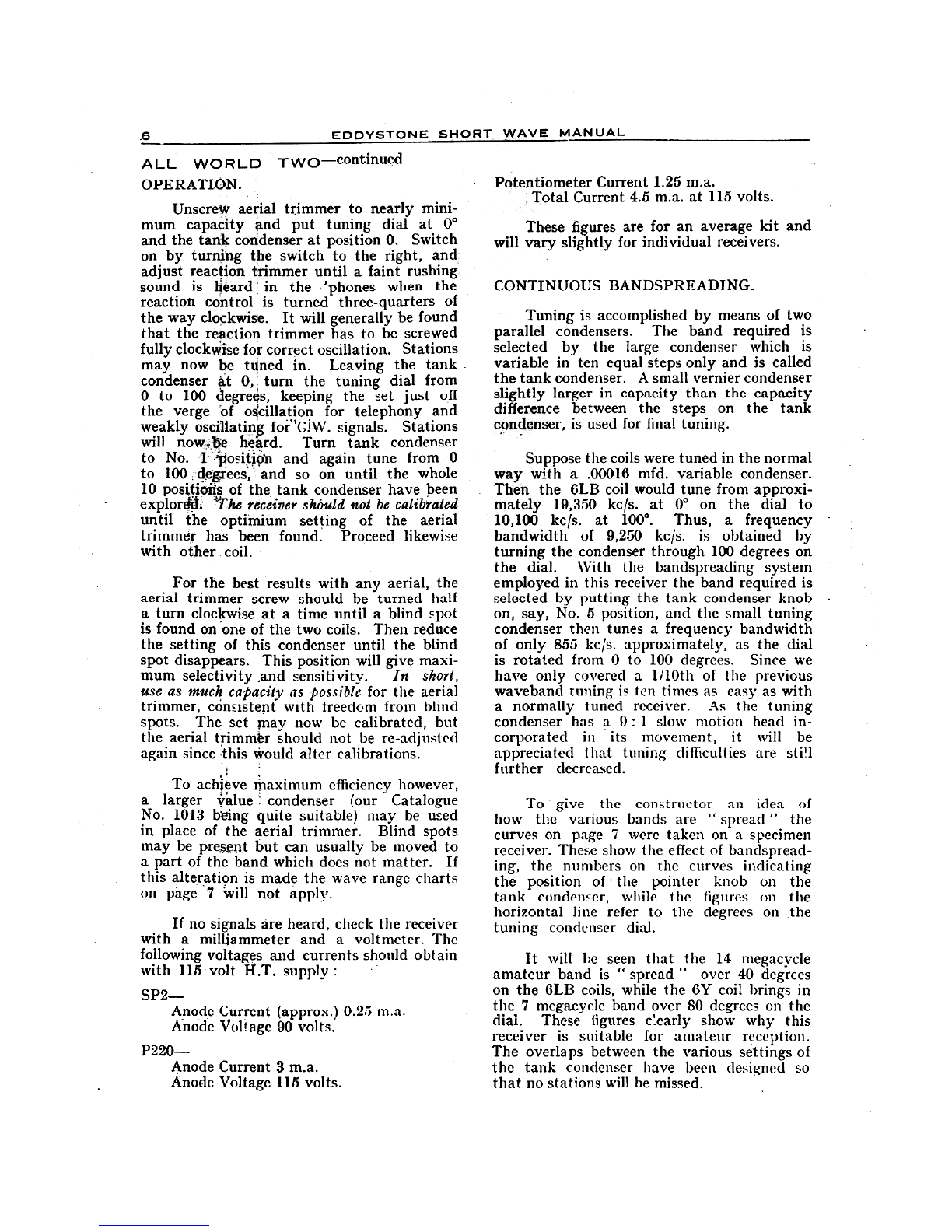
CONTINUOUS BANDSPREADING.
Tuning is accomplished by means of two
parallel condensers. The band required is
selected by the large condenser which is
variable in ten equal steps only and is called
the tank condenser. A small vernier condenser
slightly larger in capacity than the capacity
difference between the steps on the tank
condenser, is used for final tuning.
Suppose the coils were tuned in the normal
way with a .00016 mfd. variable condenser.
Then the 6LB coil would tune from approxi-
mately 19,350 kc/s. at 0° on the dial to
10,100 kc/s. at 100°. Thus, a frequency
bandwidth of 9,250 kc/s. is obtained by
turning the condenser through 100 degrees on
the dial. With the bandspreading system
employed in this receiver the band required is
selected by putting the tank condenser knob
on, say, No. 5 position, and the small tuning
condenser then tunes a frequency bandwidth
of only 855 kc/s. approximately, as the dial
is rotated from 0 to 100 degrees. Since we
have only covered a 1/10th of the previous
waveband tuning is ten times as easy as with
a normally tuned receiver. As the tuning
condenser has a 9 : 1slow motion head in-
corporated in its movement, it will be
appreciated that tuning difficulties are stig
further decreased.
To give the constructor an idea of
how the various bands are " spread " the
curves on page 7 were taken on a specimen
receiver. These show the effect of bandspread-
ing, the numbers on the curves indicating
the position of the pointer knob on the
tank condenser, while the figures on the
horizontal line refer to the degrees on .the
tuning condenser dial.
It will be seen that the 14 megacycle
amateur band is " spread " over 40 degrees
on the 6LB coils, while the 6Y coil brings in
the 7 megacycle band over SO degrees on the
dial. These figures c!early show why this
receiver is suitable for amateur reception.
The overlaps between the various settings of
the tank condenser have been designed so
that no stations will be missed.

EDDYSTONE SHORT WAVE MANUAL 7
ALL WORLD TWO-continued
COIL 6LB.
2 0000
19,000
8,000
,-;i 7,000
16,000
15,000
14.0o0
3 15,000.
L12,000
11,000
oosmo
RANGE.
O
a3456
9t
O'50' 100'
TUNING CellOiNSER SCALE.
Waverange : 19,350 Kc/s - 10.100 Kc/s.
(I Sm.-29-7m.)
I Z,000
61,000
Z 10,000
9.000
8.000
7 .000
it. c.000
5.000
NOTE:
Com 6Y.
RANGE.
0
6810
50' 100°
TUNING CONDENSER SCALE.
Waverange 11..350 Kc/s-5.6S0 Kc/s.
(26'45m.-527 m.)
It must be emphasised that the curves
shown are for an average receiver and are
drawn to give the listener some know-
ledge of the wavelengths covered by each
position of the tank condenser. In-
dividual receivers will vary somewhat,_
due to different valve and circuit capaci-
ties, and the effect of aerial load,
although minimised in this receiver, will
influence the wavelengths covered to a
small degree.
AS S.W. ADAPTOR.
This receiver provides an efficient
alternative to the super -het type of short wave
converter. Its output can easily be connected
to the pickup terminals of a broadcast receiver
by a 1-1 transformer.
EDDYSTONE PARTS.
1 6 -pin Low Loss Coil, type 6LB Price
16 -pin Low Loss Coil, type 6Y .. 4/-
1 Patented Tank Condenser with Knob and
Graduated Dial Plate, Cat. No. 1042 6/-
1 Bandspread Condenser Unit with Slow
Motion Head, Knob, Dial and Cursor,
Cat. No. 1043 6/6
1 Short Wave Mica Trimmer Condenser, Cat.
No. 1023 .. 1/-
1 Low Loss Valveholder, Cat. No. 954 1/-
1 Low Loss Valveholder, Cat. No. 964 1/3
1 Low Loss Valveholder, Cat. No. 985 1/4
11 x 1 mfd. Fixed Condenser 4/-
1 Aluminium Die -Cast Chassis, drilled all
necessary holes, finished inside and
out battleship grey cellulose 12/9
1 Burr Walnut Bakelite Panel, drilled neces-
sary holes .. 2/9
2 Bakelite Terminal Panels .. 6d.
1 Scale and Pointer Knob, 11" dial 1/-
1 Special 50,000 ohm Variable Potentiometer 5/-
1 Welded Steel Cabinet, finished dark crystal-
line brown, Cat. No. 1061 9/6
MISCELLANEOUS PARTS.
170/140 m.mfd. Trimmer Condenser
13 -point Switch
2 Dubilier Condensers, .002 mfd.
1 Dubilier Condenser, .0001 mfd.
1 Erie Resistor, 1,000 ohms, 1 watt
1 Erie Resistor, 40,000 ohms, 1 watt
1 Erie Resistor, 100,000 ohms, 1 watt
1 Erie Resistor, 3 megohm, 1 watt
1Erie Resistor, 1 megohm, 1 watt
Length 4 -way Cable ..
4 Clix Parallel Plugs and Sockets (2 red and
2 black)
1pair Clix Spades, red and black
1pair Clix Wander Plugs, red and black
Valves. Mullard SP2
Output valve as detailed in instructions
(Triode or Pentode).
Connecting Wire, Screws, Tags, Nuts, Thimble
Clip, etc. ..
Approximate Total Cost of Complete Kit, 67/6
(less valves).
ADDITION OF H.F. AMPLIFIER.
The performance of the All World Two
can at any time be extended by the use of the
H.F. amplifier unit described on page 34.
In this case the output of the amplifier should
be connected to end 1 of the grid coil in the
All World Two. If a common battery supply
is used, note special remarks in H.F. amplifier
article, otherwise automatic G.B. of All World
Two will be shorted.

EDDYSTONE SHORT WAVE MANUAL
THE "EVERYMAN" SHORT WAVER
A 4 -VALVE BATTERY RECEIVER WITH BANDSPREAD TUNING.
1 5 - 1 00 METRES.
Here is a specially designed short wave
receiver which is simple to construct and
relatively inexpensive. An ideal set capable
of giving loud speaker results that will satisfy
the ardent short wave enthusiast.
The circuit has been based on that of the
Eddystone " Kilodyne Four," a set which
has already achieved a world-wide reputation
for performance and reliability. The patented
method of bandspread tuning makes the
receiver easy to handle and facilitates the
thrill of world-wide reception on the short
wave bands. The circuit consists of a high
frequency amplifier, detector and two low
frequency stages. It is free from " blind
spots " or hand capacity, and has smooth
and gentle reaction control. The set does not
re -radiate and can be used without any inter-
ference to the general domestic receiver.
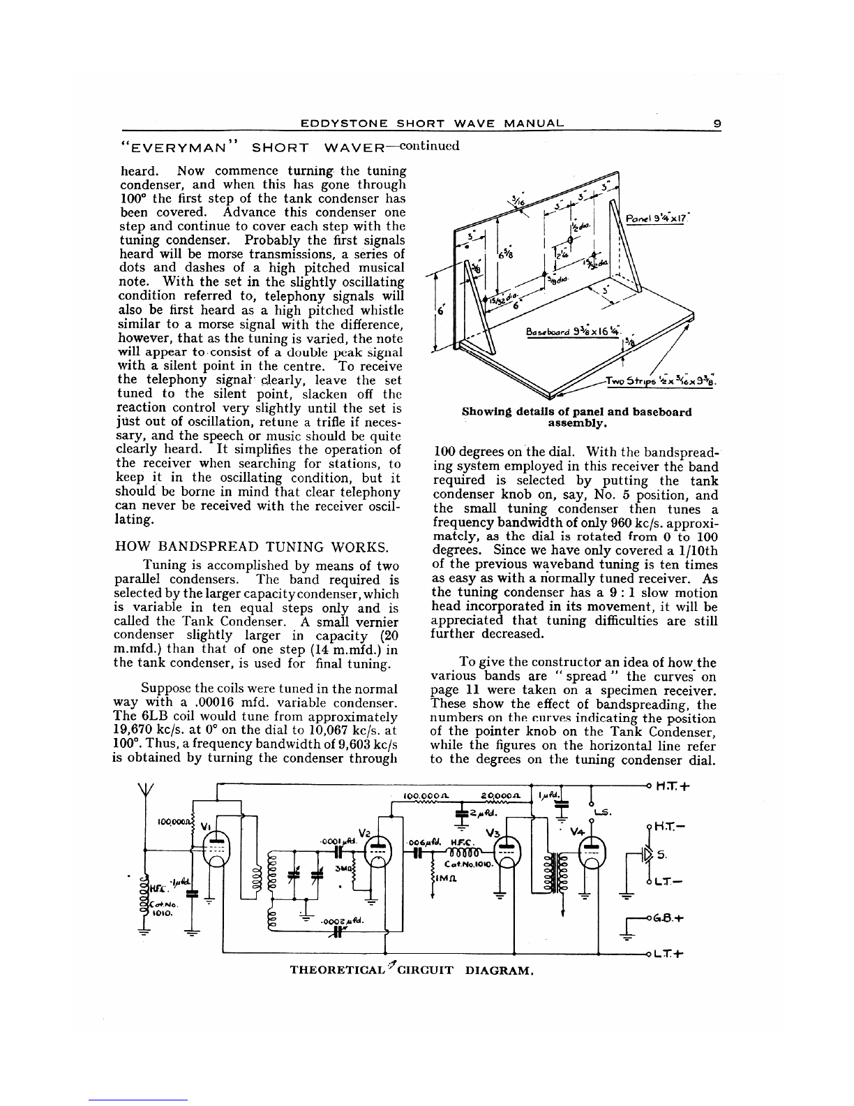
CONSTRUCTION.
The wiring plan and point to point con-
nection details make this quite straightforward.
It is best to proceed as follows :-
Make up panel and baseboard as shown
in sketch on page opposite. Only simple
tools are needed and plywood will be most
suitable. The chassis or panel can, of course,
be polished to suit individual choice. A
metal panel is not recommended, it may cause
hand capacity. The assembly comes next ;
but first for ease of wiring, it will be advan-
tageous to tin or give the connecting points
a coat of solder before parts are fixed in place.
Lay out components as shown in wiring
plan and proceed to fasten them down.
It should be noted that the coil base and valve-
holder of V2 are mounted on insulating pillars.
When fixing variable condensers to panel
take care to bed down squarely otherwise
pointer may foul panel.
Make sure in the wiring that all joints arc
strongly made. One poor or high resistance
joint can adversely affect the set's performance,
or alternatively may give the set a very high
background noise level whith is most unde-
sirable.
Baseboard view showing general lay out
of components.
BATTERIES.
A 2-irolt low-tension is needed, the Exide
D.F.G. or larger capacity being suitable.
High-tension should be a minimum of 120 volts.
This can, with some advantage to quality, be
increased to 150 volts. The grid bias battery
should be 4i volts. G.B. - 1 from the 1 meg.
leak goes to the 1volt tapping, G.B. - 2
from the transformer to 3 or 44 volts according
to anode voltage used. L.T. current is .55
amperes and H.T. 12. m/a at 120 volts. On
the battery leads there are two spade con-
nections to L.T. battery and two wander
plugs for H.T. battery.
TRYING OUT AND OPERATING
THE SET.
Insert a coil, and then starting with both
tuning, tank, and reaction condenser at
minimum, switch on the receiver. Increase
the reaction control slowly by means of the
vernier knob until at a certain point the set
will begin to oscillate ; this will be noticeable
immediately, since a low " rushing " sound
will be heard. Throughout the whole tuning
operations, this reaction control should be so
adjusted that the set is always only just in the
oscillating condition. The reaction control
should never be turned any more than is
ticessary for the first reaction sound to be
EDDYSTONE SHORT WAVE MANUAL 9
"EVERYMAN" SHORT WAVER-continued
heard. Now commence turning. the tuning
condenser, and when this has gone through
100° the first step of the tank condenser has
been covered. Advance this condenser one
step and continue to cover each step with the
tuning condenser. Probably the first signals
heard will be morse transmissions, a series of
dots and dashes of a high pitched musical
note. With the set in the slightly oscillating
condition referred to, telephony signals will
also be first heard as a high pitched whistle
similar to a morse signal with the difference,
however, that as the tuning is varied, the note
will appear to consist of a double peak signal
with a silent point in the centre. To receive
the telephony signal- clearly, leave the set
tuned to the silent point, slacken off the
reaction control very slightly until the set is
just out of oscillation, retune a trifle if neces-
sary, and the speech or music should be quite
clearly heard. It simplifies the operation of
the receiver when searching for stations, to
keep it in the oscillating condition, but it
should be borne in mind that clear telephony
can never be received with the receiver oscil-
lating.
HOW BANDSPREAD TUNING WORKS.
Tuning is accomplished by means of two
parallel condensers. The band required is
selected by the larger capacity condenser, which
is variable in ten equal steps only and is
called the Tank Condenser. A small vernier
condenser slightly larger in capacity (20
m.mfd.) than that of one step (14 m.mfd.) in
the tank condenser, is used for final tuning.
Suppose the coils were tuned in the normal
way with a .00016 mfd. variable condenser.
The 6LB coil would tune from approximately
19,670 kc/s. at 0° on the dial to 10,067 kc/s. at
100°. Thus, a frequency bandwidth of 9,603 kc/s
is obtained by turning the condenser through
Two Strips x 31e: x 94;.
Showing details of panel and baseboard
assembly.
100 degrees on .the dial. With the bandspread-
ing system employed in this receiver the band
required is selected by putting the tank
condenser knob on, say, No. 5 position, and
the small tuning condenser then tunes a
frequency bandwidth of only 960 kc/s. approxi-
mately, as the dial is rotated from 0 to 100
degrees. Since we have only covered a 1/10th
of the previous waveband tuning is ten times
as easy as with a normally tuned receiver. As
the tuning condenser has a 9 : 1 slow motion
head incorporated in its movement, it will be
appreciated that tuning difficulties are still
further decreased.
To give the constructor an idea of how_the
various bands are " spread " the curves on
page 11 were taken on a specimen receiver.
These show the effect of bandspreading, the
numbers on the curves indicating the position
of the pointer knob on the Tank Condenser,
while the figures on the horizontal line refer
to the degrees on the tuning condenser dial.
THEORETICAL 'CIRCUIT DIAGRAM.
0 H T. -I-
H T. -
LT.-
,

10 EDDYSTONE SHORT WAVE MANUAL
"EVERYMAN" SHORT WAVER-continued
WIRING PLAN
Ac. EARTH.
27 24- 25
28 6.
TANK CON O.
22
ToBOTTOM
rERMINAr-
TUNING
c-c.
BLOC LT.-
RED LT.+
BLACK H T-
BROWN H T +
z00004
2Mro.
Z 50 V . AC Avocts.g.
Mir REACTION COND.
POINT TO POINT
1-Earth Terminal to F ncg. of V4.
2-Aerial Terminal to G of VI.
3-Earth Terminal to F neg. of VI.
4-Wire No. 1 to F neg. of V2.
5-Wire No. 1 to F neg. of V3.
6-F + of VI to F + of V2.
'7-F + of V2 to F -I-- of V3.
8-No. 6 of Coil Holder Socket to Plate Terminal
of Transformer.
9-Plate Terminal of Transformer to L.S. neg.
Terminal.
10-L.S. -I- Terminal to " P " of V4.
11-L.S. neg. Terminal to 1 mfd. Condenser.
12-" P " of V3 to H.T. -I- of Transformer.
13-F of V3 to F + of V4.
14-G. of V4 to GRID of Transformer.
15-On-Off Switch to 2 mfd. Condenser.
16-2 mfd. Condenser to 1 mfd. Condenser.
17-Wire No. 1 to Wire No. 16.
18-No. 2 Socket of Coil Holder to Fixed Plates of
Reaction Condenser.
19-No. 5 Socket of Coil Holder to " P " of V2.
20-Fixed Plates of Tuning Condenser to Fixed Plates
of Tank Condenser.
21-Moving Plates of Reaction Condenser to Moving
Plates of Tuning Condenser.
22-Moving Plates of Tuning Condenser to Moving
Plates of Tank Condenser.
23-Moving Plates of Tank Condenser to No. 4 Socket
of Coil Holder.
24-No. 4 Socket of Coil Holder to F ncg. of VI.
CONNECTIONS.
L.S. -
9
'YON-0rr SWiTC11.
25-No. 1 Socket of Coil Holder to Fixed Plates of
Tuning Condenser.
26-H.F. Choke across Aerial and Earth Terminal.
27-100,000 ohm Resistance :-Frcm No. 6 Socket of
Coil Holder to " P " of VI.
28-One End of .1 mfd. Condenser to " P " of V I.
Other End to " F " neg. of VI.
29-One End of .0001 mfd. Condenser to No. 1 Socket
of Coil Holder. Other End to " G " of V2.
30-One End of 3 meg. Resistance to " F " neg. of V2.
Other End to " G " of V2.
31-One End of H.F. Choke to " G " of V3.
32-Other End of H.F. Choke to .006 mfd. Condenser.
Other End of .006 Condenser to " P " of V2.
33-100,000 ohm Resistance to " P " of V2. Other
End to 2 mfd. Condenser.
34-One End of 20,000 ohm Resistance to 2 mfd.
Condenser. Other End to 1 mfd. Condenser.
35-Solder G.B. neg. 1 Lead to One End of 1meg.
Resistance.
36-Other End of 1 meg. Resistance to junction of
H.F. Choke and .006 Condenser.
37-G.B. neg. 2 Lead to G.B. Terminal of Transformer.
38-G.B. + Lead to On -Oft Switch.
39-Lead from No. 3 Socket on Coil Base to Top
Terminal of S.G. Valve.
40-Black Lead of 4 -way Battery Cable to On -Off
Switch.
41-Blue Lead of 4 -way Battery Cable to On -Oft
Switch.
42-Red Lcad of 4 -way Battery Cable to No. 13 Wire.
43-Brown Lead of 4 -way Batt( ry Cable to No. 8 Wire.
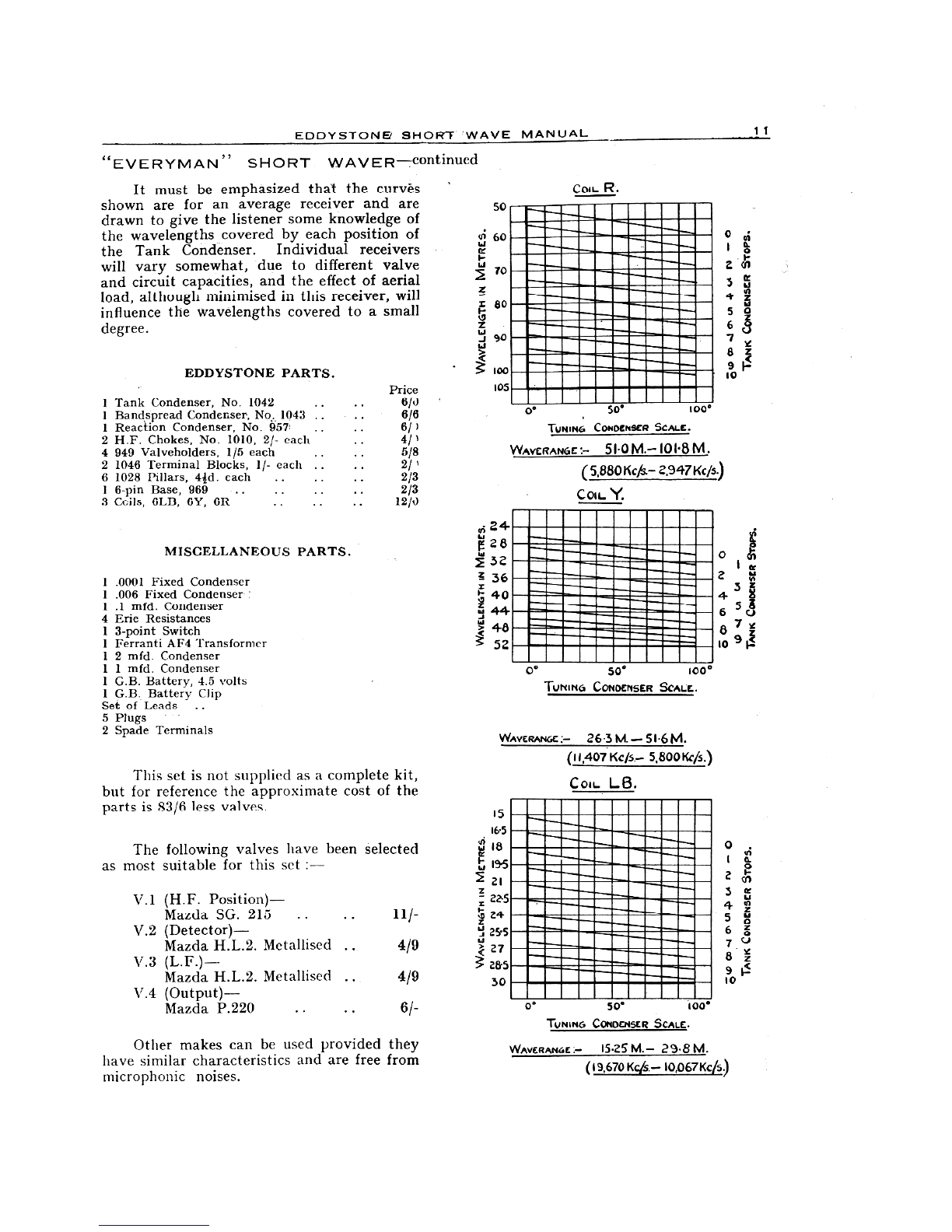
EDDYSTONe SHORT WAVE MANUAL 1i
"EVERYMAN" SHORT WAVER-continued
It must be emphasized that the curves
shown are for an average receiver and are
drawn to give the listener some knowledge of
the wavelengths covered by each position of
the Tank Condenser. Individual receivers
will vary somewhat, due to different valve
and circuit capacities, and the effect of aerial
load, although minimised in this receiver, will
influence the wavelengths covered to a small
degree.
EDDYSTONE PARTS. Price
1 Tank Condenser, No. 1042 .. 6/0
1 Bandspread Condenser, No. 1043 .. 6/6
1 Reaction Condenser, No. 957 .. 6/ )
2 H.F. Chokes, No. 1010, 2/- each 4/1
4 949 Valveholders, 1/5 each 5/8
2 1046 Terminal Blocks, 1/- each 2/1
6 1028 Pillars, 44d. each .. 2/3
16 -pin Base, 969 .. .. 2/3
3 Coils, 6LB, 6Y, 6R .. 12/0
MISCELLANEOUS PARTS.
1.0001 Fixed Condenser
1.006 Fixed Condenser
1.1 mfd. Condenser
4 Erie Resistances
13 -point Switch
IFerranti AF4 Transformer
12 mfd. Condenser
11 mfd. Condenser
1G.B. Battery, 4.5 volts
1 G.B. Battery Clip
Set of Leads ..
5 Plugs
2 Spade Terminals
This set is not supplied as a complete kit,
but for reference the approximate cost of the
parts is 83/6 less valves.
The following valves have been selected
as most suitable for this set :-
V.1 (H.F. Position)-
Mazda SG. 215 .11/-
V.2 (Detector)-
Mazda H.L.2. Metallised 4/9
V.3 (L.F.)-
Mazda H.L.2. Metallised 4/9
V.4 (Output)-
Mazda P.220 .6/ -
Other makes can be used provided they
have similar characteristics and are free from
inicrophonic noises.
50
fr; 60
cc210
zX 80z90
5- 100
105
24'2832?- 36
01- 4044tj 4852
Com. R.
5tew
S50667zz9 I-10
SO° 100°
TUNIN6 CONDENSER SCALE.
WAVERAN6E 51.0 M.- 101.8 M.
( 5,880 Itc/s.- 2,947 KC/5)
Con.. Y.
0° 50° 1000
TUNING CONDENSER SCALE.
WAVERANGE :- 263 M. - SI6 M.
(11,407 Kc/s- 5,800 Ws.)
COIL L6.
15
16-5
trikJ 18
reI- 19.5
21
225
0 24255272&530
0° 50° 100*
0
24
87 t
3
io 9
0In
Ia.
4.)"
3Lc
4- 2521,
6g
789'-10
TUNING CONDENSER SCALE.
WAVERAN6E 15.25 M.- 29.8M.
(19.670 Kcjs - 10,067K45)
12 EDDYSTONE SHORT WAVE MANUAL
SHORT WAVE AERIALS
An -efficient short wave aerial should have
the following characteristics :-
(a) Good pick-up
(b) High signal to noise ratio.
(c) Resonate on certain desired fre-
quencies and be semi-aperiodic on
other frequencies.
(d) Its impedance must be matched to
the input impedance of the receiver.
PICK-UP.
The first condition is easily attainable
provided high conductivity copper wire is
used in the installation and the aerial is erected
in a position where dielectric losses are at a
minimum, well away from buildings and
trees and particularly metal objects, such as
drainpipes; gutters, metal roofs, and telephone
or power lines. Since the current induced in
an aerial: is- directly proportional to the
effective height of the latter it is essential to
erect the aerial as high as - circumstances
permit.
HIGH SIGNAL/NOISE RATIO.
The signal to noise ratio is one of the most
important factors to be considered in the
design of an aerial. Due to thermal agitation,
shot and Johnson noise, there is always a
considerable amount of noise present in a
radio receiver, and it is a problem to reduce
this to a minimum-. It is in the first stage
that these effects are troublesome since the
noise level developed is amplified by each
succeeding valve. Therefore, no radio signal
of less intensity than this noise level will be
reproduced in the loud speaker and if the
strength of the weak signals can be increased
before they reach the receiver input then many
more stations will be heard.
In practice the strength of the weak signals
is increased by the use of resonant aerials,
and the, man-made static present in densely
populated areas is reduced by using transposed
lead-in wires.
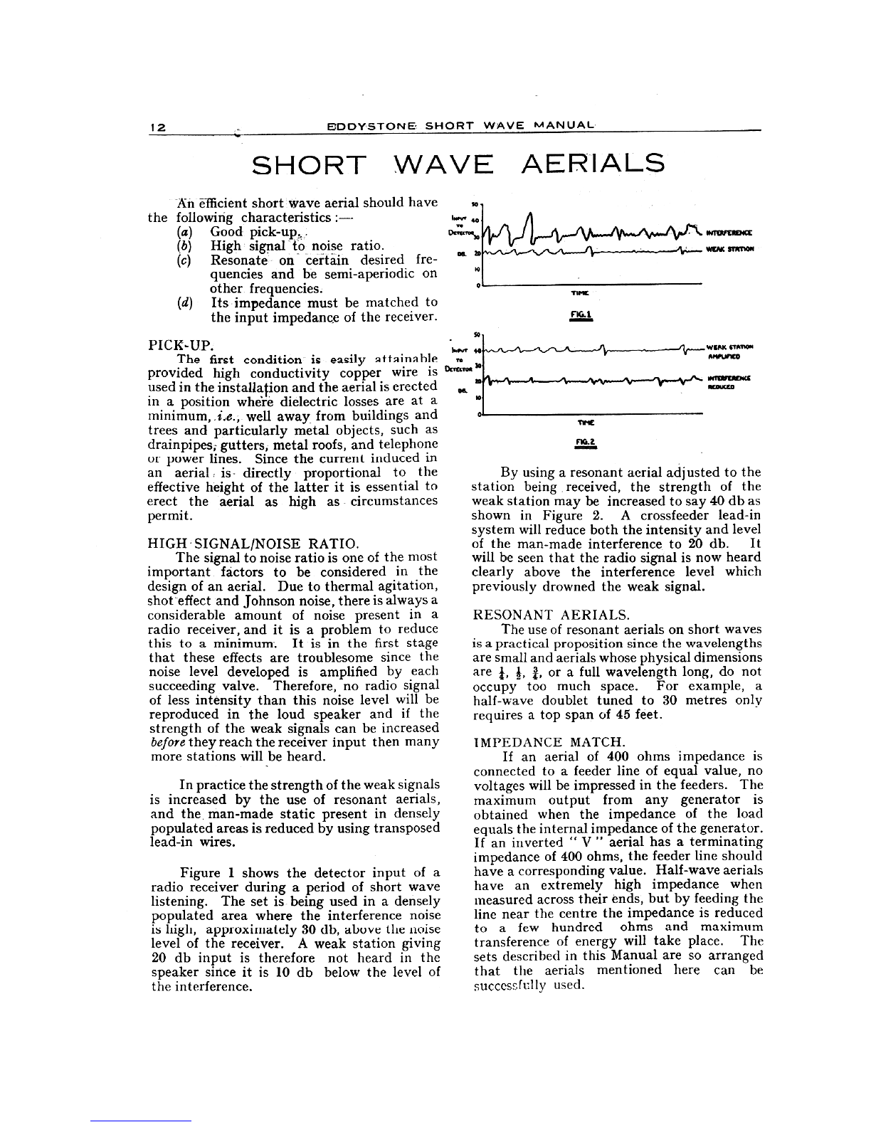
Figure 1 shows the detector input of a
radio receiver during a period of short wave
listening. The set is being used in a densely
populated area where the interference noise
is high, approximately 30 db, above the noise
level of the receiver. A weak station giving
20 db input is therefore not heard in the
speaker since it is 10 db below the level of
the interference.
so
Ipdftrr 44
To
Ocrecroo 30
TIME
FIG.1
nG.a
W11101 PAWN
411111.411:0
ofinfirellaKI
o
By using a resonant aerial adjusted to the
station being received, the strength of the
weak station may be increased to say 40 db as
shown in Figure 2. A crossfeeder lead-in
system will reduce both the intensity and level
of the man-made interference to 20 db. It
will be seen that the radio signal is now heard
clearly above the interference level which
previously drowned the weak signal.
RESONANT AERIALS.
The use of resonant aerials on short waves
is a practical proposition since the wavelengths
are small and aerials whose physical dimensions
are f, or a full wavelength long, do not
occupy too much space. For example, a
half -wave doublet tuned to 30 metres only
requires a top span of 45 feet.
IMPEDANCE MATCH.
If an aerial of 400 ohms impedance is
connected to a feeder line of equal value, no
voltages will be impressed in the feeders. The
maximum output from any generator is
obtained when the impedance of the load
equals the internal impedance of the generator.
If an inverted " V " aerial has a terminating
impedance of 400 ohms, the feeder line should
have a corresponding value. Half -wave aerials
have an extremely high impedance when
measured across their ends, but by feeding the
line near the centre the impedance is reduced
to afew hundred ohms and maximum
transference of energy will take place. The
sets described in this Manual are so arranged
that the aerials mentioned here can be
successful ly used.
.EDDYSTONE SHORT WAVE ',MANUAL 13
SHORT WAVE AERIALS-continued
TYPES OF AERIALS.
There are two types of short wave aerials :
(1) Non -resonant.
(2) Resonant.
In the4lrst category there is the conventional
Inverted .L and T aerials, which are quite
efficient, particularly in districts where little
interference is present. Small space is required
for their erection.
Where plenty of ground space is available
and interference is negligible, the " Inverted
V " aerial is suggested. This aerial has to be
resonant on the desired wavelengths if
maximum efficiency is dpsired.
For town and general use the Crossfeeder
type of aerial with transposed lead-in is
recommended since not only is an improved
short wave performance obtained, but the
interference due to man-made static is reduced,
as Figures 1 and 2 show.
This short discussion on aerials will help
the reader to decide which aerial best suits his
own conditions and the above types of aerials
will be dealt with in detail.
1. " INVERTED L " OR " T " AERIAL.
This type of non -resonant aerial for general
short wave reception is made about 60 feet
long from the free end of the aerial to the set.
The down -lead is kept well away from buildings
and not allowed to run close to the wall of
the house. In the case of the " T " aerial
the down -lead should be taken from the
centre and soldered. The best method
of obtaining the down -lead for the " Inverted
L " aerial is to continue the horizontal
portion by securely twisting it at the
insulator and so avoiding the necessity of
making a soldered joint.
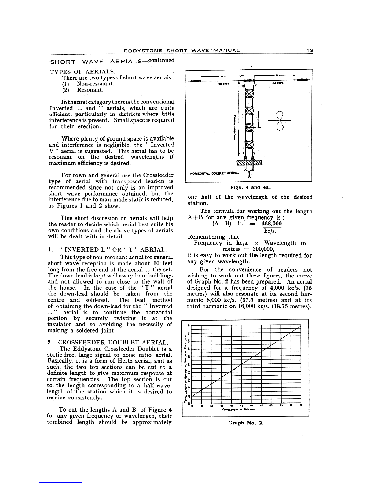
2. CROSSFEEDER DOUBLET AERIAL.
The Eddystone Crossfeeder Doublet is a
static -free, large signal to noise ratio aerial.
Basically, it is a form of Hertz aerial, and as
such, the two top sections can be cut to a
definite length to give maximum response at
certain frequencies. The top section is cut
to the length corresponding to a half -wave-
length of the station which it is desired to
receive consistently.
To cut' the lengths A and B of Figure 4
for any given frequency or wavelength, their
combined length should be approximately
Figs. 4 and 4a.
one half of the wavelength of the desired
station.The formula for working out the length
A -1-B for any given frequency is :
(A -}-B) ft. = 468,000
kc/s.
Remembering that
Frequency in kc/s. x Wavelength in
metres = 300,000,
it is easy to work out the length required for
any given wavelength.
For the convenience of readers not
wishing to work out these figures, the curve
of Graph No. 2 has been prepared. An aerial
designed for a frequency of 4,000 kc/s. (75
metres) will also resonate at its second har-
monic 8,000 kc/s. (37.5 metres) and at its
third harmonic on 16,000 kc/s. (18.75 metres).
Graph No. 2.
14 EDDYSTONE SHORT WAVE MANUAL
SHORT WAVE AERIALS-continued
The length of. feeder_ lint_from the receiver
to the aerial should be not, less than .a quarter
of a wavelength, i.e., greater. than (A+ B).
The inset, Fig. 4(a), shows the directional
property of the doublet, the aerial receiving
the most energy from a direction at right
angles to its own plane.
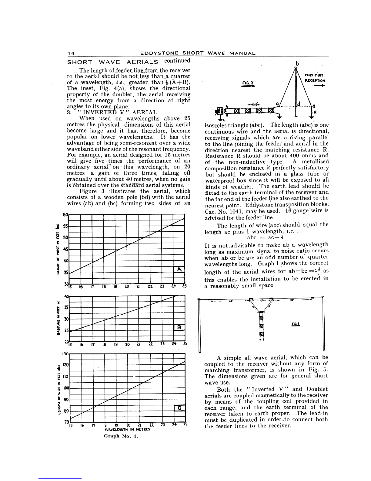
3. " INVERTED V " AERIAL.
When used on wavelengths above 25
metres the physical dimensions of this aerial
become large and it has, therefore, become
popular on lower wavelengths. It has the
advantage of being semi -resonant over a wide
waveband either side of the resonant frequency.
For example, an aerial designed for 15 metres
will give five times the performance of an
ordinary aerial- on this wavelength, on 20
metres a gain of three times, falling off
gradually until about 40 metres, when no gain
is -Obtained over the stand-S.tcratrial systems.
Figure 3illustrates the aerial, which
consists of a wooden pole (bd) with the aerial
wires (ab) and (bc) forming two sides of an
ov
55
50
45
40
35.
CIS 16 17 18 19 20 2.1 22. 23 24 21
.-----j- -
;
....0,----------------------
1.---------- IB
)15 16 17 18 19 20 21 22. 23 24 2'
130
120
gno
100
t 90
ao
70
C
15 16 17 IS 19 20 21 22 23 421
WAVELENGTH IN METRES
Graph No. 1.
FIG. 3
.A1114
ciiiNM
A
111111F:4i
isosceles triangle (abc). The length (abc) is one
continuous wire and the aerial is directional,
receiving signals which are arriving parallel
to the line joining the feeder and aerial in the
direction nearest the matching resistance R.
Resistance R should be about 400 ohms and
of the non -inductive type. A metallised
composition resistance is perfectly satisfactory
but should be enclosed in a glass tube or
waterproof box since it will be exposed to all
kinds of weather. The earth lead should he
fitted to the earth terminal of the receiver and
the far end of the feeder line also earthed to the
nearest point. Eddystone transposition blocks,
Cat. No. 1041, may be used. 16 gauge wire is
advised for the feeder line.
The length of wire (abc) should equal the
length ac plus 1 wavelength, i.e.:
abc = ac+ A
It is not advisable to make ab a wavelength
long as maximum signal to noise ratio occurs
when ab or bc are an odd number of quarter
wavelengths long. Graph 1 shows the correct
length of the aerial wires for ab=bc =::A as
this enables the installation to be erected in
a reasonably small space.
MAXIMUM
REcernoN
A simple all wave aerial, which can be
coupled to the receiver without any form of
matching transformer, is shown in Fig. 5.
The dimensions given are for general short
wave use.
Both the " Inverted V " and Doublet
aerials are coupled magnetically to the receiver
by means of the coupling coil provided in
each range, and the earth terminal of the
receiver taken to earth proper. The lead-in
must be duplicated in order .to connect both
the feeder lines to the receiver.

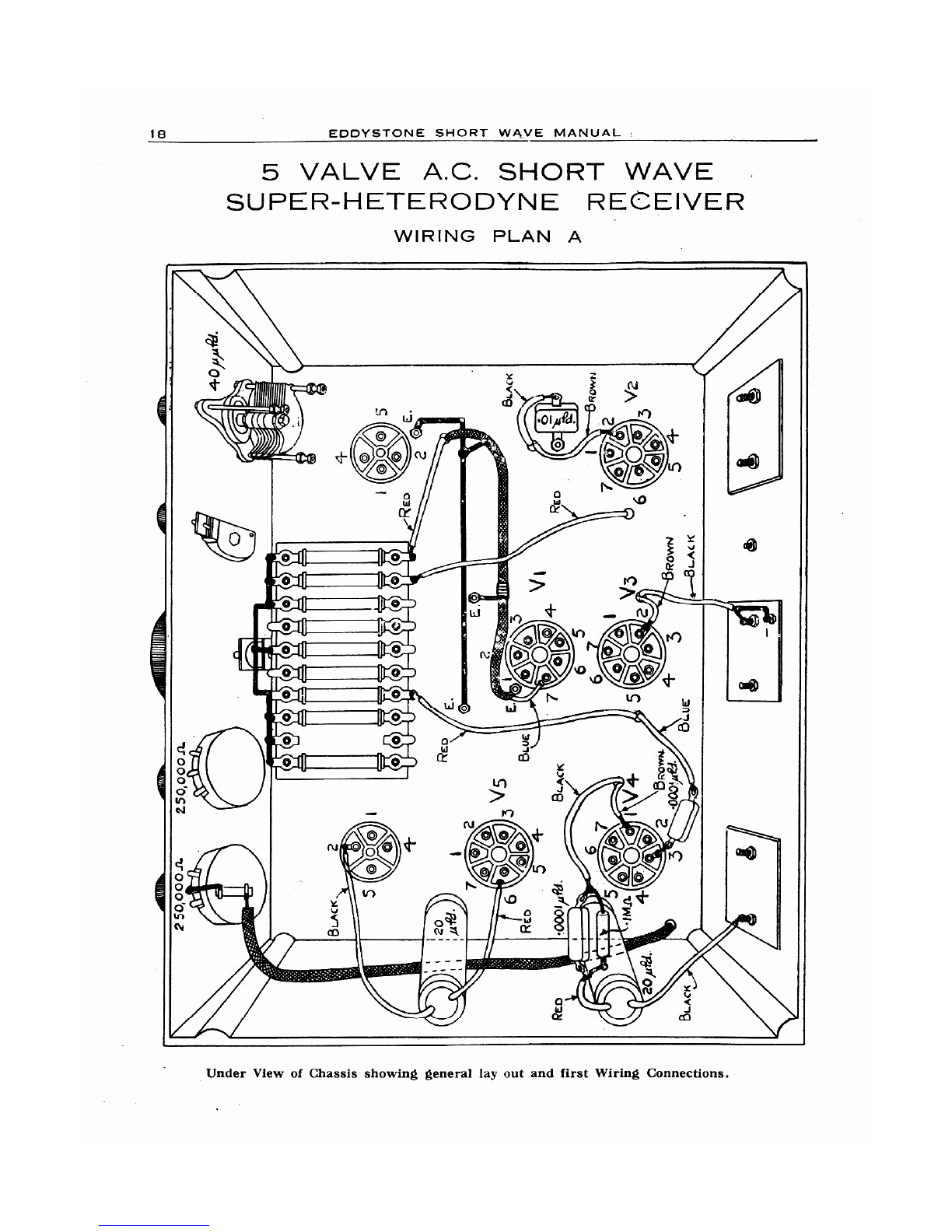
EDDYSTONE SHORT WAVE MANUAL 15
5 VALVE
SHORT WAVE SUPER-HETERODYNE
RECEIVER
FOR A.C. MAINS 1 3.6 TO 80 METRES
This set, which has a first-class all round
performance, is the result of our wish to
produce at moderate cost a powerful and
efficient A.C. super -heterodyne receiver, com-
bining the advantages of automatic volume
control, and a degree of selectivity adequately
capable of meeting present-day demands.
As with the battery model, the avoidance
of complicated design presents some difficulty,
but here we have a simple yet powerful set,
which is not difficult to build, and is easy to
trim and gang without the necessity of elabor-
ate equipment.
The short wave performance is probed,
and the set can be adapted by interchangeable
coils for medium and long waves without loss
in efficiency.
The newcomer to constructional radio is
not recommended to tackle this set as a
first effort. The " Everyman's Short Waver,"
battery model on pages 8 to 11, is preferable
as it is an extremely simple set for the beginner
and no special technical knowledge is necessary.
The circuit of the A.C. super -heterodyne
receiver embodies an X41 triode heptode
valve as frequency changer, followed by two
I.F. stages tuned to 465 K/cs. Then comes a
double diode triode valve, one diode for
detection, the other for automatic volume
control.
The triode portion is used as a low
frequency amplifier, resistance capacity
coupled into a steep slope pentode output
valve. The coils are easily interchangeable
so that the receiver can be used on any wave-
length between 13.6 and 2,000 metres.
To avoid complications, no H.F. stage is
built into the receiver circuit. The H.F.
pre -selector unit, described on page 34, can be
added to the receiver at a later date if desired.
The performance is very good on all wave-
lengths, the set covering both medium and
long wave -bands without any loss of efficiency
on the short waves.
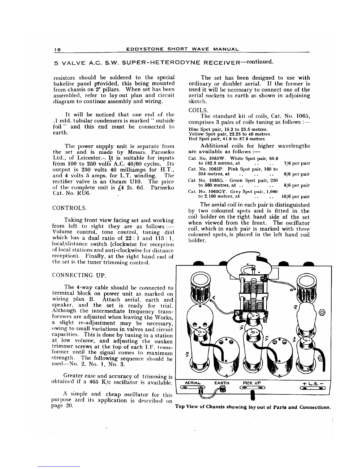
CONSTRUCTION.
The views of top and underside of chassis
show the lay out of the parts, and the point to
point wiring is easy to follow.
The metal chassis affords rigid and robust
assembly which means complete stability of
operation. The drawings give a clear general
outline of assembly but the following points
are of guidance. First mount valveholders,
scraping paint from chassis at all points of
earthing. The terminal panels are fixed with
6BA screws, earth connections being obtained
from one screw on each of these panels. The
16 EDDYSTONE SHORT WAVE MANUAL
5 VALVE A.C. S.W. SUPER -HETERODYNE RECEIVER-continued.
resistors should be soldered to the special
bakelite panel ptovided, this being mounted
from chassis on 2" pillars. When set has been
assembled, refer to lay out plan and circuit
diagram to continue assembly and wiring.
It will be noticed that one end of the
.1 mfd. tubular condensers is marked " outside
foil " and this end must he connected to
earth.
The power supply unit is separate from
the set and is made by Messrs. Parmeko
Ltd., of Leicester., 1 t is suitable for inputs
from 100 to 250 volts' A.C. 40/60 cycles. Its
output is 250 volts 40 milliamps for H.T.,
and 4 volts 5 amps. for L.T. winding. The
rectifier valve is an Osram U10. The price
of the complete unit is £4 2s. 6d. Parmeko
Cat. No. R116.
CONTROLS.
Taking front view facing set and working
from left to right they are as follows :-
Volume control, tone control, tuning dial
which has a dual ratio of 22 : 1 and 115: 1,
local/distance switch (clockwise for reception
of local stations and anti -clockwise for distance
reception). Finally, at the right hand end of
the set is the tuner trimming control.
CONNECTING UP.
The 4 -way cable should be connected to
terminal block on power unit as marked on
wiring plan B. Attach aerial, earth and
speaker, and the set is ready for trial.
Although the intermediate frequency trans-
formers are adjusted when leaving the Works,
aslight re -adjustment may be necessary,
owing to small variations in valves and circuit
capacities. This is done by tuning in a station
at low volume, and adjusting the sunken
trimmer screws at the top of each I.F. trans-
former until the signal comes to maximum
strength. The following sequence should be
used --No. 2, No. 1, No. 3.
Greater ease and accuracy of trimming is
obtained if a 465 K/c oscillator is available.
A simple and cheap oscillator for this
purpose and its application is described on
page 20.
The set has been designed to use with
ordinary or doublet aerial. If the former is
used it. will be necessary to connect one of the
aerial sockets to earth as shown in adjoining
sketch.
COILS.The standard kit of coils, Cat. No. 1065,
comprises 3 pairs of coils tuning as follows :-
Blue Spot pair, 15.3 to 25.5 metres.
Yellow Spot pair, 23.25 to 46 metres.
Red Spot pair, 41.8 to 87.8 metres.
Additional coils for higher wavelengths
arc available as follows :-
Cat. No. 1065W. White Spot pair, 85.8
to 182.5 metres, at
Cat. No. 1065P. Pink Spot pair, 160 to
354 metres, at
Cat No. 1065G. Green Spot pair, 250
to 560 metres, at ..
Cat. No. 1065GY. Grey Spot pair, 1,080
to 2,100 metres, at
7!6 per pair
8/6 per pair
8/6 per pair
10/6 per pair
The aerial coil in each pair is distinguished
by two coloured spots and is fitted in the
coil holder on the right hand side of the set
when viewed from the front. The oscillator
coil, which in each pair is marked with three
coloured spots, is placed in the left hand coil
holder.
AERIAL EARTH PICK VP +-
Top View of Chassis showing layout of Parts and Connections.

EDDYSTONE SHORT WAVE MANUAL 17
5 VALVE A.C. S.W. SUPER -HETERODYNE
RECEIVE R-continued
EDDYSTONE PARTS Price
1 Dual Ratio Dial, Cat. No. 1045 .. .. 12/6
12 -gang Condenser, 150 m.mfd. Sections,
Cat. No. 967 .. .. .. 17/6
IKit I.F. Transformers, complete with
Screened Anode Leads and Valve
(Cat. No. 1056, 465 K/cs.) Cowls .. 30/0
2 4 -pin Valveholders, Chassis Type 9.53,
10d. each .. .. .. .. 1/8
5 7 -pin Valveholders, 985, 1/4 each .. 6/8
1Microdenser, Type 900/40 .. .. 4/3
1 Aluminium Die-cast Chassis, drilled all
necessary holes, finished inside and
out battleship grey cellulose .. 18/6
2 r 6BA Erinoid Pillars, type 8P, 2d. each 4d.
4 1" Black Knobs, *" hole, 6d. each .. 2/0
3 Terminal Panels (Chassis) with Plugs and
Sockets, Cat. No. 1060, 9d. each 2/3
1Kit of Special Coils in Metal Box, Cat.
No. 1065, comprising 3 pairs, Types
LB, Y, R .. .. .. .. 21/0
MISCELLANEOUS PARTS
1 Rotary On -off Switch
2 Erie 250,000 ohm Potentiometers
2 20 mfd. 20 volt Electrolytic Condensers,
Dubilier, type 402 ..
110 -way Resistance Strip, Bulgin
9 .1 mfd. Wire -end Condensers, B.I., Dubilier
or T.C.C.
7 Dubilier, type 670, .01 mfd. Condensers
5 Dubilier, type 670, .0001 mfd. Condensers
1Dubilier, type 670, .001 mfd. Condenser 6
2 Dubilier, type 670, .002 mfd. Condensers
2 100 ohm I watt Resistors, Erie or Dubilier
1145 ohm * watt Resistor, Erie or Dubilier
3 200 ohm 1 watt Resistors, Erie or Dubilier
11,000 ohm 1 watt Resistor, Erie or Dubilier
3 10,000 ohm 1 watt Resistors, Erie or Dubilier
115,000 ohm 1 watt Resistor, Erie or Dubilier
1 30,000 ohm 1 watt Resistor, Erie or Dubilier
1 40,000 ohm 1 watt Resistor, Erie or Dubilier
4 50,000 ohm 1 watt Resistors, Erie or Dubilier
1 60,000 ohm 1 watt Resistor, Erie or Dubilier
1 100,000 ohm 1 watt Resistor, Erie or Dubilier
1100,000 ohm watt Resistor, Erie or Dubilier
2 250,000 ohm watt Resistors, Erie or Dubilier
3 500,000 ohm * watt Resistors, Erie or Dubilier
110,000 ohm * watt Resistor, Erie or Dubilier
1 2 megohm, one watt Resistor, Erie or Dubilier
1 length 4 -way Cable, 11 yds.
1 W.O. Terminal
27 r x 6BA Nuts and Bolts .
20 6BA Tags ..
42 6BA Shake -proof Washers
7 ft. 16s.w.g. Tinned Copper Wire .. 00
7 ft. " Slide back " Connecting Wire
ACCESSORIES
VALVES.
1 Osram X.41 7 -pin Metallised
2 Mullard V.P.4 7 -pin Metallised
1 Mullard T.D.D.4 7 -pin Metallised
1 Mullard PEN, 4 V.B., 7 -pin
Approx. Total Cost with Valves . .
ox
oN0
Ioc
00000
t.
2.
14 2In
IN
0
,92.23J
40(51)
Ill
000'U. 024
Z13 7s. 6d.
POWER UNIT.
1 Supply Unit Type RU.6 (Parmeko) incorpor-
ating U.10 Osram Rectifier Valve L4 2s. 6d.
00IL
MIAS
010>
-.- 11' 02 a I41-
1
02 4
31tri ?11
o4
68
od-
41CLCIS/)
'en \ °Li
000-
41
0
vi
2
od (f)
Other manuals for Short Wave
1
Table of contents
Other Eddystone Telephone manuals


