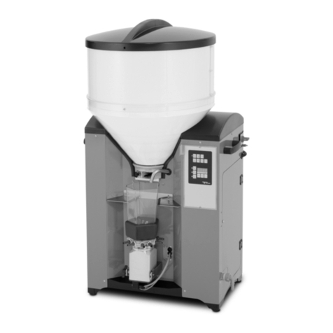
RNA STS 220-4 User manual

Operating Instructions
Step Feeders
STS 220-4
STS 220-6
STS 320-4
STS 320-6

Rhein-Nadel Automation GmbH 2
VT-MA-STS-EN_2019 / 11.03.2019 SJ
Table of Contents
1. Technical data........................................................................................................................ 4
1.1. Table................................................................................................................................... 4
1.2. Motor connection diagrams................................................................................................. 5
2. Safety directives..................................................................................................................... 5
2.1. Applicable directives and standards.................................................................................... 7
3. Design and functional description of step feeders.................................................................. 7
4. Shipment and installation ....................................................................................................... 8
4.1. Shipment............................................................................................................................. 8
4.2. Connecting the motor.......................................................................................................... 8
4.3. Installation........................................................................................................................... 8
5. Commissioning....................................................................................................................... 9
6. Maintenance........................................................................................................................... 9
6.1. Step frame motor ................................................................................................................ 9
6.2. Replacing the sliding skids of step plates ......................................................................... 10
6.3. Linear guides of step frames............................................................................................. 10
7. Spare parts and customer service........................................................................................ 10

Rhein-Nadel Automation GmbH 3
VT-MA-STS-EN_2019 / 11.03.2019 SJ
Declaration of Incorporation
according to Machinery Directive 2006/42/EC
We hereby declare that our product is intended to be incorporated into or assembled with other machinery to consti-
tute one machine in terms of the Directive indicated above (or parts thereof) and that it must not be put into operation
until the relevant machinery into which it is to be incorporated has been declared to be in conformity with the EC Ma-
chinery Directive.
Applied harmonised standards:
DIN EN 60204 T1, DIN EN ISO 12100-2011-03, DIN EN 619
Remarks:
This product has been manufactured in accordance with the Low-Voltage Directive 2014/35/EU.
We assume that our product will be incorporated into a stationary machine.
Rhein-Nadel Automation GmbH
Managing Director
Jack Grevenstein

Rhein-Nadel Automation GmbH 4
VT-MA-STS-EN_2019 / 11.03.2019 SJ
1. Technical data
1.1. Table
Type
STS 220-4
STS 220-6
STS 320-4
STS 320-6
E = filling height +/-50 (mm)
870
905
870
905
A = discharge height +/-50 (mm)
955
1250
945
1240
GH = total height +/-50 (mm)
1230
1480
1230
1480
GB = total width - large hopper
600
600
700
700
GB = total width - small hopper
550
550
650
650
GT = total depth
860
1000
900
1035
B = width of baseplate
500
500
600
600
T = depth of baseplate
630
700
670
740
SB = width of steps
218
218
318
318
ST = depth of steps
15/20/25/30
15/20/25/30
20/25/30/35
20/25/30/35
Number of steps
4
6
4
6
Footprint (GB x GT)
600 x 860
600 x 1000
700 x 900
700 x 1035
Strokes per minute
without VFD
29 (50Hz)
35 (60 Hz)
29 (50Hz)
35 (60 Hz)
29 (50Hz)
35 (60 Hz)
29 (50Hz)
35 (60 Hz)
Strokes per minute
with VFD
10 to 45
10 to 45
10 to 45
10 to 45
Hopper volume (L)
20/30
20/30
30/40
30/40
Max. filling weight (kg)
60
60
60
60
Large
hopper
Small
hopper

Rhein-Nadel Automation GmbH 5
VT-MA-STS-EN_2019 / 11.03.2019 SJ
1.2. Motor connection diagrams
Connection of three-phase motors
Sense of rotation is indicated by an arrow on the motor.
This area becomes visible after removal of the side cover.
For reversing the sense of rotation change two phases of the supply line
2. Safety directives
We have taken great care in design and manufacture of our step feeders in order to ensure smooth and safe opera-
tion. You, too, can make an important contribution towards safety at work. We therefore ask you to read these brief
operating instructions completely prior to commissioning the system. Observe the safety directives at all times!
Attention
This warning sign indicates safety directives. Non-observance of such warnings may cause serious injury
or even death!
Caution
This warning sign indicates safety directives. Non-observance of this warning may cause minor injury or
material damage.
Notice
This hand indicates useful tips for operation of the conveyors.
Make sure that all persons working with or at the equipment also read the following safety directives carefully and fol-
low them!
These Operating Instructions only apply to the equipment types indicated on the cover page.
They must be available at all times at the place of installation of the step feeders.
If the step feeders are to be used in a humid or wet environment (wet area) make sure that the required degree of pro-
tection is provided.
Connection to three-phase
supply
Low voltage
3x230V
Connection to three-phase
supply
High voltage
3x400V

Rhein-Nadel Automation GmbH 6
VT-MA-STS-EN_2019 / 11.03.2019 SJ
Notice
For comprehensive information on the full range of control devices please refer to the 'Control Units' oper-
ating instructions.
Any commissioning, retooling, maintenance and repair work shall be carried out by qualified and authorized personnel
only (see also 'Operator's duties' in this section).
For installation, maintenance and repair work all poles of the power supply must be disconnected from the conveyor in
compliance with VDE provisions.
Any work on the electrical equipment shall be carried out exclusively by a professional electrician, or by instructed per-
sons working under the supervision of a professional electrician, according to electrotechnical rules.
Attention
Risk of injury and electric shock hazard!
•The equipment user and operators shall ensure that only authorized personnel works at the step feeder.
•Any changes that have occurred on the feeding system affecting safety shall immediately be reported to the us-
er.
•Operate the step feeder in perfect condition only!
•Use the step feeder only for its intended use.
•Observe the accident prevention provisions VBG 10 for continuous conveyors and VBG 4 for electrical equip-
ment and components"
Machine hazards
•If the step feeder comes into contact with moisture or liquids there is risk of electric shock.
•Make sure that protective earthing of the power supply system is in perfect condition.
•Never operate the step feeder without guards and cover panels in place!
Intended use
The intended use of the step feeders is the storage and feeding of parts.
The shortest side of such parts must be at least 1 mm long.
Select the step feeder model (size) and step depth according to the size of the parts handled to make sure that the
parts can be conveyed by means of the step plates.
Caution
Small parts and parts with small outer contours may get lodged in the gaps of the step frames and causing
damage or equipment failure.
Caution
Dirt deposits on the parts to be handled may get lodged in the gaps of the step frames and cause damage,
equipment failure or excessive sliding skid wear.
Caution
Dirt from the parts handled may enter the linear guide units of the step frames and cause damage, equip-
ment failure or excessive runner block wear.
For permitted hopper loading see Technical Data in Section 1.
Product must not be dumped into the hopper from great height. The maximum permitted impact energy is 0.2 J.
Noise emission
The constant sound pressure level is 70 dB(A) max. Specific part handling applications may result in higher noise lev-
els. For such exceptional cases noise abatement options are available from manufacturer.

Rhein-Nadel Automation GmbH 7
VT-MA-STS-EN_2019 / 11.03.2019 SJ
Equipment user's duties
Commissioning, retooling, maintenance and repair work shall be performed by qualified and authorized personnel on-
ly.
We distinguish between four qualification levels:
Qualified personnel
refers to persons who are familiar with installation, start-up and operation of the step feeder. Their qualifications are
appropriate for their activities.
Authorized personnel
refers to qualified personnel that has been assigned a clearly defined task by the user of the step feeder.
Qualified electrical worker
According to IEC 364 and DIN VDE 0105 Part 1, the term 'qualified electrical worker' refers to persons who, through
their professional training, know-how and experience and through their knowledge of applicable standards are able to
assess the work assigned to them and to recognize potential hazards.
Instructed person
According to IEC 364 and DIN VDE 0105 Part 1, the term 'instructed person' refers to persons who have been in-
structed in the tasks assigned to them by a qualified electrical worker. These persons have also been briefed on po-
tential dangers resulting from inappropriate behaviour, and on the requisite guards and precautions to be used/taken.
2.1. Applicable directives and standards
The step feeder has been manufactured in accordance with the following directives:
•EC Machinery Directive 2006/42/EC
•EC Low-Voltage Directive 2014/35/EU
•Electromagnetic Compatibility Directive 2014/30/EU
We assume that our product will be incorporated into a stationary machine. The requirements of the EMC Directive
must be satisfied by the user.
The applicable standards are specified in the Declaration of Incorporation.
3. Design and functional description of step feeders
Fill the parts to be conveyed (bulk products) into hopper (5). Please observe the filling quantity indicated on the hop-
per. In the hopper the parts are transferred to the step plate of the step frame. The step frames (2) and (3) oscillate up
and down in reciprocating manner between the side panels of the base frame (1). The parts are moved up by the first
plate. Due to the incline of the feeder and the projection of the steps involved, parts are transferred from one step plate
to the next plate when one step frame reaches the top of its motion (reversal point), at which point the other frame is at
the bottom of its motion. The parts are now moved up by this step plate and transferred to the next step plate etc. until
the parts exit the step frame at the topmost point. The parts exiting the step feeder slide down a chute to the down-
stream equipment.
Control of the step feeder is effected, depending on motor type, by motor protection breaker or electronic control de-
vices.
Notice
For information on the control devices please refer to the separate 'Control Units' operating instructions.

Rhein-Nadel Automation GmbH 8
VT-MA-STS-EN_2019 / 11.03.2019 SJ
4. Shipment and installation
4.1. Shipment
Delivery ex works
Step feeders are delivered ex works in wooden crates.
On-site moving
For handling the step feeder you need a fork lift truck or suitable lifting equipment to move the step feeder to its place
of installation.
Note that the step feeders are always bolted to the base plate of the crate or pallet.
When lifting the step feeder always attach the lifting gear to the base frame, never to the cabinet or any mounted com-
ponents. For handling we recommend using a forklift and placing the forks underneath the base plate. Position the
forks in relation to the levelling feet such as to prevent tilting of the step feeder.
Attention
Check all guards when unpacking. Replace any damaged parts before commissioning!
4.2. Connecting the motor
Have a professional electrician connect the motor in accordance with the circuit diagram (see chapter 1). After that,
check the sense of rotation.
Attention
Provide suitable overload protection for the motor. The characteristics of the motor can be found on its rat-
ing plate.
Caution
Motor protection breakers supplied unfitted must not be installed upside down as this would disable their
protective function. Be sure to install the circuit-breakers in the specified orientation.
4.3. Installation
Attention
It is absolutely mandatory to anchor the supporting substructure to the foundation. Operation of unan-
chored equipment is not permitted!

Rhein-Nadel Automation GmbH 9
VT-MA-STS-EN_2019 / 11.03.2019 SJ
5. Commissioning
Attention
Electrical connection of the step feeder must be made by trained professional electricians only!
When making any change to the electrical connection be sure to observe the operating instructions for the
motor circuit-breaker / control unit.
The step feeder is started and stopped at the motor circuit-breaker.
Fig. 10: Motor protection breaker
For step feeders with other control units please refer to the separate user's manual of the control unit.
First let the step feeder run for about 5 min. without product. During this time verify that the step feeder runs smoothly
and without any trouble. No metal components of the step frames must touch each other.
6. Maintenance
Attention
For installation, maintenance and repair work all poles of the power supply must be disconnected from the
step feeder in compliance with VDE provisions. Any work on electrical equipment of the step feeder shall
be carried out exclusively by a professional electrician, or by instructed persons (see chapter 2) working
under the direction and supervision of a professional electrician, according to electrotechnical rules.
Clean the step feeder at regular intervals to ensure smooth mechanical action. The cleaning intervals are to be set by
the user depending on the condition of the parts to be handled and on the specific ambient conditions prevailing at site
but should not be longer than once a week. During cleaning, check the sliding skids on the step plates for wear and
apply a thin layer of oil. The sliding skids prevent the metal components from touching each other. Replace the sliding
skids when the gap sizes are reduced to approx. 0.1 to 0.2 mm.
Check the following once a day:
1. Absence of foreign matter or rejects in the equipment
2. Tight fit of machine parts and proper transition areas
3. Tightness of spring steel plates of steps
If any one of these points is not fulfilled stop the equipment and initiate repairs and/or adjustments.
6.1. Step frame motor
Motor and gearbox are low-maintenance units. In normal operation no re-lubrication or lubricant change is required.
0
1
On
Off

Rhein-Nadel Automation GmbH 10
VT-MA-STS-EN_2019 / 11.03.2019 SJ
6.2. Replacing the sliding skids of step plates
To remove the sliding skids of the step plates dismount the step bar and lift out the skids. Step plates fitted with gap
blockers have additional lateral sliding skids in said blockers. To replace these sliding skids it is necessary to dismount
all step plates first. To do so, remove the front cover underneath the hopper of the step feeder. Now you can dismount
the step plates from bottom to top. For installation proceed from top to bottom. Take care to remount the screw locking
devices, if any.
Step bar Sliding skid Lateral sliding skids in gap blockers Gap blocker
6.3. Linear guides of step frames
The linear guides of the step frames come with an initial charge of grease. The greases used are standard types such
as for antifriction bearings, with a base oil viscosity of 200 mm2/s at 40 °C. See table below for examples. Lubricants
containing MoS2 or graphite are prohibited.
Recommended greases for standard applications
HIWIN
G05
Klüber
MICROLUBE GL-261
Mobil
Mobilux EP1
Fuchs Lubritech
Lagermeister BF2
Lubcon
TURMOGREASE CAK 2502
Recommended lubricant charge for HIWIN HG_25 series
Initial lubrication
Relubrication
0.8 grammes (3x)
1.2 grammes
For initial lubrication, add the quantity of grease specified in the table by slow operation of the grease gun. Move the
runner block three times by a distance equalling approx. three times its length. Repeat the procedure described twice
more. Next move the runner block through its complete travelling distance and check that a film of lubricant is visible
on the complete rail. If not, add more lubricant.
If re-lubrication is required, dismount the covers on the side panels. In order to access the lubricating nipples (2 per
runner block) move the step frames until the runner blocks are in the area of the openings.
7. Spare parts and customer service
For an overview of genuine spare parts available please refer to the separate spare parts list.
In order to make sure that your order is processed swiftly and correctly please specify the device type (see rating
plate), the quantity required, the spare part designation and the spare part number.
For a list of Service Center addresses refer to the back cover page of this manual.

RNA Group
Headquarters
Manufacturing and Sales
Rhein-Nadel Automation GmbH
Reichsweg 19-23
D-52068 Aachen
Phone: +49 (0) 241-5109-0
Fax: +49 (0) 241-5109-219
www.RNA.de
Further RNA group companies:
Manufacturing and Sales
Focus: Pharmaceutical Industry
PSA Zuführtechnik GmbH
Dr.-Jakob-Berlinger-Weg 1
D-74523 Schwäbisch Hall
Phone: +49 (0) 791 9460098-0
Fax: +49 (0) 791 9460098-29
www.psa-zt.de
Manufacturing and Sales
Unit C
Castle Bromwich Business Park
Tameside Drive
Birmingham B35 7AG
United Kingdom
Phone: +44 (0) 121 749-2566
Fax: +44 (0) 121 749-6217
E-mail: RNA@RNA-uk.com
www.rnaautomation.com
Manufacturing and Sales
HSH Handling Systems AG
Wangenstr. 96
CH-3360 Herzogenbuchsee
Switzerland
Phone: +41 (0) 62 956 10-00
Fax: +41 (0) 62 956 10-10
E-mail: info@handling-systems.ch
www.handling-systems.ch
Manufacturing and Sales
Pol. Ind. Famades c/Energia 23
E-08940 Cornella de Llobregat (Barcelona)
Spain
Phone: +34 (0)93 377-7300
Fax: +34 93 377-6752
E-Mail: info@vibrant-RNA.com
www.vibrant-RNA.com
www.vibrant.es
Further manufacturing sites
of the RNA Group
Manufacturing
Lüdenscheid branch
Rhein-Nadel Automation GmbH
Nottebohmstraße 57
D-58511 Lüdenscheid
Phone: +49 (0) 2351 41744
Fax: +49 (0) 2351 45582
E-Mail: werk.luedenscheid@RNA.de
Manufacturing
Ergolding branch
Rhein-Nadel Automation GmbH
Ahornstraße 122
D-84030 Ergolding
Phone: +49 (0) 871 72812
Fax: +49 (0) 871 77131
E-Mail: werk.ergolding@RNA.de
This manual suits for next models
3
Table of contents
Other RNA Wire Feeder manuals