Edge EDGE-1830 User manual

Original Instruction Manual CD-941-450-1
EDGE-1830, EDGE-2440, EDGE-3240, EDGE-2460
EDGE-3260, EDGE-3860, EDGE-4460, EDGE-3270
ORIGINAL INSTALLATION &
OPERATING MANUAL (G2)
FOR EXPORT DESTINATIONS: AT, BE, CH, CY, CZ,
DE, DK, EE, ES, FI, FR, GB, GR, HU, IE, IT, LT,
LU, LV, NL, NO, PL, PT, RO, SE, SI, SK, TR
RETAIN THIS MANUAL FOR FUTURE REFERENCE
TO BE SERVICED BY AUTHORIZED PERSONS ONLY
MF&B RESTAURANT SYSTEMS, INC.
133 ICMI ROAD, DUNBAR, PA 15431, USA
1-888-480-EDGE
T: +00 (1) 724.628.3050
F: +00 (1) 724.626.0247
WWW.EDGEOVENS.COM
Revision 1.0, July 2019

EDGE-1830 / EDGE-2440 / EDGE-3240 / EDGE-2460 / EDGE-3260 / EDGE-3860 / EDGE-4460 / EDGE-3270
Installation and Operating Manual
Original Instruction Manual ii Rev 1.0, July 2019
SAFETY INFORMATION
The purchaser of this gas appliance has the responsibility to post in a prominent
location instruction to be followed in the event the user smells gas. This
information shall be obtained by consulting the local gas supplier. This appliance
has been testedand approved for the application of use in the food service industry
only. Other uses, outside of the approved application are neither supported nor
condoned by the manufacture.
FOR YOUR SAFETY
•This appliance is for professional use and shall be used by qualified people.
•Minimum clearance from combustible or non-combustible construction is 6
inches from side and 6 inches from back.
•It may be required to allow clearance for service accessibility.
•Do not operate without oven base provided by manufacturer.
•Suitable for use on combustible floors.
•This appliance shall be installed in conformity with the current regulations and
used only in a well-ventilated location.
•This appliance shall be installed by qualified people.
•Fuel conversions shall be performed by qualified people.
•Consult the instructions before installing and using this appliance.
•Do not store or use gasoline or other flammable vapors or liquids in the vicinity
of this or any other appliance.
WARNING
•Improper installation, adjustment, alteration, servicing or maintenance can
result in property damage, injury, or death. Read this entire manual and ensure
that you thoroughly understand all instructions before installing, operating, or
servicing this equipment.
•Keep the appliance free and clear of combustibles.
•Do not obstruct the flow of combustion or ventilation air to and from the oven.
There should never be any obstructions on or around the oven that could
hamper the flow of combustion or ventilation air to or from the oven. Any
changes to the area where the oven is to be installed must not affect the
combustion or ventilation air to and from the oven.
•This appliance is to be installed with enough ventilation to prevent the
occurrence of unacceptable concentrations of substances harmful to health in
the room which it is installed

EDGE-1830 / EDGE-2440 / EDGE-3240 / EDGE-2460 / EDGE-3260 / EDGE-3860 / EDGE-4460 / EDGE-3270
Installation and Operating Manual
Original Instruction Manual iii Rev 1.0, July 2019
IMPORTANT
•Retain all shipping materials until you are certain that the oven has not been
damaged (either externally or internally) during shipment. Thoroughly inspect
the oven on receipt for both external and internal damage. It is solely the
customer's responsibility to report any shipping damage to the freight
company.
NOTICE
•Oven installation, including electrical and natural gas connections, oven
placement, and ventilation must comply with all applicable national and local
codes. National and local codes supersede the recommendations,
requirements, and guidelines contained in the manual.
•The purchaser of this equipment is required to prominently post instructions to
be followed should the user smell natural gas. This information shall be
obtained from the local natural gas supplier.
•Installing any part(s) not provided by the Edge oven OEM shall void the warranty
and release the OEM from any and all liabilities.
•Those parts which have been protected by the manufacture or authorized
agents shall not be adjusted by the user.
•The oven electrical wiring diagram is located inside the control compartment.

EDGE-1830 / EDGE-2440 / EDGE-3240 / EDGE-2460 / EDGE-3260 / EDGE-3860 / EDGE-4460 / EDGE-3270
Installation and Operating Manual
Original Instruction Manual 1 Rev 1.0, July 2019
Table of Contents
Section Page
OVEN COMPONENTS AND OPERATION____________________________________________ 3
COMPONENTS ____________________________________________________________________ 3
INSTALLATION INSTRUCTIONS___________________________________________________ 5
TOOLS & EQUIPMENT REQUIRED _____________________________________________________ 6
STACKING THE OVENS ______________________________________________________________ 7
WINDOWS _______________________________________________________________________ 9
END PLUGS REMOVAL & INSPECTION __________________________________________________ 9
CONVEYOR INSTALLATION__________________________________________________________ 10
NOTE REGARDING SPLIT-BELT CHAIN INSTALLATION_____________________________________________ 12
STANDARD ACCESSORIES___________________________________________________________ 13
Heat Shields _____________________________________________________________________________ 13
Chain Guards ____________________________________________________________________________ 13
Crumb Pans______________________________________________________________________________ 14
Belt Stops _______________________________________________________________________________ 14
Columnating Panels _______________________________________________________________________ 14
FINGER ASSEMBLIES_______________________________________________________________ 14
FINAL CONNECTIONS ______________________________________________________________ 17
RESTRAINT CABLE_________________________________________________________________ 17
DECOMMISSIONING AND DISPOSAL _____________________________________________ 18
EDGE-1830-CUTSHEET ________________________________________________________ 19
EDGE-2440-CUTSHEET ________________________________________________________ 20
EDGE-3240-CUTSHEET ________________________________________________________ 21
EDGE-2460-CUTSHEET ________________________________________________________ 22
EDGE-3260-CUTSHEET ________________________________________________________ 23
EDGE-3860-CUTSHEET ________________________________________________________ 24
EDGE-4460-CUTSHEET ________________________________________________________ 25
EDGE-3270-CUTSHEET ________________________________________________________ 26
SPECIFICATIONS _____________________________________________________________ 27
OVEN START-UP __________________________________________________________________ 28
OVEN SHUTDOWN ________________________________________________________________ 28
OVEN OPERATION ___________________________________________________________ 29
Menu System Overview____________________________________________________________ 29

EDGE-1830 / EDGE-2440 / EDGE-3240 / EDGE-2460 / EDGE-3260 / EDGE-3860 / EDGE-4460 / EDGE-3270
Installation and Operating Manual
Original Instruction Manual 2 Rev 1.0, July 2019
Basic Operation __________________________________________________________________ 29
Advanced Operation ______________________________________________________________ 30
OVEN VENTILATION __________________________________________________________ 34
Ventilation Recommendations ______________________________________________________ 34
EDGE Control System, Error Codes_______________________________________________ 35
PREVENTATIVE MAINTENANCE _________________________________________________ 39
MAINTENANCE PART LIST __________________________________________________________ 42
EDGE OVEN WARRANTY POLICY & PROCEDURE____________________________________ 44
COMPANY INFORMATION _____________________________________________________ 45
CE DECLARATION ____________________________________________________________ 46

EDGE-1830 / EDGE-2440 / EDGE-3240 / EDGE-2460 / EDGE-3260 / EDGE-3860 / EDGE-4460 / EDGE-3270
Installation and Operating Manual
Original Instruction Manual 3 Rev 1.0, July 2019
OVEN COMPONENTS AND OPERATION
COMPONENTS
1. Control Can Assembly: Houses the operating controls for the oven and the natural
gas control devices and burner.
2. End Plug, Upper: Closes off the top half of the bake chamber, above the conveyor
belt.
3. End Plug, Lower: Closes off the bottom half of the bake chamber, below the
conveyor belt.
4. Conveyor Belt: Runs horizontally through the bake chamber; caries the product
through the oven.
5. Oven Base: Supports and insulates the bottom of the oven.
6. Oven Lid: Mounts to the top of the oven, finishes off the oven stack and covers the
oven insulation.
7. Half-Bake Window: Opens to allow the product to be placed halfway through oven
(half bake time).
8. Crumb Pan: Located under both the entrance and exit of the conveyor belt, catches
debris that falls through the conveyor belt.
9. Back Assembly: Closes off the back of the bake chamber.
10.Plenum Assembly: Houses the hot air blower motor and fan, and thermocouples to
monitor hot air temperature.
11.Oven Bottom: Mounts to the top of the oven base, seals off the stack and covers the
oven insulation.
12.Oven Legs: Used with single- and double-stack configurations to raise lower oven to
convenient working heights.
13.Oven Casters: Used on all oven configurations to allow moving the oven for
installation and servicing.
14.Restraining Device: Secures the oven base to the wall to avoid damage to gas and
electrical connections.

EDGE-1830 / EDGE-2440 / EDGE-3240 / EDGE-2460 / EDGE-3260 / EDGE-3860 / EDGE-4460 / EDGE-3270
Installation and Operating Manual
Original Instruction Manual 4 Rev 1.0, July 2019

EDGE-1830 / EDGE-2440 / EDGE-3240 / EDGE-2460 / EDGE-3260 / EDGE-3860 / EDGE-4460 / EDGE-3270
Installation and Operating Manual
Original Instruction Manual 5 Rev 1.0, July 2019
INSTALLATION INSTRUCTIONS
IMPORTANT REQUIREMENTS
Oven installation must comply with local codes or, if local codes do not exist, with the National
Fuel Gas Code, ANSI Z223.1/NFPA 54 OR Natural Gas Installation Code, CAN/CGA-B149.1, or
the Propane Gas Installation Code, CAN/CSA-B149-2, as applicable.
This appliance must be electrically grounded in accordance with local codes, or if local codes
do not exist, with the National Electrical Code, ANSI/NFPA 70. OR with the Canadian Electrical
Code, CSA C22.2.
When this appliance is installed with casters, it must be installed with the casters supplied, a
connector complying with ANSI Z21.69 / CAN/CGA-6.16, a quick-disconnect device complying
with ANSI Z21.41, and a mechanism to limit movement of the appliance without straining the
connector or its associated piping system. This quick-disconnect device must not exceed 1.5
meters in length.
The gas supply tubing or hose shall comply with the national requirements in force and shall
be periodically examined and replaced as necessary.
This appliance and its individual manual shutoff valves must be disconnected from the gas
supply piping system during any pressure testing of gas supply piping at pressures exceeding
1/2 psi (3.5 kPa).
The installer of this oven must contact local building and fire officials concerning inspections
and installation requirements of this oven and its ventilation system.
Unless otherwise stated, parts protected by the manufacturer or the authorized agent shall not
be adjusted by the installer.
In the event this appliance is to be converted to a gas type other than which it was originally
adjusted for, contact manufacture or authorized agent for the appropriate conversion kit.
(correct orifice, correct appliance decal, and instructions)

EDGE-1830 / EDGE-2440 / EDGE-3240 / EDGE-2460 / EDGE-3260 / EDGE-3860 / EDGE-4460 / EDGE-3270
Installation and Operating Manual
Original Instruction Manual 6 Rev 1.0, July 2019
TOOLS & EQUIPMENT REQUIRED
LIFTING SYSTEM
(2) EDGE Lifting Jacks, PN: IE-9001, Genie Lift or similar lifting system
(2) EDGE Lifting Plates, PN: IE-9100-xx (Inquire when placing order)
(1) EDGE installation cart, PN: IE-9201, 4-wheel cart, pallet jack, or similar.

EDGE-1830 / EDGE-2440 / EDGE-3240 / EDGE-2460 / EDGE-3260 / EDGE-3860 / EDGE-4460 / EDGE-3270
Installation and Operating Manual
Original Instruction Manual 7 Rev 1.0, July 2019
(1) 10ft, SCH40 steel pipe, 3” O.D. or 2.5” I.D. (Sourced locally)
(2) Clamps or locking pliers, when not using EDGE Lifting Jacks IE-9001.
HAND TOOLS
(1) #2 Phillips Screwdriver
(1) Ratchet and short extension
(1) 5/16” Socket or nut driver
(1) 7/16” wrench
(1) 9/16” Socket
(1) 3/8” Socket or wrench *oven back
(1) Tin snips for cutting banding
(1) Adjustable wrench (Crescent) *as needed
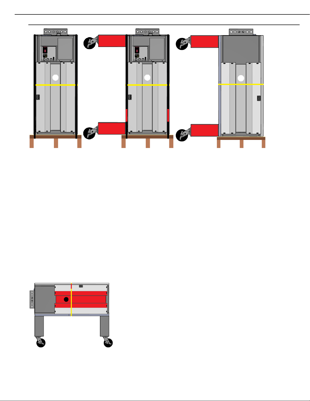
STACKING THE OVENS
1. Unpackage BOTTOM oven, retaining all attached documents and DO NOT cut any banding at this
point, the oven must remain attached to the cart or pallet. Inspect the oven for concealed shipping
damage before continuing.
2. Use dolly or cart to move the oven to the installation location, allow enough room for the oven to
be lifted, rotated, and stacked.
3. Cut ONLY the banding straps which secure the oven to the pallet or cart.
4. Set conveyor belt and other accessories to the side for later installation.
5. Attach Legs and casters (legs are not used in a triple stack) using 9/16” socket.
EDGE-1830 / EDGE-2440 / EDGE-3240 / EDGE-2460 / EDGE-3260 / EDGE-3860 / EDGE-4460 / EDGE-3270
Installation and Operating Manual
Original Instruction Manual 8 Rev 1.0, July 2019
6. If lifting plates are not installed, install them at this time. They are to be fitted between the end
plugs, secured with 4 of the existing black wing nuts. The offset 3” hole is to be positioned towards
the rear of the oven for balancing.
7. Carefully install the SCH40 steel pipe through the first lifting plate, through the oven and out
through the second lifting plate.
8. Position lifting jacks at equal height on each side of the pipe.
9. If using other than EDGE lifting jacks, use locking pliers to prevent the pipe from rotating off the
jacks.
10.Lift the oven at a steady rate and equal height on both sides using the jacks. Control the oven
during the lift to prevent unexpected rotation.
11.When the oven is sufficiently elevated, begin rotating the oven until the front caster touch the
ground.
12.Clear the pallet or cart from the work area.
13.Continue the lift and rotation until the back casters can be rotated to the ground.
14.Begin lowering the oven, steady and controlled until all casters are seated to the floor.
15.Cut the final banding straps from the oven.
16.If additional ovens are to be stacked, move the oven back to allow the next palleted oven to be
moved into the work area. Repeat steps 1 –4, and 6 –9.

EDGE-1830 / EDGE-2440 / EDGE-3240 / EDGE-2460 / EDGE-3260 / EDGE-3860 / EDGE-4460 / EDGE-3270
Installation and Operating Manual
Original Instruction Manual 9 Rev 1.0, July 2019
WARNING
Do not place your hands or fingers under the connecting lip. The edge of the connecting lip
is sharp and can cause severe cuts or amputation.
17.For TOP ovens, remove the protective plastic from the lid BEFORE stacking the oven.
18.Lift second and third ovens and rotate until horizontal. Continue the lift until the stacked oven can
be positioned under the elevated oven.
19.Align the back edge and corners of the oven and the stack, then begin lowering the oven. USE
CARE, to avoid pinched body parts and always maintain control of the lift throughout the process.
If additional banding is still in place, remove it before completing the stacking process.
WINDOWS
1. The right Window hinge plate is not to be removed. Remove the LEFT hinge plate from the oven,
retain the 2 Phillips screws.
2. Install the right side of the window, seating the lower hinge pin behind the hinge plate.
3. Holding the window horizontally, apply the left hinge plate and reinstall the 2 Phillips screws.
4. Test window function, lifting it slightly to open. DO NOT pull the handle outward without lifting,
excessive hinge pin wear will result and cause premature window failure.
END PLUGS REMOVAL & INSPECTION
1. Remove any remaining lifting plates from the ovens.
2. Remove the End Plugs from only 1 oven. The TOP and BOTTOM end plugs are different. Top
plugs have a riveted caution decal.
3. Locate and remove the shipping brackets (top and bottom) across the tip of the oven fingers.
These brackets are secured with a 5/16” slotted sheet metal screw.
4. Discard shipping brackets or retain as needed.
EDGE-1830 / EDGE-2440 / EDGE-3240 / EDGE-2460 / EDGE-3260 / EDGE-3860 / EDGE-4460 / EDGE-3270
Installation and Operating Manual
Original Instruction Manual 10 Rev 1.0, July 2019
5. At this time, it is good practice to verify the finger pattern in the oven you received is the pattern
suggested for your product and which is detailed on your Sales Order.
6. Pull each of the top fingers from the oven, lifting the narrow fingertip from the front bracket, then
lifting the larger end from plenum wall at the rear. Make sure you DO NOT mix up the fingers.
7. You can slide the Finger Cover off to verify the Columnating panel within. Refer to the chart in the
section “FINGER ASSEMBLIES” for identification.
8. When installing the fingers, be sure the finger is fully seated against the Plenum wall.
9. When finished, install the unplugs on the oven. DO NOT overtighten the black wing nuts.
10.Repeat the process on each of the remaining ovens.
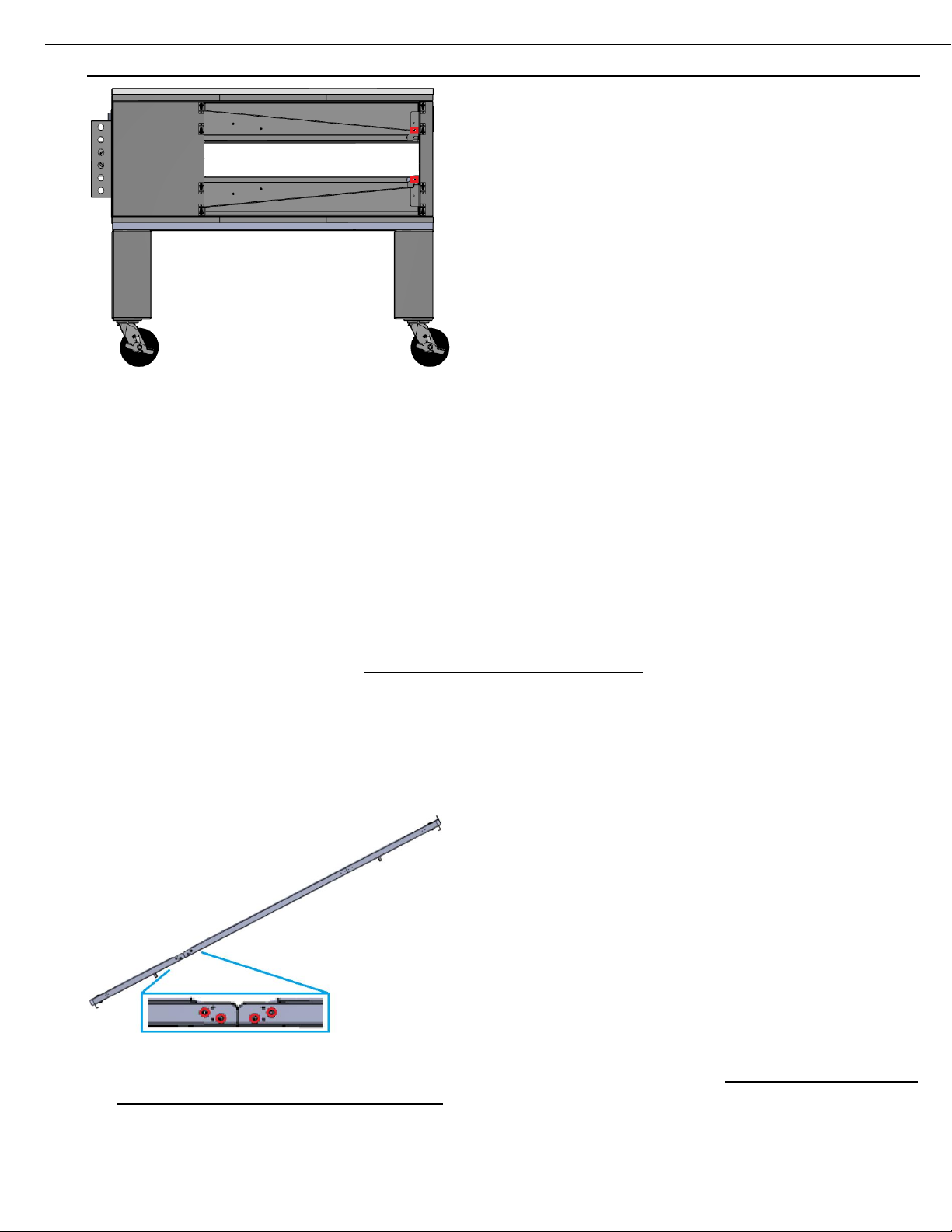
CONVEYOR INSTALLATION
1. Carefully unfold the oven belt on a flat surface.
2. Connect the sections of frame using the attached brackets, the 1/4-20 bolts and 7/16” nuts. You
will find this hardware in a small canvas bag, attached to each belt.
3. With the belt correctly assembled, move it to the installation area.
4. The belt will be installed from the right side (control cabinet side) of the oven. This is a 2-person
job and careful communication must be used to avoid pinching fingers. It is recommended that
the oven wheels be locked at this point.
5. Guide the conveyor into the oven, with a person on each of the long sides.
6. Tilt the belt as needed to prevent brackets from hitting or dragging across the end plugs or oven
interior.

EDGE-1830 / EDGE-2440 / EDGE-3240 / EDGE-2460 / EDGE-3260 / EDGE-3860 / EDGE-4460 / EDGE-3270
Installation and Operating Manual
Original Instruction Manual 11 Rev 1.0, July 2019
7. When the conveyor is sufficiently started into the oven, shift manpower locations to the short sides
of the belt. One person will feed the tilted belt in the oven, while the other receives the belt. Again,
communication is key during this process for safety.
8. The belt should be extended about 6 additional inches to the left, which will allow enough slack to
install the conveyor drive chain(s) to the conveyor motor sprocket(s) and conveyor motor
sprocket(s).
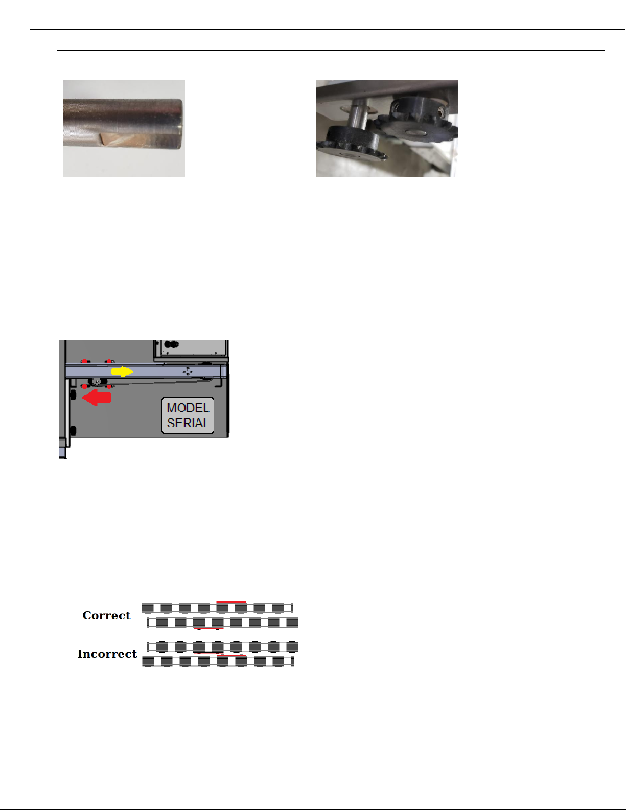
9. Please look over the conveyor drive system and install these chains using the following
information:
The conveyor is driven by a motor, sprocket, and chain system. The sprocket(s) located on the motor(s) are keyed and contain (2)
Allen Setscrews. This does not prevent the sprocket from moving IN or OUT of the shaft in the event a handling situation occurs during
shipping or installation. Adjustment may be required for alignment during the installation process
S T A N D A R D C O N V E Y O R O V E N S
Motor Shaft: Single Conveyor: Setscrew on Key and Flat
The Motor Sprocket is flush with the Shaft of a Conveyor Motor.
The Conveyor Belt will have a single Drive Sprocket. The Sprocket is seated on a Conveyor Shaft, which much like the Drive Motor
shaft, has a Flat area.
Conveyor Shaft: Single Conveyor: Setscrew on Flat and Round
Drive Sprocket is flush with the Shaft of a Standard Conveyor Shaft.
The sprocket on the conveyor shaft is a point of maintenance. Periodic inspection must be performed to ensure the setscrews have
not become loose and have not moved from the flat during use. This often occurs during oven cleaning.
S P L I T - B E L T C O N V E Y O R O V E N S
Front Motor (3 bolts): Setscrew on Key and Flat Rear Motor (4 bolts): Setscrew on Key and Round
The Front Motor Sprocket is flush with the Shaft
Rear Motor Sprocket is aligned with the back end of the Flat.
The Conveyor Belt will have a pair of Drive Sprockets. Each Sprocket is seated on a Conveyor Shaft, which much like the Drive Motor
shaft, has a Flat area.
EDGE-1830 / EDGE-2440 / EDGE-3240 / EDGE-2460 / EDGE-3260 / EDGE-3860 / EDGE-4460 / EDGE-3270
Installation and Operating Manual
Original Instruction Manual 12 Rev 1.0, July 2019
Conveyor Shaft: Offset Sprockets: Setscrew on Flat and Round
Each Conveyor Drive Sprocket is flush with the end of the Conveyor Shaft.
The sprocket on the conveyor shaft is a point of maintenance. Periodic inspection must be performed to ensure the setscrews have
not become loose and have not moved from the flat during use. This often occurs during oven cleaning.
10.Ensure the 7/16” conveyor motor bolts are loosened to allow the conveyor motor to slide back and
forth for adjustment. 4 bolts for rear or single motor, [3 bolts for split-belt conveyors].
11.Install the chain [or longest] chain from the [back] motor sprocket to the [left most] conveyor
sprocket.
12.Lift and pull the conveyor toward the right, allowing it to be fully seated in the oven. This action
will draw the loosened conveyor motor forward.
13.Adjust the tension of the chain so that ¼" of sag exists. A correctly adjusted [long] chain will have
just enough slack to allow the belt to be lifted and pushed into the oven. This allows for easy
removal later, when cleaning is required.
NOTE REGARDING SPLIT-BELT CHAIN INSTALLATION
14.It is important, when installing chains for a Split-Belt oven to position the ‘Master-Links’ away from
one another. Failure to do so WILL cause clearance problems, Belt Jam errors and can cause
damage to the conveyor system.
15.Tighten the (4) 7/16” bolts of the rear conveyor motor when adjustment is correct.
16.For split-belt ovens, thefront, short chain is installed by adjusting the motor forward, then attaching
the chain around the sprockets.
17.Adjust the motor back, to remove the slack, tighten the (3) 7/16” bolts when correct. These (3)
bolts will be loosened each time the conveyor is removed to clean the oven. The belt will not lift
and shift into the oven with the short chain attached.

EDGE-1830 / EDGE-2440 / EDGE-3240 / EDGE-2460 / EDGE-3260 / EDGE-3860 / EDGE-4460 / EDGE-3270
Installation and Operating Manual
Original Instruction Manual 13 Rev 1.0, July 2019
STANDARD ACCESSORIES
The standard accessories supplied with your new oven(s) may include:
- Heat Shields (For stacked ovens)
- Chain Guards
- Perforated Crumb Pans (For middle or top ovens)
- Non-Perforated Crumb Pans (For lower or single ovens)
- Belt Stops (For exit side of all ovens)
- Supplemental Columnating Panels (for baking characteristic adjustments)
Additional accessories may come with the oven(s), please refer to the instruction sheet packaged with
those parts.
Heat Shields
Heat shields are required when stacking 2 or 3 ovens. The heat shields deflect escaping heat, from
the oven, away from the underside of the Control Cabinet. The heat shield is secured using (2) of the
existing Phillips fasteners which secure the Control Cabinet lid.
Chain Guards
Chain guards are intended to prevent access to the moving drive chain of the conveyor system. This
guard installs between the conveyor belt and the control cabinet. A Phillips fastener is then installed
through the guard, into the side of the control cabinet, to secure the guard from accidental removal.

EDGE-1830 / EDGE-2440 / EDGE-3240 / EDGE-2460 / EDGE-3260 / EDGE-3860 / EDGE-4460 / EDGE-3270
Installation and Operating Manual
Original Instruction Manual 14 Rev 1.0, July 2019
Crumb Pans
Crumb pans are provided for sanitation purposes. Single ovens or BOTTOM ovens in a stack will
have SOLID crumb pans installed under the end of the belts. These pans simply slide into place,
using the brackets provided on the underside of the belt. Stacked ovens, other than the bottom, use
Perforated Crumb pans only. NEVER install solid crumb pans on a middle or top oven. Doing so will
cause trapped heat under the conveyor which will push out under the control system, potentially
damaging it. Heat damage is not warrantied.
Belt Stops
There are a few styles of Belt Stops. The typical variety simply flip over the end of the conveyor belt
on the exit side of the belt travel. This is an aide in preventing finished products from falling on the
floor in a busy shop. Some variations of this include Take-Off-Trays, which extend the take-off area.
Other styles are Side Stops, which help keep product from rolling out the side as well. All styles slip
over the belt at an angle and then are pulled flush to seat them.
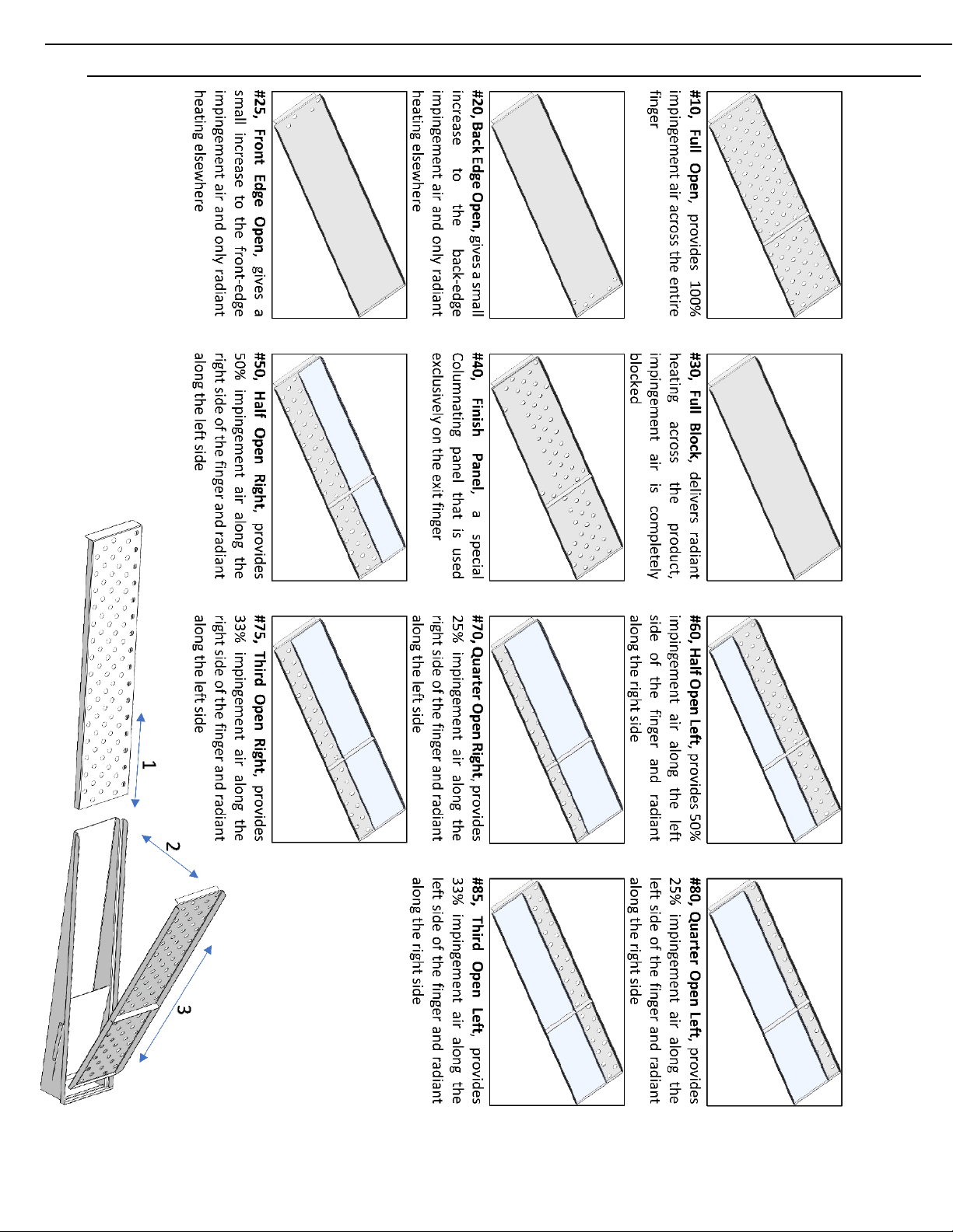
Columnating Panels
Additional Columnating panels may also be provided with the oven. Ovens are built with a universal
pattern pre-installed. Additional panels are provided to alter the oven baking characteristics, to best
match the product being baked. Columnating panels are used within the oven finger housing. For
additional information, please see the section “FINGER ASSEMBLIES”.
FINGER ASSEMBLIES
1. All EDGE ovens are shipped with a total of eight (8) finger assemblies per oven. Each finger
assembly consists of three (3) parts:
A) Finger Housing
B) Columnating Panel (various configurations)
C) Finger Cover
Figure 8
B
C
A
A
B
C

EDGE-1830 / EDGE-2440 / EDGE-3240 / EDGE-2460 / EDGE-3260 / EDGE-3860 / EDGE-4460 / EDGE-3270
Installation and Operating Manual
Original Instruction Manual 15 Rev 1.0, July 2019
2. The finger pattern of the oven determines the baking characteristics. Once the finger pattern is
known, mark the decal on the control cabinet. All bottom fingers are fully open, using #10
Columnating panels.
3. Working from the control side of the oven, set the first pair of upper and lower finger assemblies
into place by sliding them into the oven with the narrow end slightly raised (to avoid the front finger
holders). Align the wider (open) end of the finger over the finger opening in the plenum wall and
lower the narrow end into the front finger holder. (Figure 9)
Figure 9
4. Repeat step 3 until all eight (8)-finger assemblies have been installed.
EDGE-1830 / EDGE-2440 / EDGE-3240 / EDGE-2460 / EDGE-3260 / EDGE-3860 / EDGE-4460 / EDGE-3270
Installation and Operating Manual
Original Instruction Manual 16 Rev 1.0, July 2019

EDGE-1830 / EDGE-2440 / EDGE-3240 / EDGE-2460 / EDGE-3260 / EDGE-3860 / EDGE-4460 / EDGE-3270
Installation and Operating Manual
Original Instruction Manual 17 Rev 1.0, July 2019
FINAL CONNECTIONS
Final installation and connection of gas and electrical should be performed by a licensed plumber and
electrician. Gas pressures, (inlet and the high/low fire) of this oven will need to be checked and set
to specifications listed in this manual. Electrical supply to this oven must be inspected and meet the
specifications listed in this manual.
The electrical supply is to be directly connected within the side mounted electrical box. Remove the
3 lid screws to access these connection points. Ensure the earth ground is properly terminated to the
marked bonding point.
WARNING
Always check for leaks after making any gas supply piping connections or performing any
service on the oven.
WARNING
To prevent damage to the oven and personal injury or death, the voltage, phase and grounding
of the electrical supply must be inspected and verified prior to energizing.
RESTRAINT CABLE
IMPORTANT
OVENS EQUIPPED WITH CASTERS:
(1) Adequate means must be provided to limit movement of the appliance without depending
on the connector, quick-disconnect device, or associated piping to limit appliance
movement.
(2) The restraining device must be attached to the mounting eye located on the left side of
the oven base assembly.
All EDGE ovens are equipped with casters, and a restraint cable must be installed to limit movement
of the oven without straining the gas or electrical connections. One end of the restraint cable is
anchored to the wall, and the other end is anchored to the mounting eye located on the left side of the
oven base assembly.
Ensure that the restraint cable limits movement of the oven so that no strain is placed on either the
gas supply quick-disconnect fitting or the electrical power cord.
After connecting the restraint cable, move the oven into its final position and lock the casters.
Whenever any maintenance or service is performed and the restraint must be disconnected, ensure
that it is reconnected as soon as the oven is returned to its normal installed position.
Other manuals for EDGE-1830
4
This manual suits for next models
7
Table of contents
Other Edge Kitchen Appliance manuals


