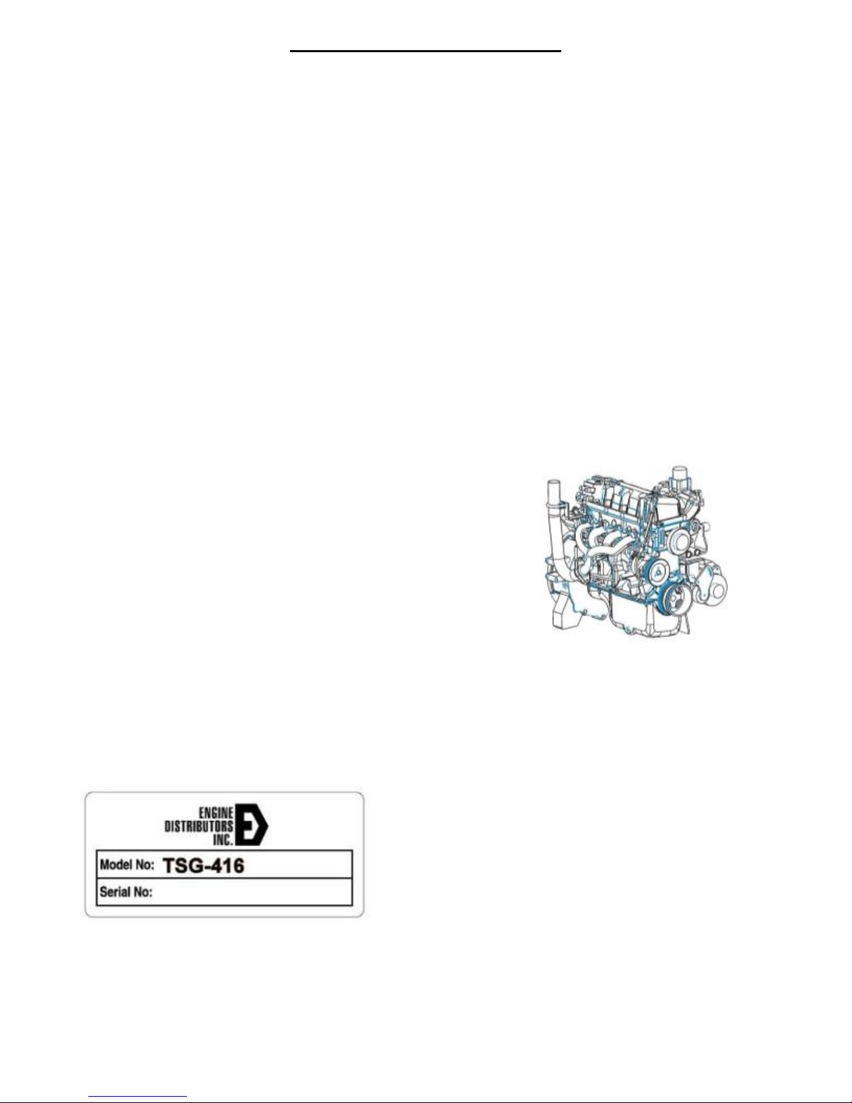
TSG‐416GENERALINFORMATION
01‐3
GENERAL INFORMATION
Introduction
This section covers various engine tests, adjustments,
service procedures and cleaning/inspection procedures.
Engine assembly and service specifications appear at
the end of the Section 02.
For engine disassembly, assembly, installation,
adjustment procedures and specifications, refer to
Section 02.
This engine incorporates a closed-type crankcase
ventilation system.
To maintain the required performance level, the fuel
system, ignition system and engine must be kept in good
operating condition and meet recommended adjustment
specifications.
Before replacing damaged or worn engine components
such as the crankshaft, cylinder head, valve guide,
valves, camshaft or cylinder block, make sure part(s) is
not serviceable.
WARNING: TO AVOID THE POSSIBILITY OF
PERSONAL INJURY OR DAMAGE, DO NOT
OPERATE THE ENGINE UNTIL THE FAN BLADE HAS
FIRST BEEN EXAMINED FOR POSSIBLE CRACKS
OR SEPARATION.
CAUTION: Use of abrasive grinding discs to remove
gasket material from the engine sealing surfaces
during repair procedures can contribute to engine
damage and wear. Airborne debris and abrasive grit
from the grinding disc may enter the engine through
exposed cavities causing premature wear
and eventual engine damage.
Engine Distributors Inc. (EDI) does not recommend
using abrasive grinding discs to remove engine gasket
material. Use manual gasket scrapers for removing
gasket material from the engine sealing surfaces.
Take added care to prevent scratching or gouging
aluminum sealing surfaces.
Safety Notice
There are numerous variations in procedures,
techniques, tools and parts for servicing equipment, as
well as in the skill of the individual doing the work. This
manual cannot possibly anticipate all such variations and
provide advice or cautions as to each. Accordingly,
anyone who departs from the instructions provided in
this Manual must first establish that neither personal
safety nor equipment integrity are compromised by the
choice of methods, tools or parts.
Notes, Cautions, and Warnings
As you read through the procedures, you will come
across NOTES, CAUTIONS, and WARNINGS. Each one
is there for a specific purpose. NOTES gives you added
information that will help you to complete a particular
procedure. CAUTIONS are given to prevent you from
making an error that could damage the equipment.
WARNINGS remind you to be especially careful in those
areas where carelessness can cause personal injury.
The following list contains some general WARNINGS
that you should follow when you work on the equipment.
GENERAL WARNINGS:
TO HELP AVOID INJURY:
ALWAYS WEAR SAFETY GLASSES FOR EYE
PROTECTION.
USE SAFETY STANDS WHENEVER A
PROCEDURE REQUIRES YOU TO BE UNDER THE
EQUIPMENT.
BE SURE THAT THE IGNITION SWITCH IS
ALWAYS IN THE OFF POSITION, UNLESS
OTHERWISE REQUIRED BY THE PROCEDURE.
SET THE PARKING BRAKE (IF EQUIPPED) WHEN
WORKING ON THE EQUIPMENT. IF YOU HAVE AN
AUTOMATIC TRANSMISSION, SET IT IN PARK
(ENGINE OFF) OR NEUTRAL (ENGINE ON)
UNLESS INSTRUCTED OTHERWISE FOR A
SPECIFIC OPERATION. PLACE WOOD BLOCKS
(4”X 4” OR LARGER) TO THE FRONT AND REAR
SURFACES OF THE TIRES TO PROVIDE
FURTHER RESTRAINT FROM INADVERTENT
EQUIPMENT MOVEMENT.
OPERATE THE ENGINE ONLY IN A WELL
VENTILATED AREA TO AVOID THE DANGER OF
CARBON MONOXIDE.
KEEP YOURSELF AND YOUR CLOTHING AWAY
FROM MOVING PARTS WHEN THE ENGINE IS
RUNNING, ESPECIALLY THE FAN BELTS.
TO PREVENT SERIOUS BURNS, AVOID CONTACT
WITH HOT METAL PARTS SUCH AS THE
RADIATOR, EXHAUST MANIFOLD, TAIL PIPE,
CATALYTIC CONVERTER AND MUFFLER.
DO NOT SMOKE WHILE WORKING ON THE
EQUIPMENT.
ALWAYS REMOVE RINGS, WATCHES, LOOSE
HANGING JEWELRY, AND LOOSE CLOTHING
BEFORE BEGINNING TO WORK ON THE
EQUIPMENT. TIE LONG HAIR SECURELY BEHIND
THE HEAD.
KEEP HANDS AND OTHER OBJECTS CLEAR OF
THE RADIATOR FAN BLADES. ELECTRIC
COOLING FANS CAN START TO OPERATE AT
ANY TIME BY AN INCREASE IN UNDERHOOD
TEMPERATURES, EVEN THOUGH THE IGNITION
IS IN THE OFF POSITION. THEREFORE, CARE
SHOULD BE TAKEN TO ENSURE THAT THE
ELECTRIC COOLING FAN IS COMPLETELY
DISCONNECTED WHEN WORKING UNDER THE
HOOD.