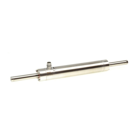
Simu DMI6 Hz User manual

1/3
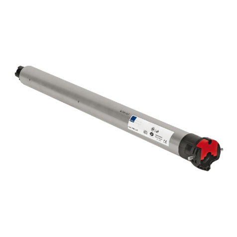
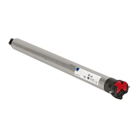
DMI5Hz - DMI6Hz MOTORS
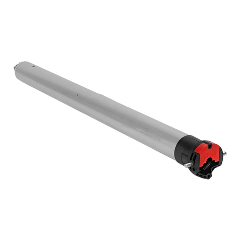
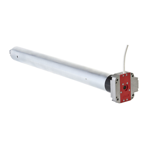
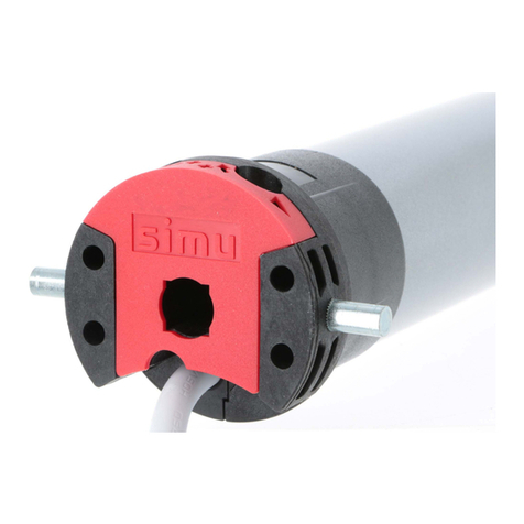
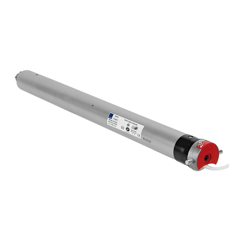
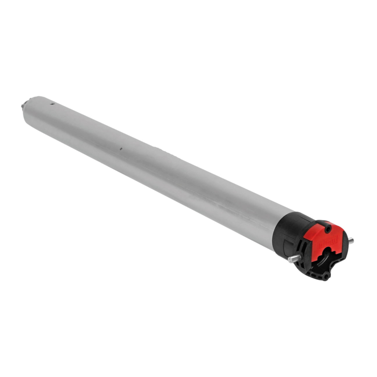
Tubular operators with integrated radio and manual override for blinds, awnings & roller shutters
S.A.S. au capital de 5 000 000 €- Z.I. Les Giranaux - BP71 - 70103 Arc-Les-Gray CEDEX - RCS GRAY B 425 650 090 - SIRET 425 650 090 00011 - n° T.V.A CEE FR 87 425 650 090
®
5047058A
IMPORTANT - Review instruction throughly before installing Hz motors
USA
- This device complies with part 15 of the FCC Rules. Operating is subject to the following two conditions:
(1) This device may not cause harmful interference.
(2) This device must accept any interference received, including interference that may cause undesired operation.
- Caution: Changes or modifications not expressly approved by the party responsible for compliance could void the user’s authority to operate the equipment.
1ASSEMBLY
1.1 - TUBE PREPARATION
Warning: do not cut or drill the tube with the motor
installed.
- Cut the tube to the required length.
- Remove all burrs from the tube.
- If using a round tube, cut a notch (D wide by C long)
into one end of the tube.
- On round tubes measure length (A) and drill 4 holes
around the tube. For octagonal tubes 1 hole is
sufficient.
1.2 - INSTALLING THE TUBULAR MOTOR
1- Fit the adaptor over the crown. Align the slot in the
adaptor with the raised key and firmly fit the adaptor
over the crown. A crown adaptor is not necessary with
47mm (2”) tubes.
2- Snap the drive wheel onto the drive shaft. Screw on
the drive stop if needed (60 Nm+ operators).
3- Slide the tubular motor into the tube. Do not force or
hammer on the head of the motor. If the motor does
not insert smoothly, remove the motor and file smooth
the edge of the tube. On round tubes confirm the
raised key on the crown fits snugly into the cut slot on
the end of the tube.
4- Secure the drive wheel to the tube. For the composite
drive, use four 3/16” dia. steel pop rivets or four 1/4”
dia. screws with steel grade SAE 5 or higher. For the
aluminum drive, use the three 5mm X 6mm cheese
head screws provided.
1.3 - MOUNTING THE TUBULAR MOTOR
The Hz DMI motor uses standard DMI accessories.
- Mount the motor as shown using only SIMU
accessories.
- Mount the motor heads at least 8” apart from each
other to prevent RF interference.
- Always install the power cable with a drip loop to
prevent water penetration.
- SIMU motors conform to IP44 requirements and as such
must be protected against direct weather elements such
as rain, sleet, ...etc. Failure to do so could result in
voiding the warranty.
12 TRANSMITTERS MAXIMUM 1ft < d1 < 65ft d2 > 8 inches
WARNING
AØB
D
C
AØB Ø min.
T min.
Ø 3/16
STEEL SAE5 or higher
1.1
Ø 1/4
For Composite Drive
For the Aluminum
Drive use the 5mm X
6mm screws supplied
with the drive
4 X
or
4 X
754
754
For the aluminum drive A is 20mm less than shown
840
840
-
-
26 4.2
-
8
-
36
mm
ABCD
Ø / T min.
5
47
60 5
DMI5Hz
120V / 60Hz
DMI6Hz
120V / 60Hz
12
43
1.2
1.3

2WIRING
2.1 - DMI Hz PERMANENT WIRING (shutter, shade or awning)
Warning: All wiring must conform to the National Electric Code and local
codes.
- (1) The motor must be installed with a drip loop to prevent water intrusion.
- (2) Connect the motor to power using a listed junction box with appropriate
cable strain reliefs.
- It is recomended a method of power disconnect for each motor be placed
within sight of the motor to cut power during servicing and facilitate
reprogramming.
- Do not use the motor cable to penetrate building walls. Connect the motor
to power in a listed junction box and from the listed junction box run power
in the manner proscribed by NEC. and local codes.
2.2 - DMI Hz PLUG-IN WIRING (shade or awning)
Warning: All wiring must conform to the National Electric Code and local
codes.
- (1) The motor must be installed with a drip loop to prevent water intrusion.
- (2) If used outdoors, a GFCI receptacle with an outdoor cover is required.
- Do not use the motor cable to penetrate building walls.
4PROGRAMMING
3COMPATIBLE TRANSMITTERS
OPERATOR
WIRING CHART
MOTOR
CABLE
POWER
120VAC
BLACK
WHITE
GREEN
HOT
NEUTRAL
GROUND
2.1
MOTOR
CABLE
POWER
120VAC
BLACK
WHITE
GREEN
HOT
NEUTRAL
GROUND
2.2
OPERATOR
WIRING CHART
4.1 - WAKING UP THE MOTOR.
Before programming, changing direction of rotation, setting the limits, etc…you must wake the motor up. If using a multi-channel
transmitter, confirm you are on the desired channel. Press and hold the UP and DOWN together until the motor gives a short up/down
bounce. The motor is now awake.
4.2 - DIRECTION OF ROTATION.
You must check the direction of rotation before programming. If the direction of rotation is not correct, press and hold the STOP Button
until the motor gives a short up/down bounce. Confirm the direction of rotation is now correct.
4.3 - PROGRAMMING A TRANSMITTER CHANNEL TO A MOTOR.
If using a multi-channel transmitter, confirm you are on the desired channel. Press the Program Button and the motor will give a short
up/down bounce. Confirm the transmitter now controls the motor. A short push on the UP of DOWN button should make the motor run
until you stop it or the motor stop at its limits. You should not have to hold the button down.
4.4 - ADDING ADDITIONAL TRANSMITTERS (CHANNELS) TO THE MOTOR.
Use the transmitter that currently controls the motor and confirm it is on the correct channel. Press and hold the Program Button until the
motor gives a short up/down bounce. Confirm transmitter is on the channel you wish to add and press the Program Button. The motor
will give a short up/down bounce. The new channel is now added. Repeat for any additionnal transmitter channels you wish to add.
4.5 - DELETING A TRANSMITTER CHANNEL TO A MOTOR.
Use a transmitter that currently controls the motor and confirm it is on the correct channel to control the motor. Press and hold the
Program Button until the motor gives a short up/down bounce. Press the Program Button of the second transmitter until the motor gives a
short up/down bounce. The second transmitter is now deleted.
4.6 - CLEARING THE MEMORY OF OLD TRANSMITTERS AND ADDING NEW TRANSMITTERS.
If all a motor transmitters are lost or damaged it is possible to clear the old memorized codes from memory and add the new transmitter.
Perform a double power cut in the following sequence:
1- Power off for at least 8 seconds
2- Power on for 8 seconds
3- Power off for at least 8 seconds
4- Power on. The motor will try and run for 5 seconds but will not run past its limits.
The motor is now in a temporary mode for 2 minutes. NOTE: this is not the “factory mode”. Press and hold the Program Button of
any unmemorized transmitter for more than 8 seconds. When the motor gives a short up/down bounce release the button. The memory
of the motor’s receiver is now cleared of the old transmitters and the new transmitter has been added. If a motor or motors are entered
into temporary programing mode by mistake it can be cancelled by pressing for a second on the UP, STOP or DOWN of any transmitter
that motor has memorized. The motor will also return to normal operating mode if left for 2 minutes.
Hand Held TransmitterWall switch Transmitter Decorator Wall Switch Hz Timer
single channel five channel single channel five channel
PROGRAM BUTTON
(back of transmitter)
PROGRAM BUTTON
(back of transmitter)
PROGRAM BUTTON
(side of transmitter)
PROGRAM BUTTON
2/3

5.1 - Identify which limit adjustment screw controls the up limit and which controls the down limit (see above diagrams). It is important to note
that the arrows by the limits adjustments screws refer to the tube’s rotation. Thus if the material comes off the tube on the back side and
you are adjusting the limits from the side that the motor cable is not on (as per diagrams 2), the limit adjustment screw with the arrow
facing up controls the down limit and vice-versa.
5.2 - Turning an adjustment screw positive (+) will increase the maximum travel in the direction that it controls and turning it negative (-) will
decrease the maximum travel. For the adjustment screws on the side without the motor cable, turning clockwise is positive (+) and
counterclockwise is negative (-). For the adjustment screws on the side with motor cable, turning clockwise is negative (-) and
counterclockwise is positive (+).
5.3 - To set a limit, run the motor in the selected direction.
5.4 - If the motor stops on its own before reaching the desired stop, turn the appropriate limit screw positive (+). Every 2 or 3 turns of the limit
adjustment screw will allow the motor to travel about 1 inch further. After every few turns of the limit adjustment screw use the control
switch to move the motor to the new limit position. If the motor does not stop on its own before reaching the desired stop, go to step 5.6.
5.5 - When you are approximately at the desired stop, use the control switch to run the motor away from the limit 2 or 3 feet and then back. This
will allow you to see precisely where the limit is set. Make small adjustments and repeat.
5.6 - If the motor does not stop on its own at least 6 inches before the desired limit position, stop the motor with the control switch. Then turn
the adjustment screw in the negative (-) direction. Confirm that the motor is stopped at the limit and set the limit as in step 5.4 and 5.5. If
the motor is not stopped at the limit, continue turning the limit adjustment screw (up to 120 turns may be required).
NOTE: The motor has a built-in thermal cut-off. If after several minutes of use the motor will not run in either direction allow the motor to cool
approximately 20 minutes.
3/3
5SETTING THE LIMITS
4.7 - RETURNING TO ORIGINAL FACTORY MODE (deleting all transmitters).
NOTE: When the motor is in factory mode is the only time the direction of rotation can be changed. To return the motor to Factory Mode,
perform a double power cut as described in section 4.6. Press and hold for 8 seconds the Program Button of an already recorded
transmitter. The motor will give a short up/down bounce. Release the Program Button. The motor is now in factory mode. To wake the
motor up press UP & DOWN until the motor gives a short up/down bounce. All transmitters are cleared from memory, the control will be
in a momentary fashion (motor will move only as long as the transmitter button is held down).
NOTE: If you did not use a transmitter that was memorized by the motor, you will have to repeat the process a second time.
4.8 - TROUBLESHOOTING.
- Motor goes up when down is pressed: go to step 4.2 “setting direction of rotation”.
- Can not change the Direction of Rotation: Confirm the motor is in “Factory Mode” (it only runs as long as the transmitter button is held
down). If it is not, go to step 4.7
- Lost transmitter: Go to step 4.6 to clear old transmitters from memory and add new transmitter.
- The motor will not react to any transmitter: Confirm the motor has power to it. Make sure the motor is awake by pressing UP and DOWN
together until the motor gives a short up/domn bounce. IF it does not work, cut power for 3 seconds and try again. If the motor still will not
react to the transmitter, follow the instructions in step 4.6.
- The motor stops responding to the transmitter after a power loss: The motor was still in factory mode. Follow steps 4.1, 4.2 and 4.3 above. If
the Program Button is not pressed as in step 4.3, the motor is not programmed.
- The motor only runs as long as the transmitter button is held down: The motor has not been programmed. Go to step 4.2 and 4.3 above.
DOWN LIMIT ADJUSTMENT SCREW
MATERIAL ROLLS DOWN ON SAME SIDE AS LIMITS
1
UP ADJUSTMENT SCREW
MATERIAL ROLLS DOWN ON OPPOSITE SIDE AS LIMITS
2
UP LIMIT ADJUSTMENT SCREW DOWN LIMIT ADJUSTMENT SCREW
LIMIT ADJUSTMENT SCREWS ON OPPOSITE SIDE FROM MOTOR CABLE
UP LIMIT ADJUSTMENT SCREW
MATERIAL ROLLS DOWN ON SAME SIDE AS LIMITS
DOWN LIMIT ADJUSTMENT SCREW
3
MATERIAL ROLLS DOWN ON OPPOSITE SIDE AS LIMITS
4
DOWN LIMIT ADJUSTMENT SCREW
MOTOR CABLE MOTOR CABLE
UP LIMIT ADJUSTMENT SCREW
MOTOR CABLE MOTOR CABLE
LIMIT ADJUSTMENT SCREWS ON SAME SIDE FROM MOTOR CABLE
This manual suits for next models
1
Other Simu Engine manuals
