EDI 242L User manual

THE MODEL 242L DC ISOLATOR UNIT IS DESIGNED AND MANUFACTURED IN THE USA BY
EBERLE DESIGN INC., PHOENIX, ARIZONA, AN ISO 9001:2015 REGISTERED COMPANY.
U.S. PATENT NO. 7,855,893
© COPYRIGHT 2015 EDI
SERIAL NUMBER: 1506XXXXX and up
PCB Issue A, 110-0244-001
REVISION: JUNE 2015
pn 888-2420-001
STATE OF CALIFORNIA
MODEL 242L
DC ISOLATOR UNIT
OPERATIONS MANUAL

Table of Contents
1.1 Glossary......................................................................................................1
1.2 General Description.....................................................................................1
1.3 General Characteristics...............................................................................1
1.4 Installation and Adjustments .......................................................................2
1.4.1 Minimum Output Pulse.........................................................................2
1.4.2 Input Polarity........................................................................................2
1.5 Theory of Operation ....................................................................................2
1.5.1 System Description..............................................................................2
1.5.2 Input Circuit..........................................................................................3
1.5.3 MCU Circuit..........................................................................................3
1.5.4 Output Circuit.......................................................................................3
1.5.5 Display and Switch Circuit....................................................................3
1.5.6 Power Supply Circuit............................................................................3
1.6 Maintenance................................................................................................3
1.6.1 Trouble Analysis ..................................................................................3
1.6.2 Trouble Shooting Sequence.................................................................4
1.7 Specifications..............................................................................................4
1.7.1 Construction.........................................................................................4
1.7.2 Mechanical...........................................................................................4
1.7.3 Environmental......................................................................................4
1.7.4 Electrical ..............................................................................................4
1.7.5 Timing..................................................................................................5
1.7.6 Connections.........................................................................................5
1.8 Parts List and Schematic.............................................................................6

Model 242L Operations Manual
Eberle Design Inc. Page 1
1.1 GLOSSARY
A - Ampere
oC - Celsius
Component - Any electrical or electronic device
DC - Direct Current
Firmware –Program code embedded into a microcontroller unit
Hz - Hertz
IC - Integrated Circuit
Jumper - A means of connecting/disconnecting two or more conductive by soldering/desoldering a
conductive wire or by PCB post jumper
LED - Light Emitting Diode
LOGIC - Negative Logic Convention (Ground True) State
mA - milliAmpere
ms - millisecond
MCU - Micro Controller Unit or microcontroller unit
MOV - Metal Oxide Varistor
Opto-coupler –An integrated circuit that provides electrical isolation
PCB - Printed Circuit Board
RMS - Root-Mean-Square
s –second
Schmitt Circuit –a circuit that provides hysterisis in the threshold
SW –Switch
uF - microfarad
VAC - Voltage Alternating Current
VDC - Voltage Direct Current
1.2 GENERAL DESCRIPTION
The Eberle Design Model 242L is a dual channel DC Isolator unit designed to meet Caltrans
specifications TEES 2009 including Errata #2 (December 2014). The isolator unit occupies one position
of a 170 standard input file. The isolator unit card incorporates a double-sided 44 pin edge connector
for the connection of power, input, and output signals. Each channel has individual front panel controls
for testing the operational mode, and high intensity front panel LEDs which are used to indicate the
output state. Outputs are optically-isolated solid-state transistors. The Model 242L is powered from the
24VDC Cabinet Power Supply and does not require AC Line.
1.3 GENERAL CHARACTERISTICS
Each channel of the Model 242L provides input hysterisis and digital filtering to qualify the input signal.
An input signal must meet the minimum pulse requirements specified in section 1.7.5 in order to
produce a valid output. The output pulse width for both channels can be set to 100 milliseconds
minimum by installing jumper “100ms” (J4-A).
Both the input and output circuits have been designed for maximum protectionfrom electrical transients.
The inputs have been designed to withstand the discharge of a 10 uF capacitor charged to +/- 1000
Vdc directly across the input pins, and a discharge of a 10 uF capacitor charged to +/- 2000 Vdc applied
through a source impedance of 5 ohms across the input pins or to Equipment Ground. The outputs are
protected by a transient clamp diode.

Model 242L Operations Manual
Eberle Design Inc. Page 2
The Model 242L handle assembly is made of GE LexanTM Type 121, which is a super durable
polycarbonate resin. The design of this assembly strengthens and protects the whole PCB assembly
much better than conventional metal face plates.
1.4 INSTALLATION AND ADJUSTMENTS
Installation of the unit consists of plugging into the appropriate slot of the Input File and connecting the
assigned inputs to the proper cabinet terminals. The edge connector is keyed to prevent incorrect
installation. Following power-up, a front panel LED test will illuminate both OUT indicators for two
seconds.
1.4.1 MINIMUM OUTPUT PULSE
If desired, the outputpulse width for both channels can be set to 100milliseconds minimumby installing
jumper “100ms” (J4-A).
1.4.2 INPUT POLARITY
The polarity of the input can be inverted such that a closed contact input is False and an open contact
input is True. The input polarity of Channel 1 can be set to invert by installing a jumper into the “CH1
POL” (J4-B). The input polarity of Channel 2 can be set to invert by installing a jumper into the “CH2
POL” (J4-C).
1.5 THEORY OF OPERATION
Reference designators shown are for Channel 1. Reference designators for Channel 2 are shown in
parenthesis.
1.5.1 SYSTEM DESCRIPTION
The sensor circuitry can be broken down into seven major blocks. Each “Input Circuit”block contains
the electrical transient devices and the input biasing circuit. Although the Model 242L has two DC
inputs, a single digital processing section is used to process both inputs.
The microcontroller unit “MCU” Block provides the input voltage threshold and input pulse width filtering
function on both channel 1 and channel 2 DC input circuits.
The MCU then controls the OUTPUT and DISPLAY blocks appropriately. The TEST switches can be
used to force the input to the True state. If the TEST switch is in the ON (locked) or MOM (momentary)
position it will force the output to the asserted (True) state regardless of the input circuit state. The
TEST switches are processed through the MCU for pulse width input and output requirements.
Valid output calls are made via optically isolated solid state transistors. Output calls are indicated on
the front panel by means of red LEDs labeled “OUT”.

Model 242L Operations Manual
Eberle Design Inc. Page 3
The Model 242L operating voltage is generated by a high efficiency isolated switching power supply.
The resulting bias voltage supplied to the Input circuits is electrically isolated from both 24VDC Logic
Ground and AC Line Neutral. The VDD supply for the microcontroller and display elements results from
a post regulated 5 Vdc.
1.5.2 INPUT CIRCUIT
Resistors R21, R7, R8, R25, and R19 (R22, R9, R3, R26, and R20) provide the input bias and voltage
scaling circuit. The resulting voltage at U20.3 (U20.4) is then processed by the microcontroller U20.
Gas tube CR2 (CR3) and diode CR 14 (CR16) provides input electrical transient protection.
1.5.3 MCU CIRCUIT
The microcontroller U20 processes the input voltages to perform the voltage threshold and pulse width
filtering functions. All signal processing is performed in the digital domain and controlled by firmware
embedded in the microcontroller. This unit does not rely on analog delay, pulse, or comparator circuits
for processing the input signals.
1.5.4 OUTPUT CIRCUIT
The output driver Q7 (Q8) is isolated from both the AC Mains and the internal GND reference of the
Model 242L by opto-couplers U8 (U9). CR9 (CR6) provides electrical transient protection for the output
driver Q7 (Q8).
1.5.5 DISPLAY AND SWITCH CIRCUIT
The LED indicator DS1 (DS3) for the channel output is driven directly from the microcontroller U20. The
input TEST switch SW1 (SW3) can be used to force the input state to the active status.
1.5.6 POWER SUPPLY CIRCUIT
The main power supply is a fully isolated switching design. The cabinet 24VDC input voltage is used to
drive switching controller U18. The transformer T1 is used by controller U18 to generate the isolated
and regulated 19 VDC input bias voltage VCC that drives the input circuits. The opto-coupler U21 and
reference U25 provide the closed loop feedback to the power supply controller U18 for regulation.
A second regulator U26 generates the 5.0 Vdc internal supply voltage VDD used by the processor
circuit from the 19 VDC bias. Inductor L2, C29, C31, and C24 filter the regulator U26 output to provide
clean VDD to the processor.
1.6 MAINTENANCE
The Model 242L requires no adjustments or preventive maintenance.
1.6.1 TROUBLE ANALYSIS
The following list should be used to trouble-shoot the Model 242L installation. If the Model 242L unit
itself is suspect, see Section 1.6.2 for a complete internal testing sequence.
a. Neither channel responds to DC inputs
a. Power supply fault
The Model 242L requires a nominal 24 Vdc input voltage. The unit will operate at voltages as
low as 10.8 Vdc, however, an input voltage below this may result in the unit entering a reset
state. In this case, the unit will appear to be non-functional.
b. Channel does not detect all inputs

Model 242L Operations Manual
Eberle Design Inc. Page 4
a. Input voltage or pulse width does not meet the requirements of section 1.7.4 or 1.7.5.
Verify that the DC input voltage level is less than the DC Inputs True specification. Verify that
the DC input pulse width is greater than the Input Pulse Width Accept specification.
1.6.2 TROUBLE SHOOTING SEQUENCE
Apply 24 Vdc nominal power to DC POWER pin J1-B referenced to LOGIC GROUND pin J1-A. Connect
a jumper circuit to the DC inputs J1-D (J1-J) and J1-E (J1-K) to simulate the closure of the input
contacts. The following signal measurements are referenced to test point CH1 (CH2).
NOTE: internal test point “GND” is isolated from Logic Ground. Care should be exercised in probing
internal test points.
a. Input Bias Power Supply VCC
Voltage at test point VCC should be 19 1 Vdc with respect to GND.
Possible component faults are: controller U18, CR12, R14, transformer T1, CR30, reference
U25, or opto-coupler U21.
b. Regulated Power Supply VDD
Voltage at test point VDD should be 5 0.2 Vdc with respect to GND.
Possible component faults are: voltage regulator U26, inductor L2, diode CR29.
c. Microcontroller
Possible components at fault are: microcontroller U20.
d. Output Circuit
Output signals are processed by the microcontroller U20 and appear at U20.10 (U20.9) and on
the display LEDs but are not appearing at the output pins.
Possible components at fault are: opto-coupler U8 (U9), output transistor Q7 (Q8).
1.7 SPECIFICATIONS
1.7.1 CONSTRUCTION
Printed circuit boards are double sided copper with plated through holes. Circuit boards are coated for
environmental protection.
1.7.2 MECHANICAL
Height..............................................................................................................................4.50 inches
Width ................................................................................................................................1.2 inches
Depth (excluding handle)...............................................................................................6.875 inches
1.7.3 ENVIRONMENTAL
Storage Temperature Range....................................................................................... -45 to +85 oC
Operating Temperature Range.................................................................................... -34 to +74 oC
Humidity Range (non-condensing)........................................................................0 to 95% Relative
1.7.4 ELECTRICAL
DC Supply Voltage Minimum...............................................................................................10.8 Vdc
DC Supply Voltage Maximum..............................................................................................28.0 Vdc
DC Supply Power Maximum...............................................................................................2.0 Watts
DC Inputs
True (low).............................................................................................................less than 8 Vdc

Model 242L Operations Manual
Eberle Design Inc. Page 5
False (high)...................................................................................................greater than 12 Vdc
Optically Isolated Solid State Outputs
True (low, 50 mA)..............................................................................................less than 1.5 Vdc
False (high)...................................................................................................greater than 16 Vdc
Maximum Leakage Current (high)......................................................................... less than 1 uA
Maximum Current...............................................................................................................50 mA
Collector Voltage Maximum ..............................................................................................50 Vdc
1.7.5 TIMING
Input Pulse Width Reject ............................................................................................less than 5 ms
Input Pulse Width Accept.....................................................................................greater than 10 ms
1.7.6 CONNECTIONS
Edge Connector mates with connector type Cinch 50-44A-30
PIN
FUNCTION
A
Logic Ground
B
DC Supply
D
Input CH 1
E
Input CH 1 Common
F
CH 1 Output Collector
H
CH 1 Output Emitter
J
Input CH 2
K
Input CH 2 Common
L
Equipment Ground
W
CH 2 Output Collector
X
CH 2 Output Emitter

Model 242L Operations Manual
Eberle Design Inc. Page 6
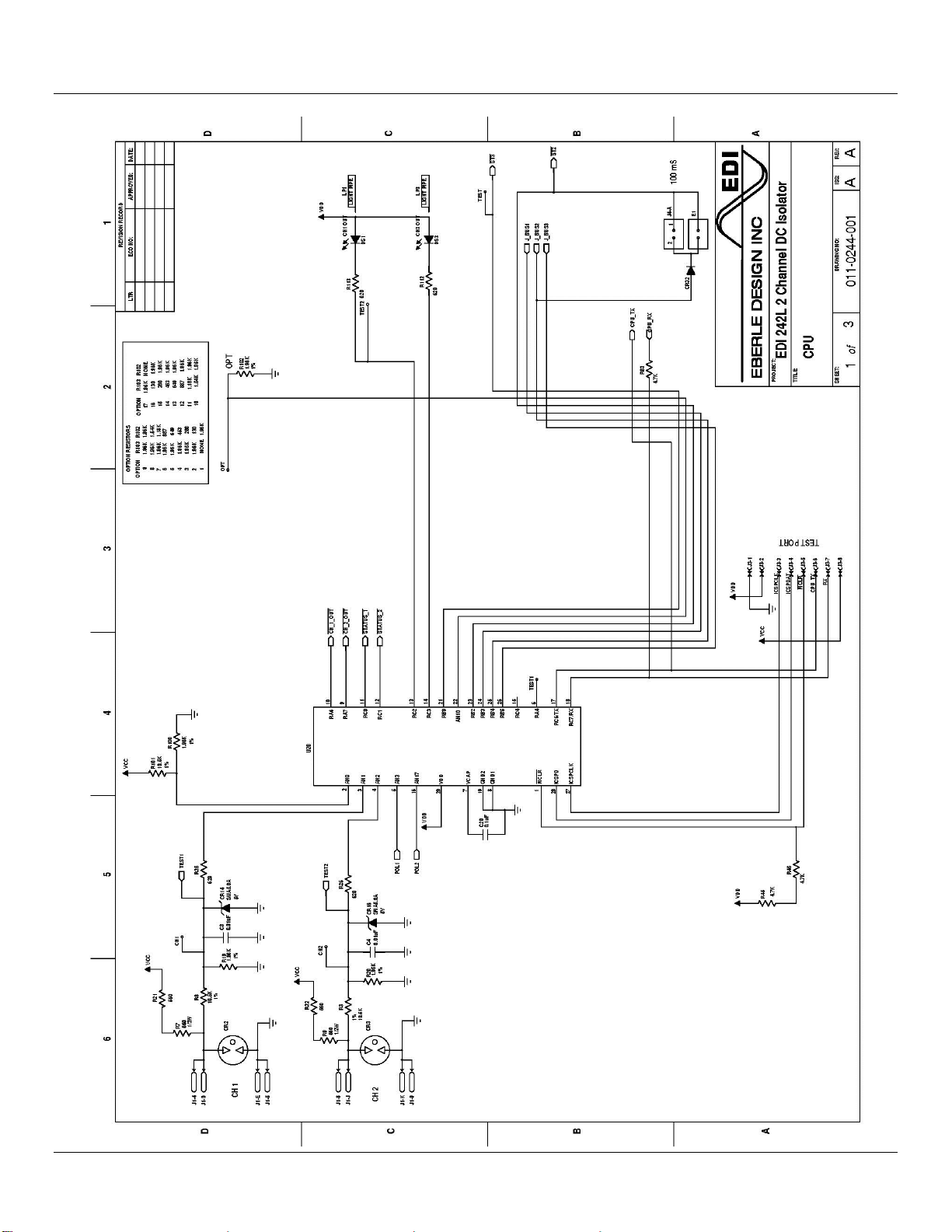
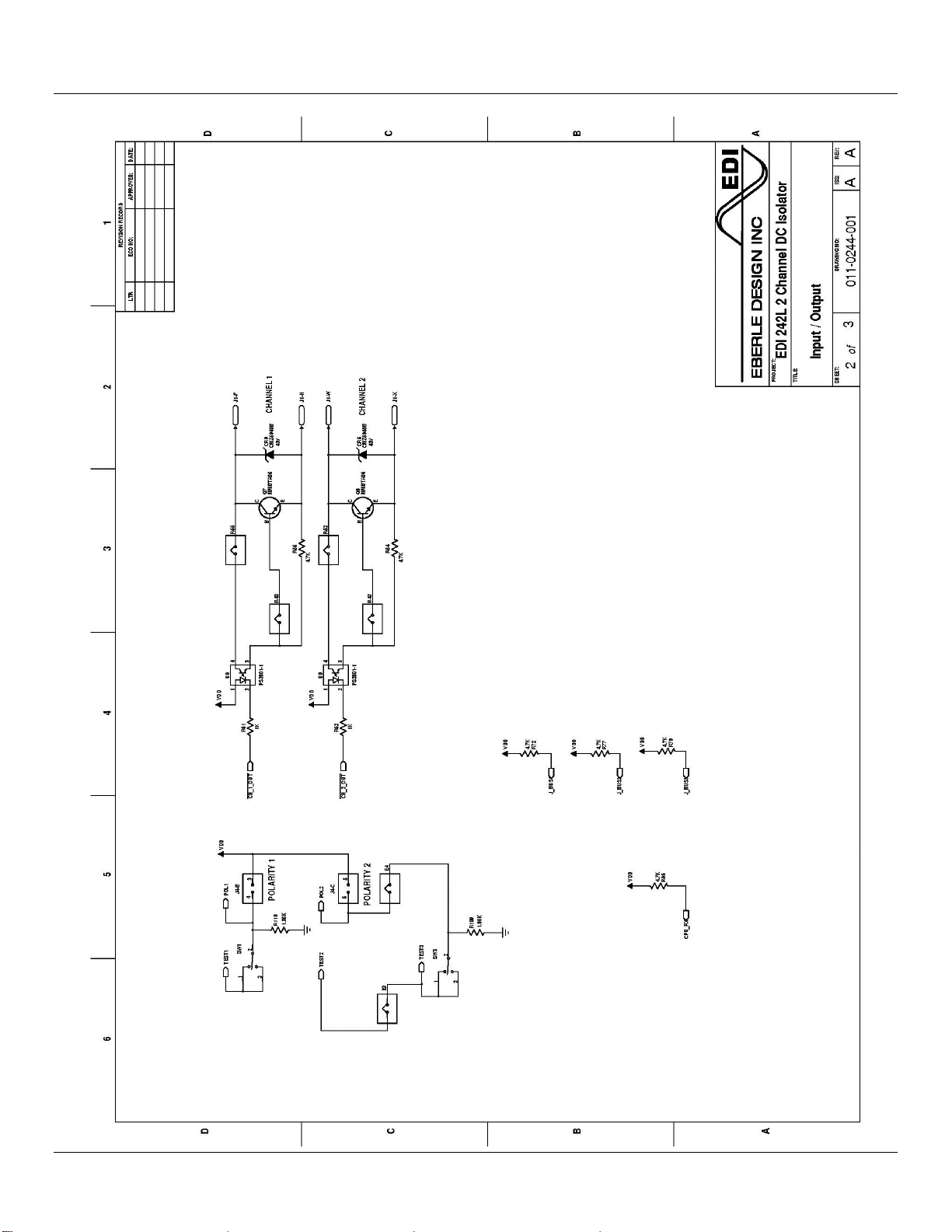
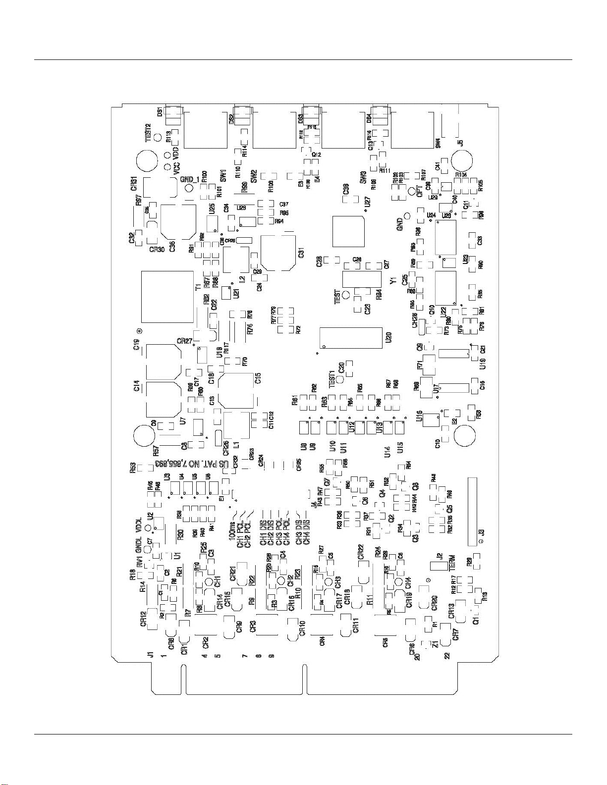
1.8 PARTS LIST AND SCHEMATIC
|------------------------------------------------------------------------------------------------------------------|
|Item|EDI Part Number|Qty|Description |Reference |Manufacturer |
|----+---------------+---+-------------------------------------------------+-------------------+-------------------|
|1 | |1 |(NO COMPONENT) |J1 | |
|2 | |1 |(no component) |J3 | |
|3 | |10 |(NO COMPONENT) |CH1-2 GND GND_1 OPT| |
| | | | |TEST TEST1-2 VCC | |
| | | | |VDD | |
|4 | |1 |(NO COMPONENT) |E1 | |
|5 | |2 | |M1-2 | |
|6 |215-0033-S |2 |RESISTOR, 1/2W, 0.33 OHMS, 5%, 2010 surface mount|R74 R99 | |
|7 |215-0180-S |1 |RESISTOR, 1/2W, 1.8 OHMS, 5%, 2010 surface mount |R14 | |
|8 |215-3310-S |1 |Resistor, 330 OHM, 1/2W, 5%, 2010 surf. mnt. |R117 | |
|9 |215-5610-S |4 |Resistor, 560 OHMS, 1/2W, 5%, 2010 surf. mnt. |R7 R9 R21-22 | |
|10 |215-5620-S |1 |Resistor, 5.6K OHMS, 1/2W, 5%, 2010 surf. mnt. |R82 | |
|11 |251-1052-S |3 |RESISTOR, 1/8W, 10.5K, 1%, 1206 surface mount |R3 R8 R101 | |
|12 |251-1211-S |3 |RESISTOR, 1/8W, 1.21K, 1%, 1206 surface mount |R70 R78 R92 | |
|13 |251-1961-S |7 |RESISTOR, 1/8W, 1.96K, 1%, 1206 surface mount |R19-20 R95 R100 | |
| | | | |R102 R109-110 | |
|14 |251-5901-S |1 |RESISTOR, 1/8W, 5.90K, 1%, 1206 surface mount |R94 | |
|15 |251-8061-S |1 |RESISTOR, 1/8W, 8.06K, 1%, 1206 surface mount |R91 | |
|16 |255-0000-S |6 |RESISTOR, 1/8W, 0 OHMS, 5%, 1206 surface mount |E3-4 R42-43 R52 R55| |
|17 |255-1020-S |3 |RESISTOR, 1/8W, 1K, 5%, 1206 surface mount |R61-62 R88 | |
|18 |255-4310-S |1 |RESISTOR, 1/8W, 430 Ohm, 5%, 1206 surface mount |R87 | |
|19 |255-4720-S |9 |RESISTOR, 1/8W, 4.7K, 5%, 1206 surface mount |R45-46 R54 R56 R72 | |
| | | | |R77 R79 R83 R86 | |
|20 |255-6210-S |4 |RESISTOR, 1/8W, 620 Ohm, 5%, 1206 surface mount |R25-26 R112-113 | |
|21 |261-1200-S |1 |RESISTOR, PULSE RATED, 3/4W, 12 OHMS, 5%, 2010 |R97 |SEI |
| | | |smt | | |
|22 |300-3370-035S |4 |CAPACITOR, ELECTROLYTIC, 330uF, 35V, LOW ESR, |C14 C19 C31 C36 |ILLINOIS |
| | | |20%, SMT | |337AXZ035MD10 |
|23 |320-1010-100S |2 |CAPACITOR, CER.MULT, 100pF, 100V, 5%, NPO,1206 |C32 C34 |Samsung |
| | | |CHIP | |CL31C101JCCNFNC |
|24 |320-1020-050S |2 |CAPACITOR, CER.MULT, 0.001uF, 50V, 10%, 1206 CHIP|C18 C30 | |
|25 |320-1030-100S |2 |CAPACITOR, CER.MULT, 0.01uF, 100V, 10%, 1206 CHIP|C3-4 | |
|26 |320-1040-050S |9 |CAPACITOR, CER.MULT, 0.1uF, 50V, 10%, 1206 CHIP |C9 C20 C22-25 C35 | |
| | | | |C37-38 | |
|27 |320-1060-025S |1 |CAPACITOR, CER.MULT, 10uF, 25V, 10%, 1206 CHIP |C29 |Samsung |

Model 242L Operations Manual
Eberle Design Inc. Page 7
| | | | | |CL31A106KAHNNNE |
|28 |320-2210-050S |1 |CAPACITOR, CER.MULT, 220pF, 50V, 10%, 1206 CHIP |C17 | |
|29 |410-0053-S |2 |DIODE, TRANS. SUPR., SMA5.0A, 5V,SMA |CR14 CR16 |MOTOROLA |
|30 |410-0110-S |2 |DIODE, ULTRAFAST, MURA110T3, 100V,1A, SMA |CR27 CR30 |ON SEMI |
|31 |410-0141-S |1 |DIODE, SCHOTTKY, MBRX140, 40V,1A, SOD123 |CR29 |MMC MBRX140-TP |
|32 |410-1526-S |1 |TRANSORB, SMCJ26A, 26V, 1500W |CR31 |DIODES, INC. |
|33 |410-4005-S |1 |DIODE, S1K, 800 PIV, 1A |CR12 | |
|34 |410-4148-S |1 |DIODE, 1N4148WS, SMT SOD323 |CR32 |DIODES INC. |
|35 |410-4755-S |2 |DIODE, ZENER, CMZ5941B, 1.0W, 5%, 43V,SMA |CR6 CR9 | |
|36 |420-2811-S |3 |OPTOCOUPLER, PS2801-1, 4 PIN SOP |U8-9 U21 |NEC PS2801-1 |
|37 |425-0150-RS |2 |LED, RED, WC LENS, 1206, FLAT, SMT |DS1 DS3 |LITEON |
| | | | | |LTST-C150KRKT |
|38 |430-0006-S |2 |TRANSISTOR, MMBTA06LT1, NPN, 80V, 500 mA,SOT-23 |Q7-8 | |
|39 |440-0431-S |1 |REGULATOR, TL431AID, VOLTAGE REF., 1%, SO8 |U25 |MOTOROLA |
|40 |440-1002-S |2 |GAS DISCHARGE TUBE |CR2-3 |LITTLEFUSE |
| | | | | |SL1002A090SM |
|41 |445-3463-S |2 |IC, AZ34063U, PWR. SUPPLY CNTLR |U18 U26 |DIODES INC |
| | | | | |AZ34063UMTR-G1 |
|42 |485-1512-S |1 |IC, PIC16F1512-I/SO, RISC MPU |U20 |MICROCHIP |
| | | | | |PIC16F1512T-I/SO |
|43 |520-0206-P |1 |Connector, Header, 6 Pin |J4 |SAMTEC |
| | | | | |TSM-103-01-L-DV-A |
| | | | | |SMT HEADER |
|44 |610-0055 |2 |SWITCH, SPDT, ON-OFF-MOM, RIGHT ANGLE, GOLD |SW1 SW3 |C&K 7101MD9ABE |
| | | |CONTACTS | | |
|45 |725-0300-R |2 |LIGHT PIPE, .300 HT |LP1 LP3 |BIVAR |
| | | | | |SLP3-300-100-R |
|46 |780-0080 |1 |242L FACEPLATE AND ENCLOSURE |CVR1 |AZP & Associates |
|47 |800-0230-S |1 |TRANSFORMER, DC TO DC, SMT, 2.5W |T1 |Signal H-1520 |
|48 |850-0151-S |1 |INDUCTOR, 150uH,0.46A,SHIELDED,SMT |L2 |SIGNAL SCRH74-151 |
|------------------------------------------------------------------------------------------------------------------|

Model 242L Operations Manual
Eberle Design Inc. Page 8

Model 242L Operations Manual
Eberle Design Inc. Page 9

Model 242L Operations Manual
Eberle Design Inc. Page 10

Model 242L Operations Manual
Eberle Design Inc. Page 11
Other manuals for 242L
1
Table of contents
Other EDI Industrial Electrical manuals
Popular Industrial Electrical manuals by other brands

Murata
Murata GRM1555C1H1R7WA01 Series Reference sheet

Kistler-Morse
Kistler-Morse ORB Installation & operation manual

Murata
Murata GCM2165C1H391JA16 Series Reference sheet

I-Tech
I-Tech IT8500plus Series user manual

Benedict
Benedict K3PV-100 operating instructions

Murata
Murata LLA315R70J225MA14 Series Reference sheet

Ormazabal
Ormazabal velatia cpg.0 General instructions

Murata
Murata GRM2195C1H912JA01 Series Reference sheet

Murata
Murata GRM0335C1E3R7CA01 Series Reference sheet

Murata
Murata GRM0335C1H390JA01 Series Reference sheet

LEW ELECTRIC
LEW ELECTRIC PUFP-CT-WC Series installation guide

Eaton
Eaton NZM4-4-XKV2P Instruction leaflet