Ediseja 21 LSU 110/32 User manual


LSU 110 / 32 - Local Signalization Unit User manual
Content
1 PREFACE.......................................................................................................3
2 DESCRIPTION...............................................................................................5
3 OPERATION...................................................................................................6
3.1 POWER ON.......................................................................................................................... 6
3.2 NORMAL OPERATION........................................................................................................ 6
3.3 OPERATION DURING TEST...............................................................................................7
3.4 LAMPS, UTTONS, INARY INPUTS AND OUTPUTS DESCRIPTION............................8
4 SETTINGS......................................................................................................9
5 IEC 60870-5-103 PROTOCOL.....................................................................18
5.1 INFORMATION TA LE...................................................................................................... 18
5.2 EXAMPLES OF REQUEST RESPOND SEQUENCES .....................................................19
6 SCHEMATICS..............................................................................................21
7 INSTALLATION............................................................................................22
8 COMMISSIONING AND MAINTENANCE...................................................24
8.1 COMMISSIONING.............................................................................................................. 24
8.2 MAINTENANCE................................................................................................................. 24
9 TECHNICAL DATA......................................................................................25
10 DIMENSIONS.............................................................................................28
11 ORDERING.................................................................................................29
Page: Device: Document: Code: Date:
2 LSU 110 / 32 User manual LS3MUE01 15.08.2020

LSU 110 / 32 - Local Signalization Unit User manual
1 PREFACE
Liability statement
We ha e checked the contents of this manual to ensure that the descriptions of both hardware
and software are as accurate as possible. Howe er, de iations may occur so that no liability can
be accepted for any errors or omissions contained in the information gi en.
The contents of this manual will be checked in periodical inter als, corrections will be made in
the following editions.
We reser e the right to make technical impro ements without notice.
Contact
If you ha e any questions or comments related to this product please contact us on:
Ediseja 21 d.o.o.
Stegne 21C
1000 Ljubljana
Slo enia – EU
Tel: 00 386 51 643 411, 051 643 411
Email: grega.flander@ediseja21.com
www.ediseja21.com
Copyright
Copyright © Ediseja 21, 2019. All rights reser ed.
Explanation of the symbols
Read the instructions!
De ice was tested with AC 2,5 kV oltage to check the de ice insulation.
De ice ground terminal.
Waste Electrical and Electronic Equipment (WEEE) Directi e 2002/96/EC; the affixed
product label indicates that you must not discard this electrical/electronic product in
domestic household waste.
Warnings
In this paper the following terms are used:
Device: Document: Code: Date: Page:
LSU 110 / 32 User manual LS3MUE01 15.08.2020 3

LSU 110 / 32 - Local Signalization Unit User manual
Danger
indicates that death, se ere personal injury or substantial property damage will result if proper
precautions are not taken.
Warning
indicates that death, se ere personal injury or substantial property damage can result if proper
precautions are not taken.
Caution
indicates that minor personal injury or property damage can result if proper precautions are not
taken. This particularly applies to damage on or in the de ice itself.
General information
These paper contain the information that is necessary for the proper and safe operation of the
described de ices. This paper is intended for technically qualified personnel.
Warning!
Hazardous voltage is present inside the device during operation. Disregarding of safety
rules can result in severe personal injury or property damage.
Only qualified personnel may work with described devices after being familiar with warnings and
safety notices in this paper and other safety regulations.
Warning!
Device must operate completely assembled! Device must be used as described. No
modifications of the device should be made.
Warning!
Do not open device while it is energized! Hazardous voltage is present inside the
device. Disconnect all connectors before opening!
Warning!
If device is damaged disconnect it from power supply! Send it to the manufacturer for
inspection.
Warning!
Connect to earth before attaching power supply!
Page: Device: Document: Code: Date:
4 LSU 110 / 32 User manual LS3MUE01 15.08.2020

LSU 110 / 32 - Local Signalization Unit User manual
2 DESCRIPTION
LSU 110 / 32 de ice is intended for local signalization in power distribution substations. It is also
called alarm annunciator.
Power supply and binary inputs are made for standard oltages in substations; DC 24 V, DC 48
V, DC 110 V, DC 220 V or AC 230 V depends on ordering.
De ice has 32 signal binary inputs (»DI1-DIn«), which controls dependent lamp (lamp1-n).
Speed and mode of lamp flashing depends on setting and can be changed by buttons on front
side of de ice.
Two modes of operation and four flashing lamp time can be set. First operation mode is latched
until acknowledged, second mode just follow the binary input. In first mode following flash lamp
time can be set: 0,5 s, 0,75 s, 1 s and 1,5 s. Each DI can be delayed, from 0 ms to 65,535 s.
Additional 4 binary inputs »DIA«, »DIB«, »DIC«, »DID« for special purpose like remote horn and
lamp acknowledge and test.
Function of 6 binary outputs »DO1-DO6« is remote lamp and remote horn control, lamp
acknowledge, and de ice ready function.
For sound alarming, de ice is equipped with the buzzer.
Red/green lamp on front side of de ice has a function of isual inspection of de ice operation.
Device: Document: Code: Date: Page:
LSU 110 / 32 User manual LS3MUE01 15.08.2020 5

LSU 110 / 32 - Local Signalization Unit User manual
3 OPERATION
3.1 POWER ON
After power is applied, lamp »Power/Error« illuminate red. After all lamps are illuminated one by
one, »Power/Error« lamp illuminate green. When »Power/Error« lamp is green, de ice is ready
to operate and DO6 is acti ated (only de ice without special option (see ordering option 2)).
3.2 NORMAL OPERATION
1. example 2. example
DI
A
lamp(1)
B
A
DO2(1)
B
A
DO3(1)
B
ack. lamp(2)
A
DO4(1)
B
A
DO5(1)
B
ack. horn(3)
Page: Device: Document: Code: Date:
6 LSU 110 / 32 User manual LS3MUE01 15.08.2020
LSU 110 / 32 - Local Signalization Unit User manual
Operation of DO6:
de ice without special option (see ordering option 2):
DO6 has de ice ready function
de ice with special option 6 (see ordering option 2):
ack. lamp(2)
DO6
(1) depends on de ice setting (see chapter „SETTINGS“)
(2) button »ACK LAMP« pressed or input »DIB« acti ated
(3) button »ACK HORN« pressed or input »DIC« acti ated
When any binary input is acti ated, belonging lamp is also acti ated. Lamp flashing mode
depends on de ice setting (see chapter „SETTINGS“):
A) when input is acti ated, lamp lights. When input is deacti ated, lamp lights no more, without
any acknowledgement. No DOs are acti ated.
B) (1. example) when input is acti ated, lamp start to flash. When input is deacti ated, lamp
flashes until lamps are acknowledged (button »ACK LAMP« pressed or input »DIB« acti ated).
(2. example) when input is acti ated, lamp start to flash. When lamps are acknowledged (button
»ACK LAMP« pressed or input »DIB« acti ated) lamp lights until binary input is deacti ated.
DO2 normal position is OFF. At acti ation of any binary input set at B mode, binary output DO2
starts to alternate from OFF to ON position and ice ersa. Alternation time depends on lamps
flashing time setting. When lamps are acknowledged (button »ACK LAMP« pressed or input
»DIB« acti ated), DO2 goes to OFF position no matter of binary input states.
DO3 normal postion is OFF. At acti ation of any binary input set at B mode, binary output DO3
goes to ON position for 500 ms.
DO4 normal position is OFF. At acti ation of any binary input set at B mode, binary output DO4
goes to ON position. It stays in that position until horn is acknowledged (button »ACK HORN«
pressed or input »DIC« acti ated).
DO5 normal postion is OFF. At acti ation of any binary input set at B mode, binary output DO5
goes to ON position for 500 ms.
3.3 OPERATION DURING TEST
test
DO1
DO2
DO3
DO4
DO5
DO6
When test is acti ated (button »TEST« pressed or inputs »DIA« acti ated) all lamps lights.
Binary outputs »DO1« to »DO5« are also acti ated.
When test is deacti ated (button »TEST« not released and inputs »DIA« deacti ated) all lamps
start to flash as they were triggered by binary input in normal operation. DOs are set to the
position as they were triggered by binary input in normal operation.
Device: Document: Code: Date: Page:
LSU 110 / 32 User manual LS3MUE01 15.08.2020 7

LSU 110 / 32 - Local Signalization Unit User manual
3.4 LAMPS, UTTONS, INARY INPUTS AND OUTPUTS
DESCRIPTION
Each lamp 1-32 has its dependent binary input 1-32. Lamp lightning depends on state of binary
input and software settings.
Additional two colour lamp »POWER/ERROR« signalize state of de ice. Red lamp means
de ice is starting or de ice is not operating correctly. Green lamp means de ice is fully
operational.
On front side there are four buttons:
»TEST« - testing de ice
»ACK LAMP« - acknowledge acti e lamps and lamp dependent DOs
»ACK HORN« - acknowledge horn and dependent DOs
»HORN ON/OFF« - enabling and disabling internal horn
Additional inputs:
»DIA« – external test; acti ation of that input has equal effect as pressing button »TEST«.
»DIB« – external acknowledge of lamps; acti ation of that input has equal effect as pressing
button »ACK LAMP«.
»DIC« – external acknowledge of horn; acti ation of that input has equal effect as pressing
button »ACK HORN«.
»DID« – without function.
Additional outputs:
»DO1« – external test, acti e until button »TEST« is pressed or input »DIA« is acti e.
»DO2« – external lamp control, alternating until button »ACK LAMP« pressed or »DIB«
acti ated.
»DO3« – external lamp acti ation, acti e for 500 ms.
»DO4« – external horn control, acti e until button »ACK HORN« pressed or »DIC« acti ated.
»DO5« – external horn acti ation, acti e for 500 ms.
»DO6« – de ice without special option (option 2): de ice ready function
– de ice with special option (option 2) 6: external lamp acknowledge, acti e for 500
ms.
Page: Device: Document: Code: Date:
8 LSU 110 / 32 User manual LS3MUE01 15.08.2020

LSU 110 / 32 - Local Signalization Unit User manual
4 SETTINGS
Setting procedure:
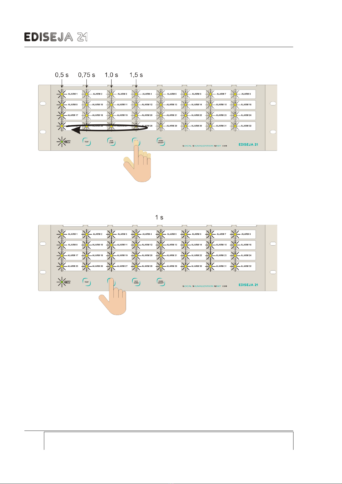
Press and hold button »ACK HORN« for approximately 3 s.
All lamps goes ON for 1 s.
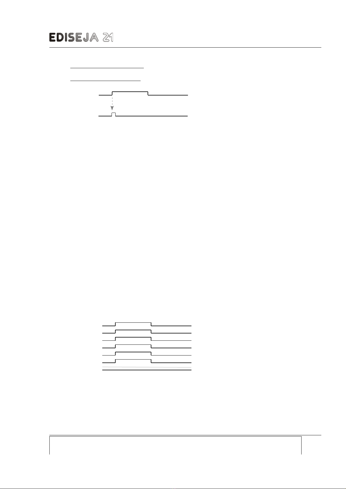
De ice is now in set lamp flashing speed mode. All lamps are flashing except first, second,
third or fourth row column. Which column is ON depends on current setting. Column which is
ON marks the speed of lamp is flashing:
first column ON - flashing on 0,5 s
second column ON - flashing on 0,75 s
third column ON - flashing on 1 s
fourth column ON - flashing on 1,5 s.
Device: Document: Code: Date: Page:
LSU 110 / 32 User manual LS3MUE01 15.08.2020 9
LSU 110 / 32 - Local Signalization Unit User manual
Change the speed of lamp flashing with button »ACK HORN«.
Lamp flashing speed setting is confirmed with button »ACK HORN«. All lamps goes ON for
1 s. De ice is now in set lamp logic mode.
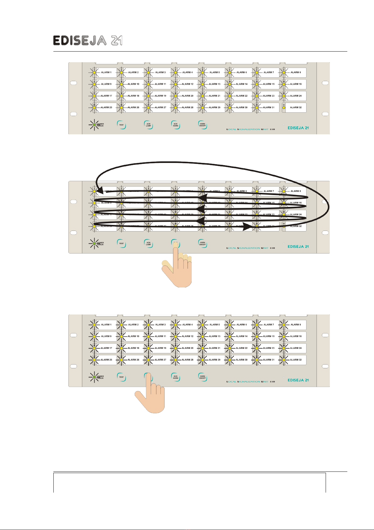
Lamp logic setting:
lamp flashing means, that when dependent input will go acti e, lamp will flash until »ACK
LAMP« is pressed („OPERATION„ (»lamp – B«))
lamp ON means, that lamp will follow the input state; acti e inpute lamp ON, non acti e
input lamp OFF (chapter „OPERATION„ (»lamp – A«))
lamp OFF means lamp we are currently set (lowest right).
Page: Device: Document: Code: Date:
10 LSU 110 / 32 User manual LS3MUE01 15.08.2020
LSU 110 / 32 - Local Signalization Unit User manual
Mo e to lamps by pressing button »ACK HORN«.
Single lamp logic setting is changed with button »ACK LAMP«.
When all lamps logic are set press and hold button »ACK HORN« for approximately 3 s.
Device: Document: Code: Date: Page:
LSU 110 / 32 User manual LS3MUE01 15.08.2020 11

LSU 110 / 32 - Local Signalization Unit User manual
All lamps goes ON for 1 s. De ice is now in set rising edge mode.
Rising edge setting:
lamp flashing means lamp we are currently set (lowest right)
lamp ON means that lamp will be energized by high potential
lamp OFF means that lamp will be energized by low potential.
Page: Device: Document: Code: Date:
12 LSU 110 / 32 User manual LS3MUE01 15.08.2020

LSU 110 / 32 - Local Signalization Unit User manual
Mo e to lamps by pressing button »ACK HORN«.
All lamps goes ON for 1 s. De ice is now in set time delay mode.
First left lamp is ON and it marks the lamp (binary inputs) to be set. Last righ lamp is
flashing. Flashing lamp marks the setting position.
Set time delay for each lamp according to the pictures:
Device: Document: Code: Date: Page:
LSU 110 / 32 User manual LS3MUE01 15.08.2020 13


LSU 110 / 32 - Local Signalization Unit User manual
Select / deselect time setting by pressing button »ACK LAMP«. If lamp is ON, selected time
delay is acti e. If lamp is OFF, selected time delay is not acti e.
Mo e between lamps by pressing button »TEST«.
Device: Document: Code: Date: Page:
LSU 110 / 32 User manual LS3MUE01 15.08.2020 15


LSU 110 / 32 - Local Signalization Unit User manual
First row marks the de ice address (on the picture de ice adress = 3). Second row marks
station address. Last righ lamp in second row is flashing. Flashing lamp marks the setting
position.
Mo e between lamps by pressing button »TEST«.
Select / deselect address bit setting by pressing button »ACK LAMP«. If lamp is ON, selected
bit is acti e. If lamp is OFF, selected bit is not acti e.
When IEC 60870-5-103 de ice address and IEC 60870-5-103 station address are set press
and hold button »ACK HORN« for approximately 3 s.
All lamps goes ON for 1 s.
De ice goes into reset.
After reset de ice is in operating mode.
Device: Document: Code: Date: Page:
LSU 110 / 32 User manual LS3MUE01 15.08.2020 17
LSU 110 / 32 - Local Signalization Unit User manual
5 IEC 60870-5-103 PROTOCOL
5.1 INFORMATION TA LE
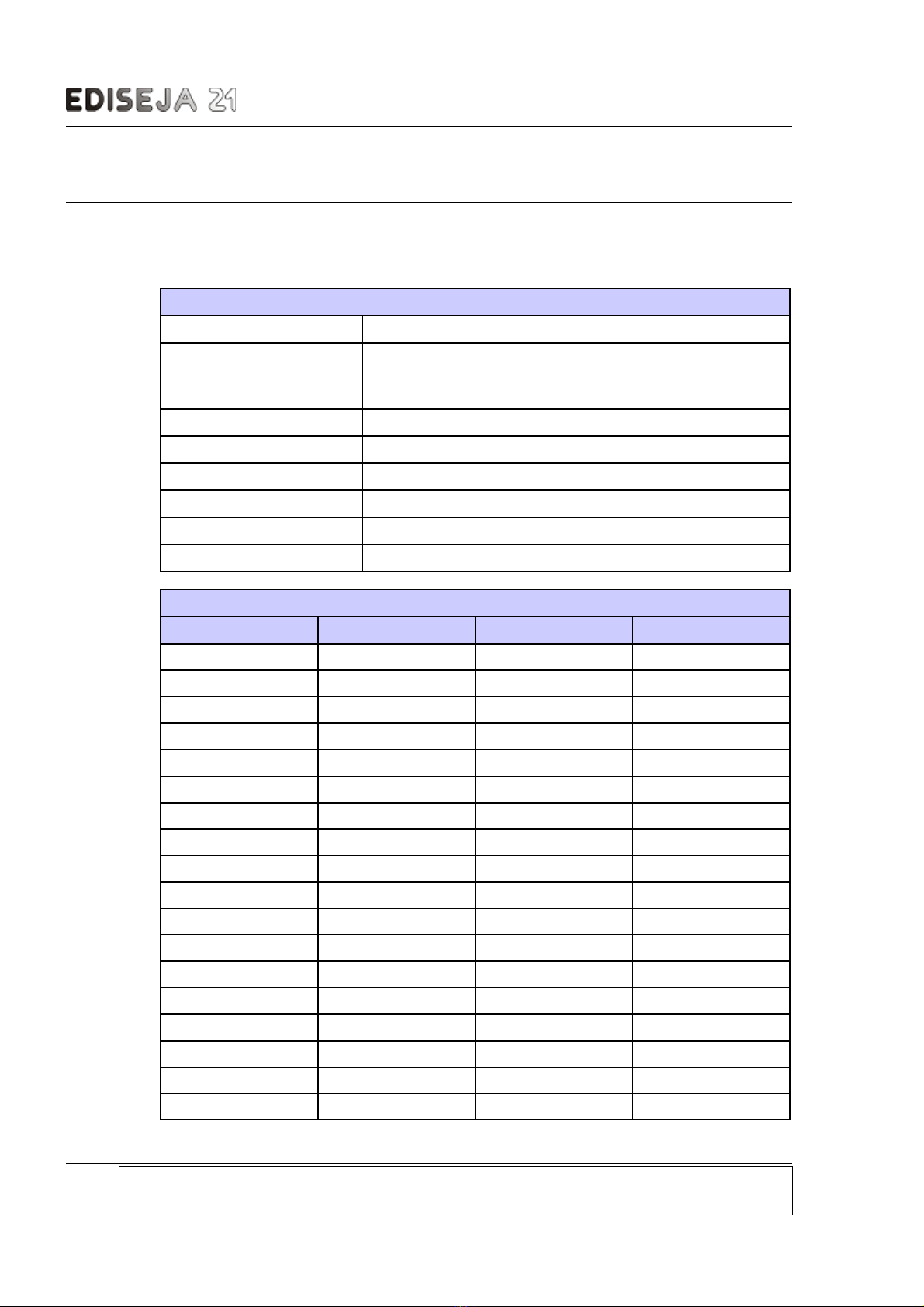
Communication
Protocol IEC 60870-5-103 (sla e)
Supported responds
link reset, class I, class II, general interrogation, time
synhronization (broadcast & single de ice), general
command
Device address 1 - 255
Station address 1 - 255
aud rate 19200 (fixed)
Number of data bits 8 (fixed)
Parity e en (fixed)
Number of stop bits 1 (fixed)
Device IEC 60870-5-103 information table
Signal description Function Information number GI respond number
digital input 1 240 160 1
digital input 2 240 161 2
digital input 3 240 162 3
digital input 4 240 163 4
digital input 5 240 164 5
digital input 6 240 165 6
digital input 7 240 166 7
digital input 8 240 167 8
digital input 9 240 168 9
digital input 10 240 169 10
digital input 11 240 170 11
digital input 12 240 171 12
digital input 13 240 172 13
digital input 14 240 173 14
digital input 15 240 174 15
digital input 16 240 175 16
digital input 17 240 176 17
digital input 18 240 177 18
Page: Device: Document: Code: Date:
18 LSU 110 / 32 User manual LS3MUE01 15.08.2020

LSU 110 / 32 - Local Signalization Unit User manual
Device IEC 60870-5-103 information table
digital input 19 240 178 19
digital input 20 240 179 20
digital input 21 240 180 21
digital input 22 240 181 22
digital input 23 240 182 23
digital input 24 240 183 24
digital input 25 240 184 25
digital input 26 240 185 26
digital input 27 240 186 27
digital input 28 240 187 28
digital input 29 240 188 29
digital input 30 240 189 30
digital input 31 240 190 31
digital input 32 240 191 32
digital output 1 200 160 NO GI
digital output 2 200 161 NO GI
digital output 3 200 162 NO GI
digital output 4 200 164 NO GI
digital output 5 200 165 NO GI
digital output 6 200 (*) 166 (*) NO GI
(*) Valid for LSU 110 / 32.x.x.x.S types only! For LSU 110 / 32.x.x.x.N de ices, this
output indicates de ice "ready" status!
5.2 EXAMPLES OF REQUEST RESPOND SEQUENCES
(De ice address: 1)
Telegrams legend:
-master request
-sla e respond
"Link reset"
10 40 01 41 16
10 00 01 01 16
"Time synch - broadcast"
68 0F 0F 68 44 FF 06 81 08 FF FF 00 9C 01 33 91 45 05 14 8F 16
"GI start"
68 09 09 68 53 01 07 81 09 01 FF 00 00 E5 16
10 00 01 01 16
10 7B 01 7C 16
Device: Document: Code: Date: Page:
LSU 110 / 32 User manual LS3MUE01 15.08.2020 19

LSU 110 / 32 - Local Signalization Unit User manual
68 0E 0E 68 08 01 01 81 09 01 F0 A0 01 E5 01 33 11 00 50 16
10 5A 01 5B 16
68 0E 0E 68 08 01 01 81 09 01 F0 A1 01 72 05 33 11 00 E2 16
10 7A 01 7B 16
68 0E 0E 68 08 01 01 81 09 01 F0 A2 01 6C 09 33 11 00 E1 16
10 5B 01 5C 16
68 0E 0E 68 08 01 01 81 09 01 F0 A3 02 CF 09 33 11 00 46 16
"GI end"
10 7A 01 7B 16
68 09 09 68 08 01 08 81 0A 01 FF 00 00 9C 16
"Class 1 read"
10 5A 01 5B 16
10 09 01 0A 16
10 7B 01 7C 16
10 09 01 0A 16
10 5A 01 5B 16
10 09 01 0A 16
10 7A 01 7B 16
10 09 01 0A 16
10 5B 01 5C 16
10 09 01 0A 16
"DO2"
68 0A 0A 68 73 01 14 81 14 01 C8 A1 02 01 8A 16
10 00 01 01 16
"DO3"
68 0A 0A 68 73 01 14 81 14 01 C8 A2 02 02 8C 16
10 00 01 01 16
"DO4"
68 0A 0A 68 73 01 14 81 14 01 C8 A3 02 03 8E 16
10 00 01 01 16
Page: Device: Document: Code: Date:
20 LSU 110 / 32 User manual LS3MUE01 15.08.2020
Table of contents


