Beck com.tom RADIO 3.2 User guide

com.tom RADIO 3.2 – Start-up Guide
In widely distributed systems or in envi-
ronments without network infrastructure
wireless solutions are required for the
simplest telecontrol/remote maintenance
functions.
The communication mechanism of the
com.tom devices ensures problem-free
use in all wireless networks without the
need for special SIM cards.
Device may only be put into service and
operated by qualified personnel. The
device is designed for an installation on a
grounded 35 mm DIN rail in dry rooms.
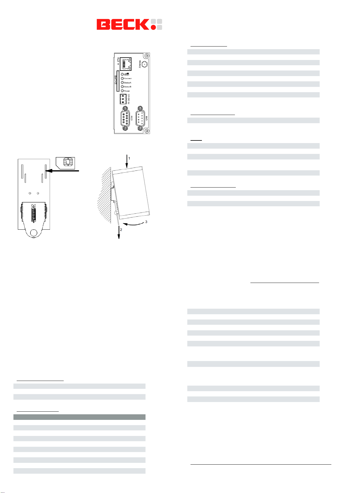
Insert the SIM card in the
device’s rear before the installation on the DIN rail. The device must
be switched off.
Never use the device in areas where the operation of wireless
equipment is prohibited. The location for the antenna must guaran-
tee the recommended radiological limits (be at least 20 cm from
persons and other antennas).When the antenna is installed out-
doors the lightning protection standard VDE V0185 must be com-
plied with. The EMC lightning protection zone concept must be
observed. The device must be switched off during work on the
antenna. It cannot be guaranteed, that there will not be any harmful
interference for other devices. In case of interferences install the
device or the antenna in another location.
After the installation the housing of the device is connected with
functional earth.
The power supply must be a grounded circuit (PELV).
The power supply must be a limited power source according to
EN60950-1 cap. 2.5 or the device must be provided with an anti-
surge fuse of 2 A.
Pin Assignment
Power Supply
FE Functional earth
GND Ground
VCC 24 VDC
Serial Interface
RS232 RS485 RS422
Pin 1 NC A(-/Y) A(TxD)
Pin 2 RxD NC NC
Pin 3 TxD NC NC
Pin 4 NC NC A'(RxD)
Pin 5 GND GND GND
Pin 6 NC B(+/Z) B(TxD)
Pin 7 RTS NC NC
Pin 8 CTS NC NC
Pin 9 NC NC B'(RxD)
Housing Connected to functional earth
CAN Interface
Pin 1 NC
Pin 2 CAN_L
Pin 3 CAN_GND
Pin 4 NC
Pin 5 CAN_SHLD (optional)
Pin 6 CAN_GND
Pin 7 CAN_H
Pin 8 NC
Pin 9 NC
Housing Connected to functional earth
Ethernet Interface
Green LED Link indication
Yellow LED Activity indication
LEDs
Modem Modem is initialized
GSM/GPRS GPRS Internet Connection successful
Status A Communication with Portal successful
Status B Program loaded (on) / executed (flashing) /
stopped (off)
Power Device is powered
Other Interfaces
SD card interface MMC/SD card
Antenna connector SMA connector
SIM card interface SIM card
Getting Started
Wire the com.tom device according to the technical data.
Afterwards get the Getting Started documentation com.tom-
CODESYS at www.beck-ipc.com/gettingstarted and follow the
steps described there to put your com.tom device into opera-
tion.
General Data
Size (W x L x H) 46 x 103 x 63 mm
Operating temperature 0 bis 55 °C
Electrical shock Class III
Protection rating IP20
EMC emission IEC 61000-6-4
EMC immunity IEC 61000-6-2
Compliance CE, RoHS
Electrical Data
Supply voltage 24 VDC (15 %)
Active current 0.120 mA
Scope of supply
1 Piece com.tom Radio 3.2
1 Piece Start-up guide
1 Piece Connector 3-pin
1 Piece Label MAC-ID
Copyright © 2013 Beck IPC GmbH
www.beck-ipc.com
com.tom RADIO 3.2 – Inbetriebnahmeanleitung
Bei weit verteilten Systemen oder Umge-
bungen ohne Netzwerkinfrastruktur sind
Mobilfunklösungen der einfachste Weg
Fernwirken/Fernwarten zu realisieren.
Der Kommunikationsmechanismus der
com.tom-Geräte sichert eine problemlose
Nutzung in allen Mobilfunknetzen ohne
besondere SIM-Karten mit dem com.tom
WEB-Portal.
Montage und Inbetriebnahme darf nur
durch qualifiziertes Personal erfolgen.
Das Gerät ist für eine Montage auf geerde-
ten 35-mm-Hutschienen in trockenen
Räumen vorgesehen.
Die SIM-Karte ist vor dem Aufschnappen auf die Hutschiene auf der
Rückseite des Gerätes im ausgeschalteten Zustand einzusetzen.
Das Gerät darf nicht in Bereichen, in denen der Betrieb von Funk-
anlagen untersagt ist, betrieben werden. Bei der Auswahl des
Montageortes der Antenne muss die Einhaltung der Strahlungs-
grenzwerte gewährleistet sein (Mindestabstand von 20 cm zu Per-
sonen und anderen Antennen). Bei der Installation der Antenne im
Freien ist die Einhaltung der Blitzschutznorm VDE V 0185 vorge-
schrieben. Das Blitzschutzzonenkonzept darf durch die Antenne
und ihre Zuleitung nicht aufgehoben werden. Bei Arbeiten an der
Antenne muss das Gerät ausgeschaltet sein. Es kann nicht garan-
tiert werden, dass das Gerät keine störenden Interferenzen mit
anderen Geräten bewirkt. Falls es Interferenzen gibt, ist ein anderer
Montageort für das Gerät bzw. die Antenne zu suchen.
Im montierten Zustand ist das Gehäuse des Gerätes mit Betriebs-
erde verbunden. Die Stromversorgung ist als PELV Stromkreis
(Verbindung zwischen Masse und Betriebserde) auszuführen. Die
Stromversorgung muss eine Stromquelle mit begrenzter Energie
nach EN60950-1 Kap. 2.5 sein oder das Gerät ist mit einer Siche-
rung 2 A träge abzusichern.
Anschlussbelegung
Spannungsversorgung
FE Betriebserde
GND Masse
VCC 24 VDC
Serielle Schnittstelle
RS232 RS485 RS422
Pin 1 NC A(-/Y) A(TxD)
Pin 2 RxD NC NC
Pin 3 TxD NC NC
Pin 4 NC NC A'(RxD)
Pin 5 GND GND GND
Pin 6 NC B(+/Z) B(TxD)
Pin 7 RTS NC NC
Pin 8 CTS NC NC
Pin 9 NC NC B'(RxD)
Gehäuse mit Betriebserde verbunden
CAN-Schnittstelle
Pin 1 NC
Pin 2 CAN_L
Pin 3 CAN_GND
Pin 4 NC
Pin 5 CAN_SHLD (optional)
Pin 6 CAN_GND
Pin 7 CAN_H
Pin 8 NC
Pin 9 NC
Gehäuse mit Betriebserde verbunden
Ethernet-Schnittstelle
grüne LED Link-Anzeige
gelbe LED Aktivitätsanzeige
LEDs
Modem Modem ist initialisiert
GSM/GPRS GPRS-Internetverbindung hergestellt
Status A Kommunikation mit Portal erfolgreich
Status B Programm geladen (ein)
/ wird ausgeführt (blinkend) / gestoppt (aus)
Power Versorgungsspannung vorhanden
Weitere Schnittstellen
SD-Kartenschacht MMC/SD-Karten
Antennenschnittstelle SMA-Buchse
SIM-Kartenschacht SIM-Karten
Inbetriebnahme
Schließen Sie das com.tom-Gerät entsprechend den Vorga-
ben an. Laden Sie die Getting-Started-Dokumentation
com.tom-CODESYS von www.beck-ipc.com/gettingstarted
herunter und folgen Sie den dort beschriebenen Schritten, um
Ihr com.tom-Gerät in Betrieb zu nehmen.
Allgemeine Daten
Maße (B x L x H) 46 x 103 x 63 mm
Betriebstemperatur 0 bis 55 °C
Schutzklasse Klasse III
Schutzart IP20
Störaussendung IEC 61000-6-4
Störfestigkeit IEC 61000-6-2
Prüfzeichen CE, RoHS
Elektrische Daten
Versorgungsspannung 24 VDC (15 %)
Betriebsstrom < 120 mA
Lieferumfang
1 Stück com.tom Radio 3.2
1 Stück Inbetriebnahmeanleitung
1 Stück Steckverbinder 3-polig
1 Stück Etikett MAC-Adresse
TN 748347
Version 1.1
Table of contents
Languages:


