Edison IRT537 User manual

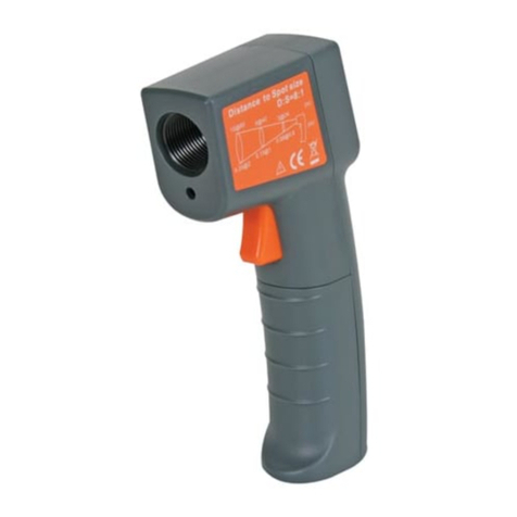
Infrared Thermometer
OPERATING MANUAL
FFuunnccttiioonnss
•UUsseeffoorraauuttoommoottiivveeddiiaaggnnoossttiiccss::AAiirrccoonnddiittiioonniinngg,,hheeaatteerrss,,rraaddiiaattoorrss,,tthheerrmmoossttaattss,,
mmiissffiirriinnggccyylliinnddeerrss,,ccaattaallyyttiiccccoonnvveerrtteerrss,,bbrraakkeess&&ttyyrreess..
•AAvveerraaggee,,mmaaxxiimmuumm,,mmiinniimmuumm&&mmaaxx--mmiinnmmooddeesseelleeccttiioonn..
•TTeemmppeerraattuurreerraannggee::--2200°°CCttoo553377°°CC..
•OOppttiioonnaall°°CC//°°FFddiissppllaayysseelleeccttiioonn..
•DDiissttaannccee::SSppoottssiizzeerraattiioo::1122::11..
•LLaasseerrppooiinntteerrbbeeaamm..
•EEmmiissssiivviittyy::00..9955..
•CClleeaarrddiissppllaayywwiitthhLLCCDD
bbaacckklliigghhttffuunnccttiioonn..
•AAuuttooppoowweerr‘‘OOFFFF’’aanndd
lloowwppoowweerriinnddiiccaattoorr..
ORDER CODE: EDI-312-4000K
MODEL IRT537
CLASS 2
LASER
EDI-312-4000K_Instructions.qxd 28/07/2010 15:34 Page 1

2
CONTENT
1. GENERAL INSTRUCTIONS ......................................................................................2
2. DESCRIPTION ..........................................................................................................3
3. TECHNICAL SPECIFICATIONS ..................................................................................4
4. OPERATING INSTRUCTION ......................................................................................4
5. MAINTENANCE ........................................................................................................7
1.
GENERAL INSTRUCTIONS
The Edison IRT537 Infrared Thermometer is manufactured to a high standard
and is easy to use. Simply aim at the target object, pull the trigger and read the
current surface temperature from the LCD display. If necessary the laser can be
activated via the laser button for a more accurate targeting.
To get the best service from this instrument, read carefully this operating manual
and respect the detailed safety precautions.
2.
SAFETY INFORMATION
• This instrument should only be used by qualified personnel and should be kept
out of the reach of children.
• Great care should be taken when using the thermometer, not to point the laser
in the direction of any other person, animal or moving object. The user
should also be aware of the danger posed by indirect exposure via reflective
surfaces.
DDiirreecctteeyyeeccoonnttaaccttwwiitthhtthheellaasseerrbbeeaammccoouullddrreessuullttiinnppeerrmmaanneenntt
ddaammaaggee..
•DDOONNOOTTuse the thermometer for any other purpose, other than that for which
it is intended.
•DDOONNOOTTallow the thermometer to be exposed to wet or damp conditions, to be
subjected to rapid changes in ambient temperatures, or to be exposed to
electro-magnetic fields, static electricity or high temperatures.
•DDOONNOOTTclean the thermometer using any solvents or abrasives.
• This instrument complies with European CE safety standards, and is also
compatible with the following: EN61326.
EDI-312-4000K_Instructions.qxd 28/07/2010 15:34 Page 2

3
Infrared Thermometer
3.
DESCRIPTION
1. Laser on indicator
2. Measurement indicator
3. Emissivity indicator
4. °C temperature unit
5. °F temperature unit
6. Average temperature
7. Average value indicator
8. MAX/MIN indicator
9. Battery low indicator
10. Current temperature
11. Data hold indicator
11
12
13
14
15
16
17
18
19 20
1
11 4
5
10
9
8 6
2 3
7
11. Collimator
12. Laser emission aperture
13. Temperature detect aperture
14. Trigger
15. Battery cover
16. LCD display
17. Laser button
18. °C/°F button
19. Mode button
20. Backlight button
Fig 1.
Fig 2.
EDI-312-4000K_Instructions.qxd 28/07/2010 15:34 Page 3

4.
TECHNICAL SPECIFICATIONS
•TTeemmppeerraattuurreerraannggee::-2O°C to 537°C / -4°F to 999°F.
•DDiissttaannccee::SSppoottssaazzeerraattiioo::12 : 1.
•AAccccuurraaccyy::-20°C to 50°C ± 2.5°C.
+5l°C to 537°C ± (reading x 1% + 1°C).
•AAuuttoommaattiiccttuurrnnooffff::Hold for 10 seconds.
•OOppeerraattiinnggccoonnddiittiioonnss::0 to 40°C, 10 to 90%RH.
•SSttoorraaggeeccoonnddiittiioonnss::-10°C to 60°C, ≤75%RH.
•EEmmiissssiivviittyy::0.95.
•RReessppoonnsseettiimmee::0.5 second.
•SSppeeccttrraallrreessppoonnssee::8- to 14µm.
•LLaasseerrppoowweerr::<1mw.
•PPoowweerrssoouurrccee::9V battery (6F22 equivalent).
•SSiizzee((HHxxWWxxDD))::19Omm x 56mm x 162mm.
•WWeeiigghhtt::Approx. 258g (including battery).
5.
OPERATING INSTRUCTION
5.1 How Does The Infrared Thermometer Work?
The thermometer detects infrared energy, which is emitted by all objects.
This infrared energy is captured by the thermometer and processed through a
sensor. The sensor generates a measurable voltage output which is in proportion
to the target temperature. The output is processed and displayed on the LCD.
5.2 Instructions For Use
Pull and hold trigger (laser pointer is off by default) to
activate the thermometer. Point the thermometer
toward the target object and depress the trigger. On
releasing the trigger the reading will display for 10
seconds before the auto off function is activated. While the trigger is depressed,
alternative formats and features can be accessed via the keypad.
Pressing the laser button (see Fig. 3) activates /deactivates the laser facility.
The temperature format can be changed from Fahrenheit (default) to Celsius by
means of the °°CC//°°FFbutton (see Fig. 3). Pressing this button allows the user to
work between the two temperature scales. A backlight feature is also
available (see Fig. 3), allowing the user to work in reduced light conditions. The
MMOODDEEkey will let you check temperature variations between ‘Average’ (default),
‘Maximum’, ‘Minimum’ or ‘Maximum/Minimum’ reading. Just press the MMOODDEE
key consecutively to achieve the desired setting.
4
Fig 3.
EDI-312-4000K_Instructions.qxd 28/07/2010 15:34 Page 4

5
Infrared Thermometer
5.3 Emissivity
Depending on the nature of the material which is to be scanned, different levels
of energy will be encountered (emissivity). However, most organic and painted or
oxidised surfaces have an emissivity of 0.95. To overcome any problems with
polished or mirrored surfaces, they should be covered in masking tape or matt
black paint before scanning. Allow time for the tape or paint to attain the same
temperature as the target object before scanning.
5.4 Hot Spots
In order to locate a hot spot, aim the thermometer away from the target, before
scanning across the target in an up and down motion, keeping the trigger
depressed until the hot spot is located (See Fig. 4).
5.5 D:S Ratio (Field of View)
The D : S Ratio (Distance to Spot size) or Field Of View is 12 : 1 (See Fig. 5). This
ratio indicates that when the target object is 300mm (12") away from the
thermometer, then the target object should be at least 25mm (1"). In general, it is
good practice to ensure
that the target is larger
than the spot size. The
smaller the spot size,
the closer the
thermometer should be
to the target object. For
increased accuracy, the
target should be twice
the size of the spot size.
Fig 5.
Target Area
Keep trigger depressed
while scanning in an up
and down motion.
Fig 4.
EDI-312-4000K_Instructions.qxd 28/07/2010 15:34 Page 5

6
5.6 Vehicle Diagnostics
CCaarreesshhoouullddbbeettaakkeennwwhheennwwoorrkkiinnggoonnvveehhiicclleess,,aasstthheeuusseerrmmaayyffiinndd
tthheemmsseellvveesswwoorrkkiinnggiinncclloosseepprrooxxiimmiittyyttoovveerryyhhoottccoommppoonneennttss,,ssuucchh
aassrraaddiiaattoorrssaannddeexxhhaauussttmmaanniiffoollddss..
AAiirrCCoonnddiittiioonniinngg::With the air conditioning set to maximum cooling, the output air
temperature should be in excess of 15°C colder than the ambient temperature
outside the vehicle. To avoid the instrument being affected by thermal shock, the
thermometer should be focused on the air duct rather than directly into the cold
air stream. Temperature differentials of less than 15°C indicate that the air
conditioning system may need to be checked.
HHeeaatteerr::To test the heater it should be turned on, while the air conditioning
should be off. With the engine running at the usual operating temperature, the
user should take a reading from the heater inlet and outlet hoses. It would be
expected that the outlet would be approximately 10°C cooler than the inlet hose.
Any significant difference in the two figures indicates restricted through flow,
which should be investigated.
RRaaddiiaattoorr::With the engine running at the normal operating temperature, the user
should check the temperature drop on the inlet and outlet. The drop in
temperature should be fairly even. Scan the radiator surface (see Fig. 4) for any
cold spots, which are symptomatic of a blockage.
TThheerrmmoossttaatt::To check that a vehicles thermostat is performing as expected, it is
necessary to monitor the temperature of the hose adjacent to the thermostat
housing. If the thermostat is working properly, it will open as the vehicle reaches
its normal operating temperature (85-105°C). This is apparent, as there is a
temperature surge in the hose. If the hose temperature increases gradually, but
never reaches operating temperature, the thermostat is faulty or is missing. In
the event of no rise in temperature, this indicates that the thermostat is stuck in
the closed position, or other parts, such as the pump have failed.
Fluctuating temperature readings are indicative of a failed spring in the
thermostat, or air in the system.
CCyylliinnddeerrMMiissffiirriinngg::Injector and manifold gasket problems can be detected by
taking temperature readings from the separate branches of the exhaust
manifold. If one of the branches is much cooler than the others, then a misfiring
cylinder is indicated. In this case, the difference in temperature will be more
pronounced before the engine is at normal operating temperature. If an exhaust
branch is hotter than others, it is likely that a weak mixture is reaching that
cylinder.
EDI-312-4000K_Instructions.qxd 28/07/2010 15:34 Page 6

7
Infrared Thermometer
CCaattaallyyttiiccCCoonnvveerrtteerr::Problems with catalytic converters can be diagnosed by
running the engine until the normal operating temperature is achieved, and the
engine is running at 1000rpm. Under these conditions, the inlet should be >55°C
(2-way) or >20°C (3-way). When the outlet temperature is lower than the inlet
temperature, the converter must be blocked and must therefore be replaced. If
the temperatures are the same at the inlet and outlet then the converter is worn
out and must be replaced or the converter material has degraded. Always
investigate the cause of failure before replacement.
BBrraakkeess::To check on the comparative braking capability on a vehicle, it is
necessary to bring the brakes up to operating temperature by braking 5-6 times
from 30mph to standing, before measuring the temperature of the disk/drum
immediately afterwards. Brakes on the same axle should not differ by >3°C. The
front brakes should be around 30°C hotter than the rear brakes. If one brake on
an axle does not meet these criteria then it is likely that the brake showing the
lower temperature is faulty.
TTyyrreess::After driving the vehicle for a few miles, readings can be taken from the
outer, centre and inner tread. A higher temperature at the inner and outer
sections of the tread indicates that the tyre is under-inflated. If the centre of the
tread is hotter than the other two points then the tyre is over inflated. Any
discrepancies may be attributed to inflation or suspension faults.
6.
MAINTENANCE
6.1 Charging The Battery
When the battery low warning symbol
is showing, it indicates that the battery is
almost exhausted and must be replaced.
To replace the battery, pinch together the
open symbols on each side of the handle,
and pull the hinged battery access
section forward. Remove the old battery
and replace with a 9 Volt battery (6F22).
Please dispose of your old battery in
a responsible manner.
Order code for replacement battery:
EDI-904-3000K.
Fig 6.
EDI-312-4000K_Instructions.qxd 28/07/2010 15:34 Page 7

Edison Products are continuously being developed and improved.
All details and illustrations are for guidance and may be subject to change.
89/336/EEC amended by 93/68/EEC
DECLARATION OF
CONFORMITY
We hereby certify that the EDISON IRT537 Infrared Thermometer
complies with:
EN61326:1997 / +A1:1998/+A2:2001/+A3:2003
Official Agent
The Kennedy Group Ltd
EDISON
The Power Factory, PO Box 14, Wigston, Leicester, England.
Signed:
Name: Martin Cooke
Position: Director, The Kennedy Group Ltd
Date: June 2010
Always dispose of unwanted tools, accessories and packaging materials in an
environmentally friendly manner.
For EU and EEA countries only.
In observance of European Directive 2002/96/EC on Waste Electrical and
Electronic Equipment (WEEE) and its implementation in accordance with national
law, electrical goods that have reached the end of their life must be collected separately
and returned to an environmentally compatible recycling facility.
Do not dispose of electrical goods with domestic waste materials as inappropriate
disposal may cause potential hazards to the environment and human health.
For further information, please contact your local authority or the retailer from whom you
purchased the product.
EDI-312-4000K_Instructions.qxd 28/07/2010 15:34 Page 8
Table of contents
Other Edison Thermometer manuals


