EDLUND 270 User manual

SERVICE MANUAL- M131 REVA
MODEL 270 ELECTRIC CAN OPENER

M131
2
Repair and Service Guidelines
When a Model 270 electric can opener is returned to the factory for warranty repair, repair or for any
other service issues, the following procedure will be used:
1. Read the Quality Improvement Report that accompanies the product to determine what problems
or complaints that the customer has listed.
2. Perform a ground continuity test and a dielectric withstand test according to the Final Inspection
Procedure EC1062.
A. If the unit passes both tests, proceed to step #3.
B. If the unit fails the ground continuity test, proceed to step #7.
C. If the unit passes the ground continuity test but fails the dielectric withstand test, proceed to
step #8.
3. If the unit passes both the ground continuity and the dielectric withstand test, it is safe to operate.
Plug the cord set into a receptacle with the same voltage as listed on the rating label and check to
be sure the motor runs when the actuating lever is actuated.
4. A. If the customer has not listed any problems or complaints, proceed to step #6.
B. If the customer has listed any problems or complaints in the Quality Improvement Report, check
to see if these complaints can be duplicated.
5. If the can opener functions as the customer has described, proceed to the
Troubleshooting Guide to find the cause or causes of the problem and correct according to the
correction procedure listed in the Trouble Shooting Guide and then perform the Final Inspection
Procedure EC1062.
6. If the can opener does not function as the customer has described or if the customer has not listed
any problems or has not fully described the problem, open a few cans to determine just how the
can opener is functioning. Check the front to back clearance between the back of the knife and the
front of the gear. When the actuating lever is in the down position to make sure it is 0.017 – 0.022
wide. Check the up and down clearance between the top of the drive gear and the bottom of the
knife holder with the knife removed and the actuating lever in the down position to be sure it is
between .102 - .107 inch. Check the on position of the motor to be sure the motor comes on just
as the knife starts down over the top of the drive gear teeth and that the motor starts before the
knife pierces the can.
If the can opener is not functioning properly, proceed to the Trouble Shooting Guide and find the
cause or causes of this problem. Correct the problem using the correction procedure listed and
perform the Final Inspection Procedure EC1062.
7. If the unit has failed the ground continuity test proceed to the Trouble Shooting Guide, find the
cause of the problem and correct according to the correction procedure. After the problem has
been corrected, proceed to step #2 to perform the ground continuity and the dielectric withstand
test to make sure that the unit is safe to operate before doing any repair.
8. If the can opener passes the ground continuity test, but fails the dielectric withstand test, consult
the Trouble Shooting Guide and correct the problem using the correction procedure listed.
9. If the actuating lever and cam assembly are removed for any reason, remove the
frame assembly and check the motor endplay and the length of the motor brushes. If the endplay
exceeds 0.035 inches, shim the motor to reduce the end-
play to 0.030 inches maximum. Replace the brushes and brush springs as needed.

M131
3
Model 270 Can Opener Assembly Procedures
The Model 270 and Model 270C can openers will be assembled according to the following procedure.
I. Model 270 & Model 270C Gear Plate Assembly (A272/A285 & A276)
1. Assemble the front and rear gear plate assemblies (A277) & (A276) by pressing the flanged bushing and straight bushing into
the respective bushing holes. Press a straight bushing (B169) into each end of the vertical holes in the rod mount (M075) and
attach the rod mount to the front gear plate (P184) using four screws (S321).
2. Assemble the gear latch spring (S308) and gear latch (A284), with notched cutout down, onto the front of the rod mount
(M075) and secure with two shoulder screws (S309) and Loctite No. 242. Be sure that the Loctite doesn't prevent up and down
motion of the gear latch.
3. Press the rod mount actuator (A059) into the central hole in the bottom of the rod mount and align holes. Secure with spring
pin (P029).
A272
A276

M131
4
Model 270 & Model 270C Motor and Gear \box Assemblies (A272/A285)
1. Install the thrust washer (W093) and the output gear assembly (A278) into the front gear plate
(A277). Install the second gear and pinion (A573) and the first gear and pinion (A572) into the
front gear assembly. Install the thrust washer (W039) and the output spring (S165) over the end
of the output shaft assembly. Install a gasket (G060) on the back of the gear plate assembly
(A277) and align holes. Install the gearbox housing (H068) over the gasket and insert gear
grease into the housing. Fill one-half full.
2. Install the motor with appropriate voltage onto the rear gear plate assembly (A276) by placing
the motor spacer (P182) over the two front studs of the motor and push the studs through the two
clearance holes of the gear plate and secure with two nuts (N019) and washers (W018).
3. Assemble the brush cap holder (H034L) over the two rear studs of the motor assembly and
secure with two nuts (N019) and washers (W018). Tighten the nuts while keeping the nuts on the
front of the gear plate assembly from turning. Make sure that the short motor leads with the clips
are pulled out of the brush cap holes of the brush cap holder and long leads are threaded through
hole in housing. Install brush (B117) and brush spring (S158) into brush holder. Insert the metal
clip of the short motor lead into the brush spring near its outer end. Install brush caps (C007)
over brush spring and metal clip and push down into the hole in the brush cap holder. Make sure
that the wire lead doesn't rub on the rotating armature.
4. Install a gearbox-housing gasket (G060) on the rear end of the gearbox housing (H068).
Place the rear gear plate and motor assembly over this gasket and secure with four screws
(S080) and Loctite No. 609. Warning: Do not use Loctite 242 for this application. Solvent in
Loctite causes cracking of plastic gear housing.

M131
5
II. Frame Assembly (A283/) (Fig. 8)
1. Assemble the lever assembly (A280) onto the bottom of the motor and gearbox assembly (A272/A285) using clevis pin
(P002) and cotter pin (P010).
2. Assembly one-rod retainer (R093) into the bottom of the frame assembly (A282) using two screws (S085) and washers
(W023) and Loctite 242.
3. Place motor and gear train (A272) into position in the frame and install the two rods (R092) down through the hole in the top
of the frame, through the bearings in the rod mount (M075) and into the holes in the bottom rod retainer. Place the other rod
retainer over the top ends of the rods, making sure that the oval slot on the top rod retainer aligns with the oval slot on the bottom
rod retainer. Secure with two screws (S085) and washers (W023) and Loctite No. 242. Do not tighten screws tight.
Slide motor and gearbox assembly up and down on the rods and make sure it slides easily with no restriction. Tighten the two
screws (S085).
4. Assemble the back of the lever assembly (A280) to the rear of the frame assembly using four screws (S049) and washers
(W021) to secure the two levers mounts (M076).
5. After the motor and gearbox are assembled into the frame it is necessary to make sure the distance from the front of the frame
(A282) to the front of the gear latch (A284) is less than 0.028 of an inch. If this distance is larger than 0.028 (0.7mm) inches,
then the latch may not lock the shield and drive gear in place. Measure distance using a depth micrometer or a Vernier caliper.
If distance is greater than 0.028 (0.7mm) inches, remove shoulder screws (S309) that secure gear latch and add shims (S418) or
(S417) under latch and insert shoulder screw through shims and secure using Loctite No. 242, Make sure that the latch is free to
move up and down after shoulder screws are tightened.

M131
6
IV. Assembly of Model 270 & 270C Frame Assembly into Housing Assembly (Fig. 1-Fig. 4)
1. With the top of the motor facing the rear of the housing, install the frame assembly into the bottom opening of the housing and
slide the frame assembly up against the rear of the housing faceplate. Secure the frame assembly in place from the bottom of the
housing using two screws (S049) and washer (W021) and Loctite No. 242. The socket head screws must be installed using a ball type
Allen wrench. Do not tighten screws tight.
2. Install the right shoulder screw (S316) and the left shoulder screw (S317) on to the two studs on the front of the housing using
Loctite No. 242. Turn the housing over and securely tighten the two screws (S042) that secure the bottom of the frame.
3. Install the shield assembly (A279) over the output shaft and check to make sure it latches by pressing on the shield where the metal
insert is located. If the shield will not latch remove the frame assembly and place shims behind the shoulder screws (S309) that retain
the gear latch. Replace the frame assembly and try latching the shield again. Repeat shimming procedure until the shield will lock in
place.
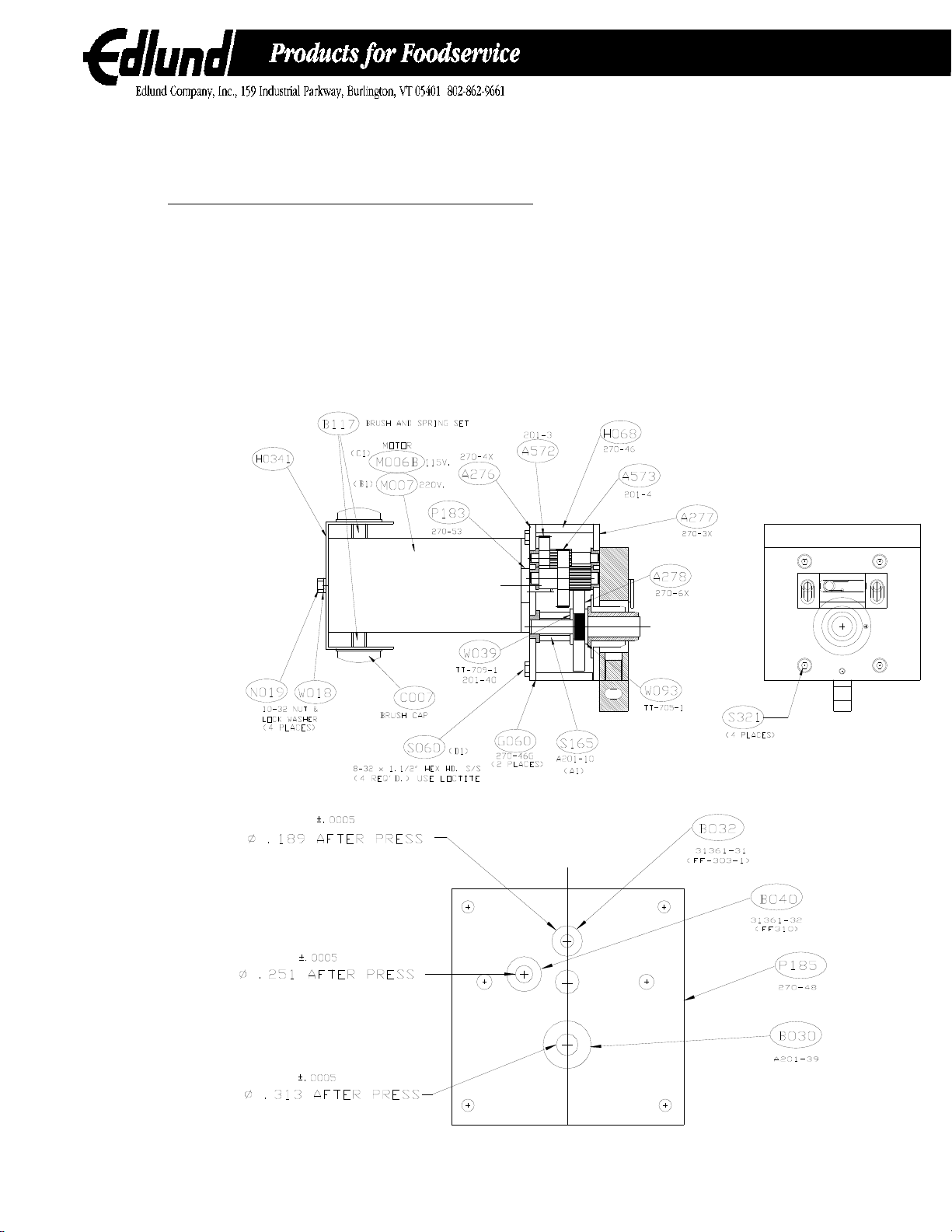
4. For Model 270, place a nut (N019) on screw (S050) and install into threaded hole in stop in throat of housing. This will be
adjusted later. (See Fig. 1)
5. Install the two lever arm mounts assemblies (A2812/A2812C) over the studs on the bottom inside of the housing
(A273/A273C/A2731). Secure with four nuts (N019) and lock washers (W018) but do not tighten at this time.
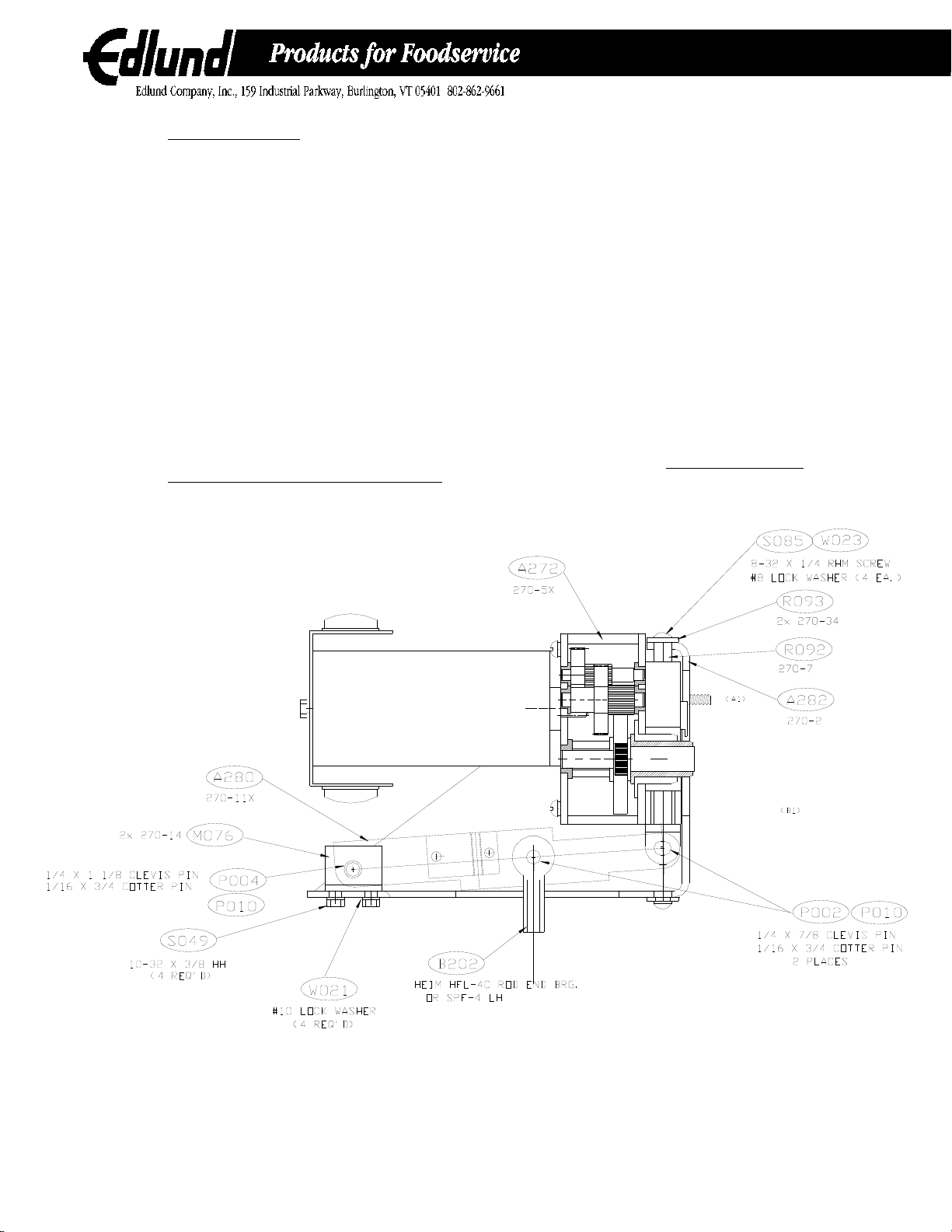
6. Attach the cam assembly consisting of height adjuster (A054), lock nut (N054), clevis (C243), cam (C192), shoulder screw (S299),
lock washer (W018) and lock nut (N056) to bottom of rod end (B202). Screw height adjuster (A054) into bottom of rod end by
turning screw counterclockwise (left hand thread) until space of ¼ inch exists between end of rod end (B202) and hex nut portion of
height adjuster.
7. Slide actuator lever (L065/L065C) through the hole in the housing, through the hole in the bearing mount, through the spacer
(S338) through the hole in the cam assembly and into the opposite bearing mount. With the lever in the raised position, align the hole
in the cam with the hole in the lever. Secure with a 3/16-inch diameter roll pin (P245). Tighten the four nuts (N019) that retain the
bearing mounts (A2812/A2812C).
8. Install the knife holder latch (L066) on right hand shoulder screw (S316) using the knife holder latch screw (S314). Install drive
gear adapter (A055) onto the output gear assembly (A278).
9. Place the shield assembly (A279) over the output shaft with the long side vertical and press in on the top until the shield is locked
in place. Slide the drive gear (G041) over the drive gear adapter and press in on the shield assembly until the gear is locked in place.
10. Install the knife holder (A288) onto the face of the housing by sliding the left hand slot of the knife holder over the left hand
shoulder screw (S317) and keep sliding to the left until the right hand slot of the knife holder engages the right hand shoulder screw
(S316). Rotate the knife holder down and lock in place with the knife holder latch (L066).
11. Set the height adjustment of the drive gear as follows:
A. Lower the actuating lever (L065/L065C) to the bottom and adjust the drive gear up or down by turning height adjuster (A054)
clockwise or counterclockwise until clearance between the bottom of the knife holder and the top of the drive gear is .100-.105 when
measured using gage and feeler gage. Lock height adjuster in place using the lock nut (N054).
12. For Model 270, adjust the lock screw until the cam assembly (A2815) doesn't rotate beyond the top of its arc. Lock the screw in
place using nut (N019).
For Model 270C, install the lock plate (P296) onto the bearing mount assembly (A2812C) using four screws (S049) and lock washers
(W018). Install screw (S048) and lock nut (N019) into the center hole of the lock plate as shown and adjust the screw until the cam
will not travel beyond the top of its arc. Secure the screw using the lock nut N019.
13. Install the switch actuator assembly (A049) and lock nut (N023) into the bottom of the lever assembly. Assemble the roller
switch assembly (A2814) on to the bottom of the frame using two screws (S085) and washers (W012) and (W023). Do not tighten the
two screws at this time.
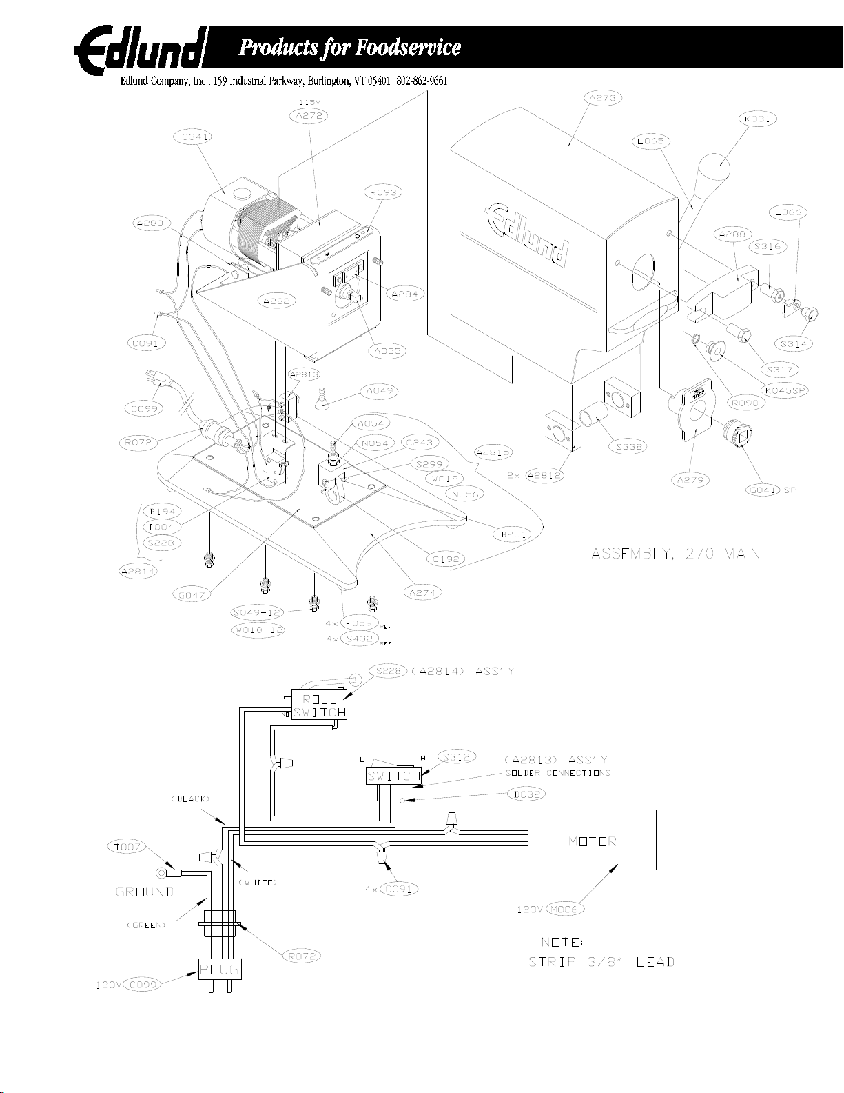
14. Install the rocker switch assembly (A2813) into the rectangular hole in the housing and install the appropriate cord set and strain
relief into the holes in the rear of the housing.
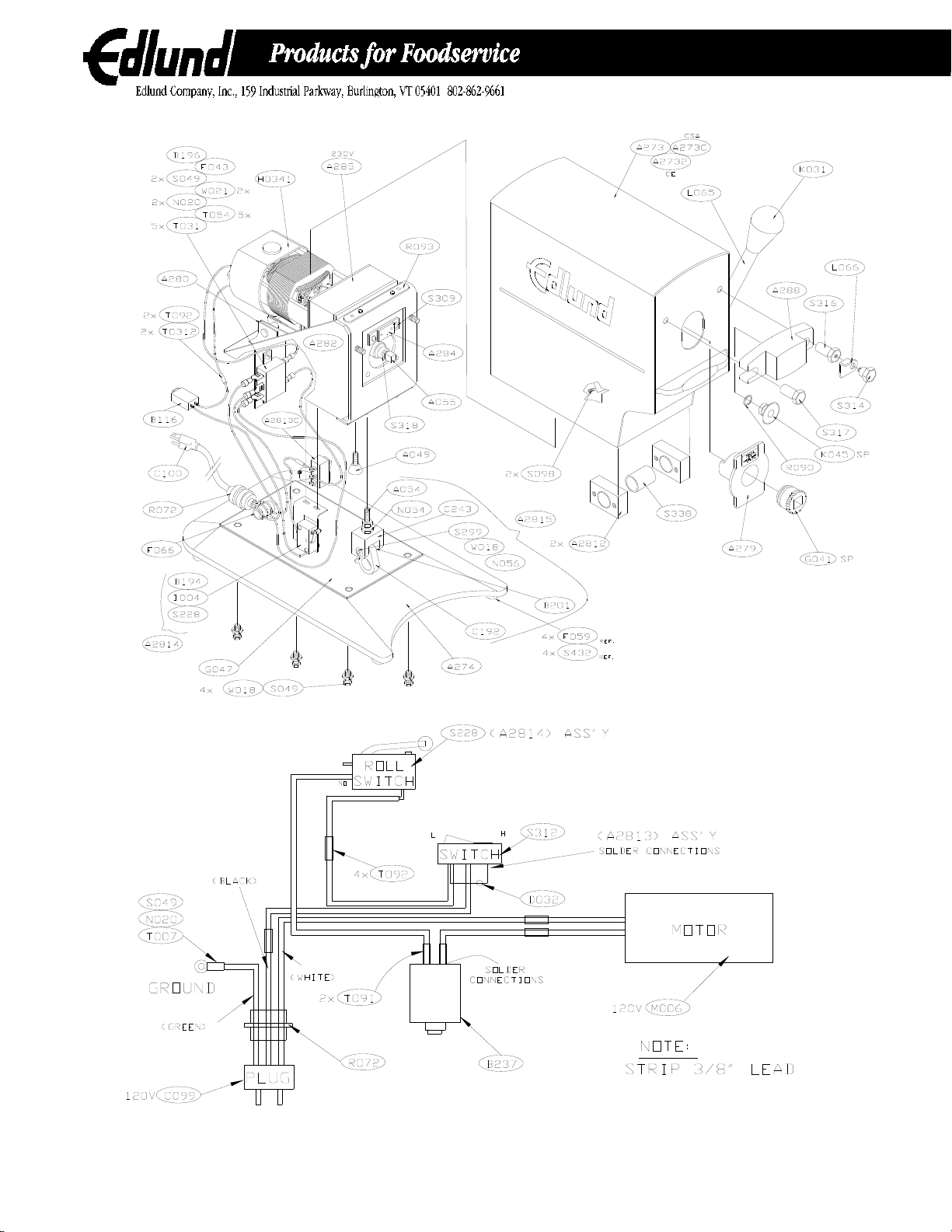
For 230 volt Model 270 or Model 270C, remove the two screws (S049) that secure rear of lever assembly to frame and attach filter
bracket (B196) and filter (F043) to bottom rear of frame and secure by inserting the two screws (S049) back in place.
15. Wire the can openers using the appropriate wiring diagram (Fig. 10 and 11). Bundle wires and tie up using wire tie.
16. Adjust the on position of the motor by pulling actuating lever down until the knife (K045) is even with the top of the gear (G041).
Turn switch actuator and slide the roller switch assembly (A2814) until the roller switch clicks on. Lock the switch actuator in place
using nut (N023) and tighten the two screws (S085) on the roller switch assembly. Install the knob (K031) on the actuating lever.

M131
7
17. The base can now be installed. Place gasket plate (P244) and gasket (G047) onto the bottom of the housing assembly and install
the base. For Model 270, install base assembly (A274) and secure with four screws (S071) and washers (W018). Plug the holes on
the bottom of the base using plugs (P165). For Model 270C, install base assembly (A294) and secure with four screws (S071) and
washers (W018).
PART # LIST PRICE U/M DESCRIPTION PART # LIST PRICE U/M DESCRIPTION
A034B
$74.50
EA.
ARMATURE 115V BALANCED
K053
$10.00
EA.
KNOB, C270 W/1/4-20 X 9/16 STUD
A049
$4.50
EA.
ACTUATOR, #270 SWITCH
L064
$3.00
EA.
LEVER, #270
A054
$5.00
EA.
ADJUSTOR, #270 HEIGHT
L065
$17.00
EA.
LEVER, #270 ACTUATOR
A055
$15.00
EA.
ADAPTOR, #270 DRIVE GEAR
L065C
$19.00
EA.
LEVER, C270 ACTUATOR
A059
$8.00
EA.
ACTUATOR, #270 ROD MOUNT
L066
$2.50
EA.
LATCH, #270 KNIFEHOLDER
A272 $380.00 EA. ASSEMBLY, #270 GEAR TRAIN W/115V MOTOR L073 $9.00 EA. LABEL, #270 RATING & CLEANING INSTR.
A273
$145.00
EA.
WELDMENT, #270 MOTOR HOUSING
L087
$1.00
EA.
LABEL, #270 CAUTION
A273C
$165.00
EA.
WELDMENT, #270 MOTOR HOUSING, CSA
M006B
$150.00
EA.
MOTOR, #270 115V, BALANCED
A274
$120.00
EA.
WELDMENT, #270 BASE
M075
$32.00
EA.
MOUNT, #270 ROD BEARING
A276
$10.00
EA.
ASSEMBLY, #270 REAR GEAR PLATE
M076
$2.00
EA.
MOUNT, #270 LEVER
A277
$32.00
EA.
ASSEMBLY, #270 FRONT GEAR PLATE
M078
$8.00
EA.
MOUNT, #270 LEVER ARM BEARING
A278
$20.00
EA.
ASSEMBLY, #270 OUTPUT GEAR SHAFT
M096
$3.50
EA.
MANUAL, #270 INSTRUCTION
A279
$8.00
EA.
ASSEMBLY, #270 SHIELD
N054
$0.50
EA.
NUT, ¼-28 JAM HEX PLATED
A280
$57.00
EA.
ASSEMBLY, #270 LEVER
N056
$0.50
EA.
NUT, #10-24 PLATED HEX
A281
$6.00
EA.
ASSEMBLY, #270 SWITCH ACTUATOR
P002
$2.00
EA.
PIN, #270 CLEVIS
A2812
$8.00
EA.
ASSEMBLY, #270 LEVER ARM BEARING MOUNT
P004
$2.00
EA.
PIN, #270 CLEVIS, 1/4D X 1-1/8
A2812C $20.00 EA. ASSEMBLY, #270C LEVER ARM BEARING MOUNT P183 $4.00 EA. PLATE, #270 MOTOR SPACER
A2813
$13.50
EA.
ASSEMBLY, #270 ROCKER SWITCH
P244
$4.00
EA.
PLATE, #270 GASKET
A2814
$19.00
EA.
ASSEMBLY, #270 ROLLER SWITCH
P245
$0.50
EA.
PIN, #270 3/16 D. X 13/16 ROLL PLATED
A2815
$15.00
EA.
ASSEMBLY, #270 CAM
P260
$2.00
EA.
PLATE, #270 GEAR LATCH
A282
$35.00
EA.
WELDMENT, #270 FRAME
P262
$0.50
EA.
PLUG, #270 3/8” DOME HEYCO #2617
A283
$475.00
EA.
ASSEMBLY, #270 FRAME, 115V
P263
$0.50
EA.
PIN, #270 S/S DOWEL, 3/32 DIA. X 5/16
A284
$3.00
EA.
WELDMENT, #270 GEAR LATCH
R072
$4.50
EA.
RELIEF, STRAIN FLEX WATERTIGHT
A285
$450.00
EA.
ASSEMBLY, #270 GEAR TRAIN W/230V MOTOR
R090
$1.00
EA.
RING, #270 0, KNIFE STUD
A288
$105.00
EA.
WELDMENT, #270 KNIFEHOLDER
R092
$15.00
EA.
ROD, #270
A289
$46.00
EA.
ASSEMBLY, #270 ROD MOUNT
R093
$1.00
EA.
RETAINER, #270 ROD
A572
$11.00
EA.
ASSEMBLY, #201/270 1st GEAR AND PINION
S036
$0.50
EA.
SCREW, ¼-20 X ½ S/S HEX HEAD
A573
$14.00
EA.
ASSEMBLY, #201/270 2ND GEAR AND PINION
S050
$0.50
EA.
SCREW, 10-32 X 5/8 S/S HEX HEAD
B117
$2.00
EA.
BRUSH, ECO MOTOR (2 REQ)
S071
$0.50
EA.
SCREW, 10-32 X 7/16 RHM, PLATED
B168
$16.00
EA.
BUSHING, #270 OUTPUT
S077
$0.50
EA.
SCREW, 4-40 X 5/8 PLATED RHM
B169
$2.00
EA.
BEARING, #270 ROD-5/8LG AA-401-21
S158
$1.00
EA.
SPRING, ECO BRUSH (2 REQ)
B170
$4.00
EA.
BEARING, OILITE MOD. TO .938 L.
S228
$10.00
EA.
SWITCH, #201 ROLLER
B194
$1.00
EA.
BRACKET, #270 SWITCH
S299
$2.50
EA.
SCREW, #270 SHOULDER, ¼ X 1
B195
$2.00
EA.
BEARING, #270 LEVER
S308
$2.50
EA.
SPRING, #270 DRIVE GEAR LOCK
B201
$2.00
EA.
BEARING, #270, 1/4IDX5/160DX1/2 AA-335-4
S309
$4.00
EA.
SCREW, #270 GEAR LOCK SHOULDER
B202
$12.50
EA.
BEARING, ROD END ¼-28 SPFL-4 MODIFIED
S312
$9.00
EA.
SWITCH, #270 ROCKER, ARROW HART
B237
$42.50
EA.
BREAKER, #270 CSA CIRCUIT
S314
$7.50
EA.
SCREW, #270 KH LATCH SHOULDER
B255
$14.00
EA.
BEARING, C270 BARHOLDER TOP
S316
$6.50
EA.
SCREW, #270 RIGHT SHOULDER
C007
$2.00
EA.
CAP, BRUSH
S317
$6.00
EA.
SCREW, #270 LEFT SHOULDER
C091
$0.50
EA.
CONNECTOR, #203/266 LEAD
S318
$1.00
EA.
SHIM, #270 .005X.3351DX.438OD S/S
C099
$9.00
EA.
CORD SET, REGULAR 7’, 18/3, GRAY
S321
$0.50
EA.
SCREW, 8-32 X 5/8 SHC, PLATED
C192
$10.00
EA.
CAM, #270
S323
$1.00
EA.
SCREW, 10-32 X 7/8 SET, S/S
C243
$9.00
EA.
CLEVIS, #270 LEVER
S337
$2.50
EA.
SPACER, #270 LEVER
C255
$0.50
EA.
CAP, C270 BARHOLDER
S338
$4.00
EA.
SPACER, #270 ACTUATOR LEVER
D032
$3.00
EA.
DIODE, #203
S351
$24.50
EA.
STOP, #270 LINKAGE
F041
$2.00
EA.
FEET, #270 NSF, GRAY 70 DURO
S369
$0.50
EA.
SCREW, ¼-20 X ½ SET
G041SP $25.00 EA. GEAR, #270 DRIVE SINGLE PACK T007 $0.50 EA. TERMINAL, ECO ROUND TONGUE
G047
$3.50
EA.
GASKET, #270 BASE
W012
$0.50
EA.
WASHER, #8 S/S FLAT
H0341
$16.00
EA.
HOUSING, #270 PLASTIC
W018
$0.50
EA.
WASHER, 10 X 3/16 PLATED LOCK
H068
$6.00
EA.
HOUSING, #270 GEAR
W019
$0.50
EA.
WASHER, #4 INTRL TOOTH LOCK, S/S
I004
$4.00
EA.
INSULATOR, ECO SWITCH PAD
W023
$0.50
EA.
WASHER, #8 S/S LOCK
K031
$5.00
EA.
KNOB, #270 (DAVIES #70-C)
W055
$0.50
FT.
WIRE, 18 GA. BLACK
K045SP $12.50 EA. KNIFE, #270 NSF S/S W/O RING W093 $2.00 EA. WASHER, #270 THRUST #TT-705-2

M131
8
270 MAIN - 115 VOLT

M131
9
270 – 115 VOLT CE

M131
10
270 – 230 VOLT

M131
11

M131
12
18. Table clamp of Model 270C can be assembled by first installing
the top bearing (B255) and bottom bearing (B258) and secure
using two screws (S364) each. Slide the housing and base
assembly (A294) into the table clamp. Install two plungers (P297)
and two bearings (P313) into the two screw holes in the table
clamp and screw in until the housing assembly will not descend
faster than one inch per second. Cover the threaded bushing with
caps (C255). Install brass bearing (B271) and knob (K053) into
the bushing in the front of the tube. The assembly is ready for
final inspection and testing. Test can openers according to test
procedure EC01062A.
115V 270C

M131
13
TROUBLE SHOOTING GUIDE
Problem
Cause
Correction
I. Can opener will not
start.
1. Cordset not plugged into outlet. 1. Plug cordset into grounded outlet with same voltage as
listed on rating label located on back of opener.
2. Circuit breaker tripped (CSA & 230 volt models). 2. Reset breaker, if breaker continues to trip replace
breaker.
3. Inoperative actuating switch (S228).
3. Replace switch.
4. Motor brushes (B117) worn. 4. Check for continuity and replace brushes and brush
springs (S158) as required.
5. Motor may have failed. 5. Check motor and replace as necessary with appropriate
voltage motor.
6. Broken wires or loose terminals. 6. Check wiring for continuity and repair or replace as
required.
7. Broken two speed switch (S312).
7. Replace switch.
8. Cordset has broken wire.
Check for continuity and replace as required.
9. Blown fuse on cordset (Great Britain - 230 volt
motor)
Check fuse and replace as necessary.
II. Can opener
rejects cans. 1. Clearance between back of knife and front of
gear too large (see sketch). 1. With lever in locked down or actuating position, check
clearance between back of knife and front of gear using flat
feeler gage. Clearance should be .017-.022. Adjust
clearance by removing gear adapter (A055) and adding
stems (S318) as required.
2. Motor actuates too soon. 2. Remove housing assembly from base and adjust on
position of motor by screwing switch actuator (S049) out or
by moving switch assembly until motor starts when knife is
at top of gear teeth
3. Knife not rotating.
3. Remove knifeholder from front of housing. Remove knife
and clean knife, knife stud and knife mounting surface.
Lubricate knife stud and knife with non-sticking vegetable oil
or Vaseline and replace. Knife must rotate freely.
III. Drive gear won't
turn can.
1. Worn gear (G041). 1. Replace gear.
2. Clearance between top of gear and bottom of
knifeholder not correct. 2. Remove base and adjust clearance between top of gear
and bottom of knifeholder to .100-.105 by moving height
adjusting screw (A054) up or down to obtain correct
clearance. Clearance measured with lever in locked down
or actuating position.
3. Worn knife stud. 3. Check for worn knife stud and replace knifeholder if stud
worn.
4. Weld broken on rear of frame or on housing
bracket located in side housing assembly (A273). 4. Remove base and check for broken welds. Repair as
required.
5. Gear in gear train broken loose from pinion. 5. If motor runs but output gear will not rotate, check for
loose gears on pinion shafts. Replace as required.
6. Worn can stop on knifeholder.
6. Readjust height using height adjusting procedure.
IV. Slivers found on
can lid or in food
product.
1. Factory knife edge nicked or altered. 1. Replace knife (K045) and "O" ring (R090).
2. Knife doesn't rotate. 2. Check knife and clean and lubricate as required (see II-
3).
3. Sharp edge on knifeholder.
3. Check knifeholder for sharp edge or grooves. Replace or
repair as required.
4. Drive gear is slipping or milling (removing metal
from can bead).
4. See Problem III-2.
V. Knife won't sever
lid completely.
1. Dull knife (K045). 1. Replace knife and "O" ring (R090).
VI. Shield and drive
gear will not lock in
place.
1. Shield latch not functioning. 1. Remove knifeholder, gear and shield. Check to make
sure latch located through hole in front of housing moves up
and down easily and spring is holding latch down. If latch is
not moving easily or spring is not functioning, disassemble
and remove motor and gear box assembly from housing and
repair latch as required.
VII. Model 270C can
opener descends too
fast when knurled
knob is loosened.
1. Friction pads need to be adjusted. 1. Remove two black caps located on the side of the clamp
base and adjust spring plungers inward. Opener should not
descend faster than one inch or 25mm per minute.

M131
14
FINAL INSPECTION INSTRUCTION MODEL 270 COPY OF DOC: EC1062B
1.0 PURPOSE and SCOPE
To provide a uniform and consistent method for acceptance/rejection of finished product.
2.0 INSTRUCTION
2.1 GROUND CONTINUITY/DIELECTRIC TEST
The ground continuity test is performed using one of the following:
A. ROD-L M-25 Ground Continuity Tester
B. Model PB-1 Continuity Tester
Each unit is subjected to the test by plugging the unit into the ROD-L Continuity tester and allowing it to run
through the test cycle. The tester will indicate failure by the use of a flashing light and an audible buzzer.
Alternate Method: connect one probe of the Model PB-1 the ground terminal of the power supply cord and the
other probe against the metal case, continuity is verified by a audible “beep”.
230 VOLT MUST BE TESTED ON TESTER-A- ONLY!
2.1.2 The dielectric withstand test is performed using one of the following:
A. ROD-L M100AVS5 Hi-Pot Tester.
B. Slaughter Hi-Pot Tester Model 106.25.
Each unit is subjected to a dielectric withstand test of 1240 Volts for a minimum of two (2) seconds for a
115/120 volt unit and 1460 Volts for a minimum of two (2) seconds for a 220/230 volt unit. The switch must be
at the “ON” position.
Tester “A”: plug the unit into the tester; activate the tester and complete cycle without breakdown of circuitry.
Failure is indicated by the use of a flashing light and an audible buzzer.
Tester “B”: plug the unit into the tester, set the meter to the specified voltage, activate toggle switch to test
circuits A and B.
Failure is indicated by the use of a flashing light and an audible buzzer.
230 VOLT MUST BE TESTED ON TESTER-A- ONLY!
3.0 FUNCTIONAL TEST
3.1 OPENER CONNECTED TO POWER SOURCE
3.1.1 Select a No. 10 can, slide the can against the drive gear, hold the can against the drive gear while
pulling the lever forward, the opener must start just prior to the knife piercing the can, remove your
hand when the can begins to rotate.
3.1.2 The can must be trapped between the knife and gear when the gear begins to rotate the can
3.1.3 The knife must puncture the can easily and cleanly, iron closely and sever the lid completely, and the
knife must rotate during opening.
3.1.4 The gear must not skip, mill, chatter or stall during opening.
3.1.5 The gear teeth must not chip or break during opening.
3.1.6 On low speed (170rpm) the opener shall be able to open a N0.10 can without stalling.
3.1.7 Check to ensure that the high/low switch is installed correctly.
3.2 OPENER DISCONNECTED FROM POWER SOURCE
3.2.1 The handle must move smoothly and freely from the open position to the closed (operating) position
without binding or slowing of movement.
3.2.2 The clearance between the knife rear face and the drive gear front face shall be seventeen thousandths
(.017) to twenty two thousandths (.022). (.017/. 022 shim stock)
3.2.3 The clearance between the drive gear outside diameter and the bottom of the knife holder shall be
ninety-thousandths (095) to one hundred three thousandths (.103). (.095/. 103 gage pins)
3.2.4 The shield (A279) must contact the front of the housing (A273) and be latched easily.
3.2.5 All removable components (A288, A279, G041, K045) shall disassemble easily without catching or
dragging on mating components.
4.0 VISUAL INSPECTION
4.1 The opener shall be free of burrs and or sharp edges.
4.2 The opener shall not ”rock” or “wobble” when pressure is applied to diagonal corners.
4.3 The opener shall free of nicks and or scratches that are readily visible and take away from the appearance of the unit.
5.0 END OF DOCUMENT
Other manuals for 270
1
Table of contents
Other EDLUND Can Opener manuals