Order NO.TL1610S009
Issue
Service Manual Rev.
Chapter 1: General Infromation
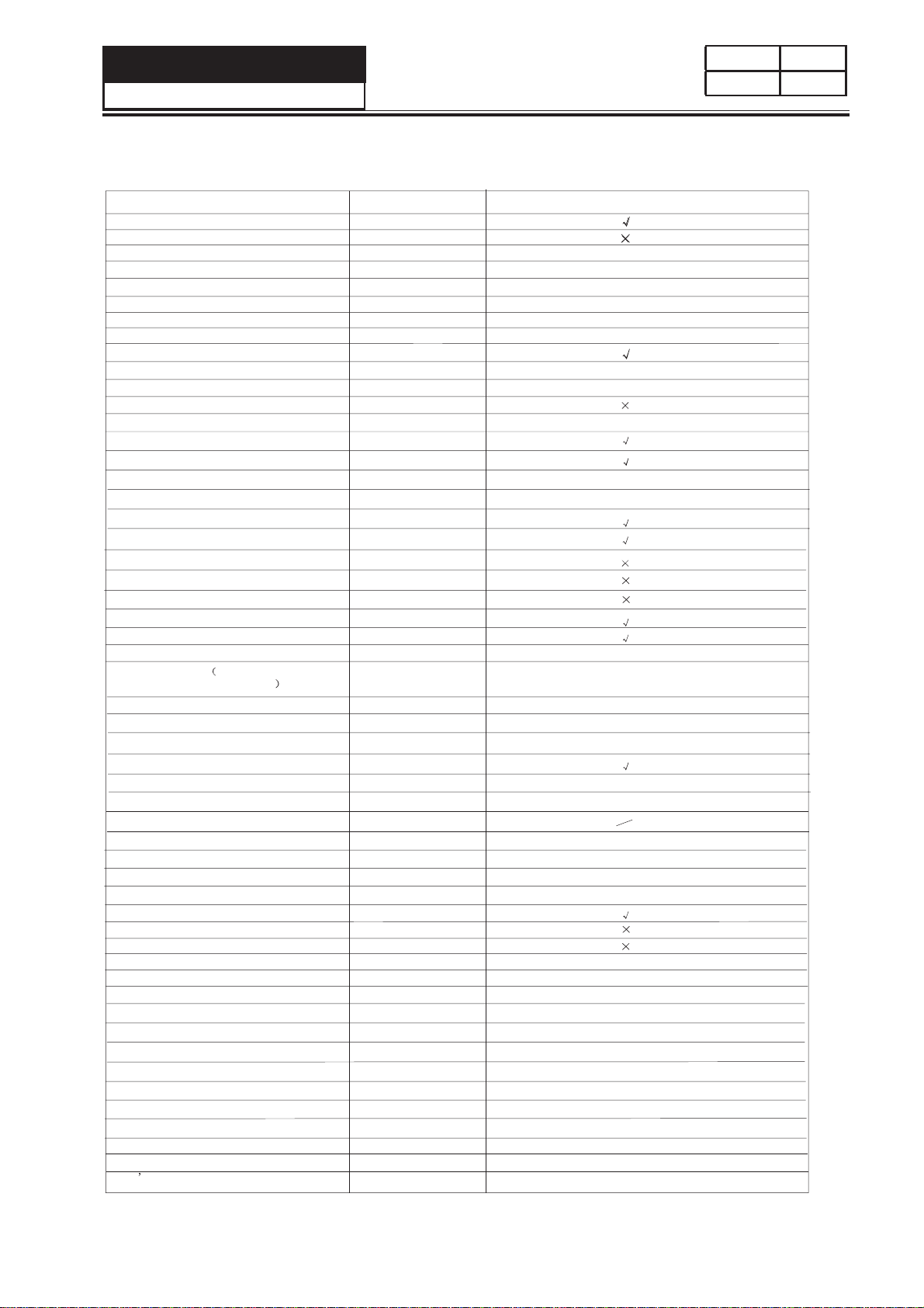
1-1. Table of Contents
Document control
Chapter 1. General Information ............................................................................... 2
2 stnetnoC fo elbaT.1-1
3 senilediuG lareneG.2-1
3slobmys gninraW dna noituaC.3-1
......................................................................................................... 1
Chapter 2. Product Feature
4serutaeF.1-2
5snoitacificepS.2-2
3slobmys noitacidni noitcnuF.4-1
....................................................................................... 4
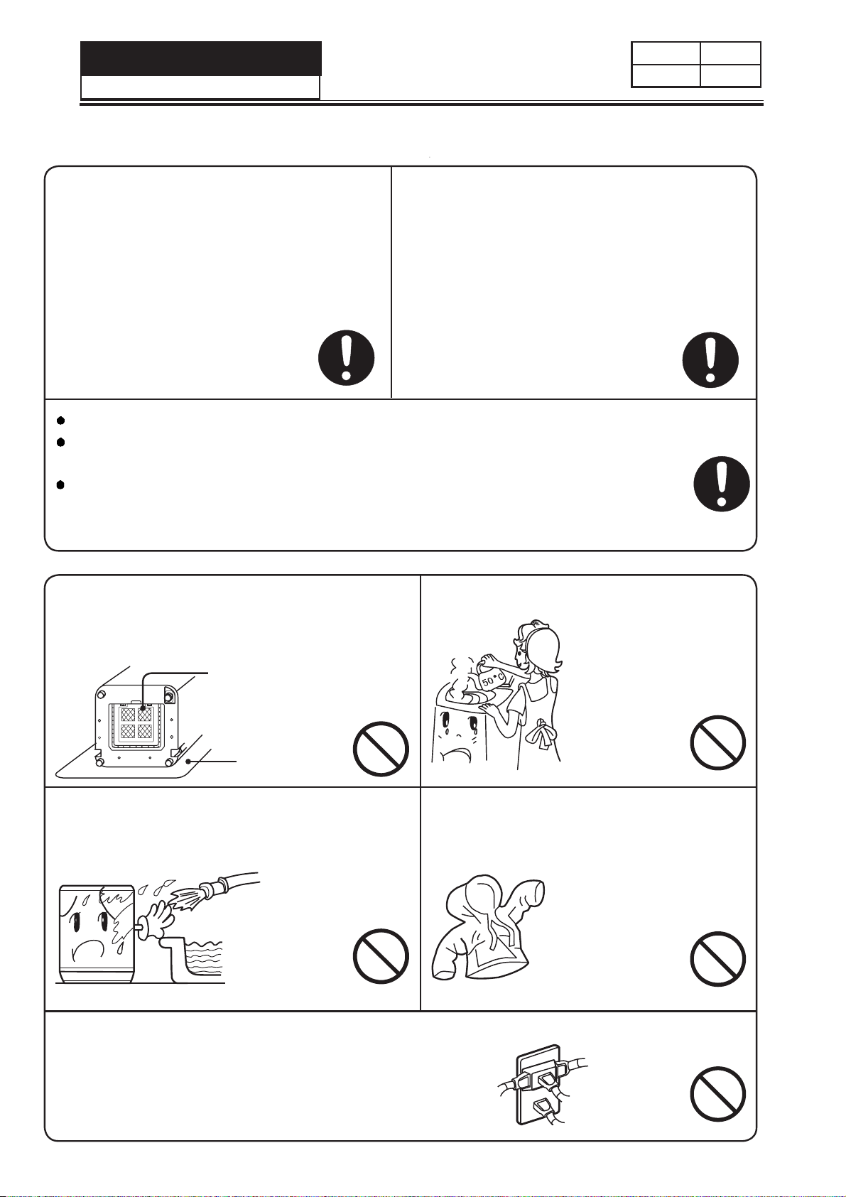
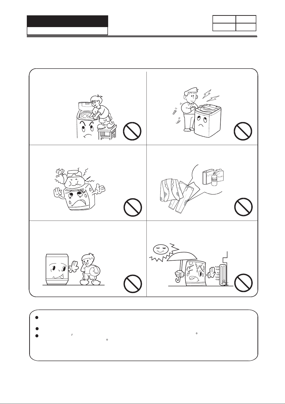
Chapter 3. Safety Precautions
3-1. Safety 6
7snoituac dna gninraW.2-3
Chapter 4. Installation and accessory parts .............................................................
6
8
4-2. Installation the button plate
4-3. Adjustment of the installation position
4-1. Key points in installation
4-4. Usage of operation buttons
4-7. Key points in disassembly
4-5. Product briefs
15
15
Chapter 6. Maintenance service and trouble shooting
.............................................
6-1.
6-2. Trouble shooting charts
6-2-1. No action(the indicator is off)
6-2-2. No water filling
6-2-3. No rotation in washing or(rotate to one direction)
6-2-4. No draining
6-2-5. Keep filling water
6-2-7. Too much spinning noise
6-2-6. No spinning
6-2-8. Too much noise in washing
6-2-9. The tub rotates to one direction(in washing)
6-2-10. Brake time out
Chapter 7. Wiring diagram .................................................................22
.........................
8snisnemiD teN.3-3
8
8
9
11
12
12
16
16
17
17
18
18
19
19
20
20
21
.......................................................................................
.......................................................................................
.....................................................................
.....................................................................
.....................................................................
.......................................................................................
.......................................................................................
.......................................................................................
.........................................................................................................
.......................................................................................
.......................................................................................
.......................................................................................
.......................................................................................
.........................................................................................................
.......................................................................................
.......................................................................................
.......................................................................................
14
Chapter 5. Parts and functions
...................................................................................
.......................................................................................
.......................................................................................
.......................................................................................
.......................................................................................
.......................................................................................
.......................................................................................
.......................................................................................
.......................................................................................
.......................................................................................
.......................................................................................
.......................................................................................
4-6. Adding washing powder 12
. ............................................................................................