Edwards M528-09-200 User manual

M528-09-840
Issue A Original
Instruction Manual
CXS Inlet Pressure Transmitter
Description Item Number
Inlet Pressure Transmitter M528-09-200

This page has been intentionally left blank.

© Edwards Limited 2013. All rights reserved. Page i
Edwards and the Edwards logo are trademarks of Edwards Limited.
Contents
M528-09-840 Issue A
Contents
Section Page
1 Introduction .......................................................................................1
1.1 Scope and definitions ................................................................................................... 1
1.2 Description ................................................................................................................ 1
2 Installation .........................................................................................3
2.1 Installation safety ....................................................................................................... 3
2.2 Cable and gland selection .............................................................................................. 3
2.3 Inlet pressure transmitter installation ............................................................................... 4
2.4 Pressure transmitter set-up ............................................................................................ 7
3 Operation ..........................................................................................8
3.1 Inlet pressure display ................................................................................................... 8
4 Maintenance .......................................................................................9
For return of equipment, complete the HS Forms at the end of this manual.
Illustrations
Figure Page
1 Pressure transmitter recommended locations (CXS dry pumps with and without flame arrestors) ......... 2
2 CXS control box and interface connector block ..................................................................... 2
3 CXS control box electrical connection ................................................................................ 4
4 Pressure transmitter electrical connections showing terminals T1 and T2 ..................................... 5
5a Cable installation routing recommendation (no flame arrestor) ................................................. 6
5b Cable installation routing recommendation (with flame arrestor) ............................................... 6
6 Pump Display Terminal (PDT) .......................................................................................... 7
Associated Publications
CXS Dry Pumps Instruction Manual M528-00-880
CXS_EH Combination Systems Instruction Manual M518-00-880
Technical Information (Endress+Hauser Instruments International) Cerabar M PMC51, PMP51, PMP55
TI00436P/00/EN/15.11 No. 71134874)
Trademark credits
Loctite®is a registered trademark of Henkel Corporation
cg/11/13

This page has been intentionally left blank.
M528-09-840 Issue A
Page ii © Edwards Limited 2013. All rights reserved.
Edwards and the Edwards logo are trademarks of Edwards Limited.

© Edwards Limited 2013. All rights reserved. Page 1
Edwards and the Edwards logo are trademarks of Edwards Limited.
Introduction
M528-09-840 Issue A
1Introduction
1.1 Scope and definitions
This manual provides installation, operation and maintenance instructions for the Edwards inlet pressure transmitter
accessory. The inlet pressuretransmitter must be used as specified in this manual. Read this manual before installing
and operating the transmitter.
Important safety information is highlighted as WARNING and CAUTION instructions; these instructions must be
obeyed. The use of WARNINGS and CAUTIONS is defined below.
CAUTION
Cautions are given where failure to observe the instruction could result in damage to the equipment, associated
equipment and process.
1.2 Description
The pressure transmitter is and Endress and Hauser Ex d device which can provide inlet pressure information to the
CXS dry pump for indication and control purposes. The pressure transmitter can be used for controlling pump pressure
using the CXS dry pump's PID control function. Once connected and set-up, it is possible to display pressure on a Pump
Display Terminal (PDT).
The inlet pressure transmitter is fitted to the CXS dry pump inlet spool above the inlet valve.
The PDT (part number D372-80-700) is available as an accessory and must be used for installation configuration.
CXS inlet pressure transmitter pack contents:
Pressure transmitter Endress and Hauser PMP51-BC21JB2KGBRKJA1+AA
Edwards instruction manual M52805860
Endress and Hauser PMP51 Instruction manual
WARNING
Warnings are given where failure to observe the instruction could result in injury or death to
people.
M528-09-840 Issue A
Page 2 © Edwards Limited 2013. All rights reserved.
Edwards and the Edwards logo are trademarks of Edwards Limited.
Introduction
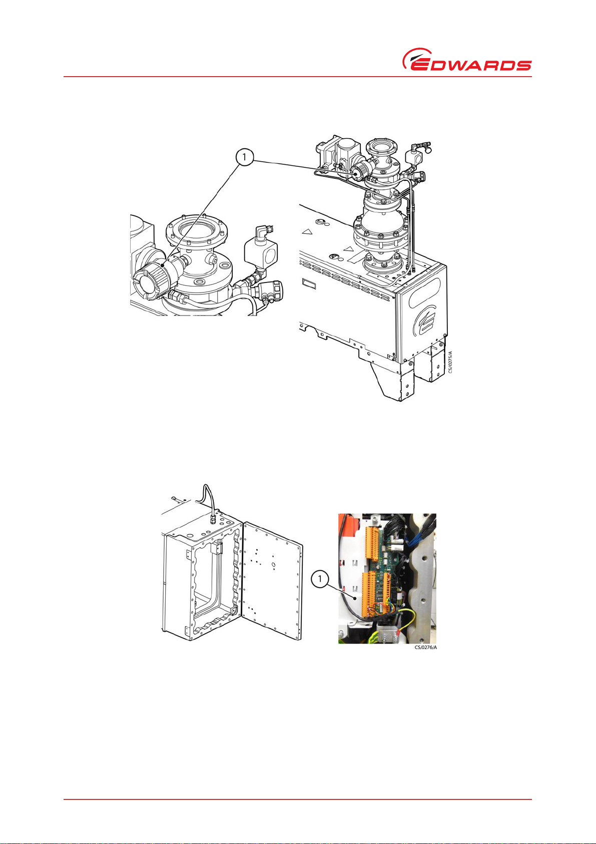
Figure 1 - Pressure transmitter recommended locations (CXS dry pumps with and without flame arrestors)
The cable connects the pressure transmitter to the interface connector block within the CXS control box.
Figure 2 - CXS control box and interface connector block
1. Pressure transmitter
1. Cable tray

© Edwards Limited 2013. All rights reserved. Page 3
Edwards and the Edwards logo are trademarks of Edwards Limited.
Installation
M528-09-840 Issue A
2 Installation
2.1 Installation safety
2.2 Cable and gland selection
The cable and cable glands are not provided. A cable and gland suitable for the instrument, control box and
environment must be selected in accordance with EN60079-14:2008.
WARNING
Isolate and lock-out the electrical supply. Allow 15 minutes before opening the CXS control box to
prevent potential ignition hazards being exposed to the hazardous area.
WARNING
The inlet spool should only be opened when the pump is switched off, isolated from the electrical
supply and in the absence of explosive atmosphere.
WARNING
The surfaces of the inlet can be very hot when the CXS system is running. Allow these surfaces to
cool to a safe temperature before installing the pressure transmitter.
WARNING
Ensure that the CXS dry pump and associated pipe-work is purged and isolate inlet and exhaust
before installation or replacement.
WARNING
Leak test the system after installation and seal leaks found to prevent leakage of dangerous
substances out and leakage of air into the system.
WARNING
Use appropriate personal protective equipment.
Personal protective equipment should be checked and used as specified by its supplier. Hazardous
chemicals that have been pumped are located within the pumps and piping. Edwards recommends
the use of suitable protective gloves and clothing along with a respirator if contact with substances
is anticipated. Particular caution should be exercised when working with fluorinated materials
which may have been exposed to temperatures greater than 260°C. Refer to Edwards Material
Safety Data Sheets for detailed information.
WARNING
The pressure transmitter and CXS Control box entries must be fitted with certified glands in
accordance with EN60079-14:2008, 10.4.2. Note that the CXS control box is over 2 dm3 and must
be fitted with a gland as specified in EN60079-14:2008, 10.4.2. e).
M528-09-840 Issue A
Page 4 © Edwards Limited 2013. All rights reserved.
Edwards and the Edwards logo are trademarks of Edwards Limited.
Installation
2.3 Inlet pressure transmitter installation
If the pump has previously been run on process, start by performing the following steps:
1. Allow the pump system to cool to a safe temperature before starting maintenance work.
2. Vent and purge the dry pumping system before starting installation or maintenance work.
3. Isolate and lock-out the dry pumping system and other components in the process system from the electrical
supply to prevent accidental operation. Allow 15 minutes before opening the CXS control box.
Note: The emergency stop switch on the dry pumping system is not an electrical isolator.
4. Remove the appropriate ½" BSP plug from the inlet spool above the inlet valve.
5. Coat the thread of the transmitter with Loctite®577 thread sealant or equivalent suitable for the process. Insert
the transmitter into the vacant port and secure.
6. Undo the 24 hex screws from the front of the CXS control box using a 6 mm hex drive and hinge open.
7. Remove blanking plug from the CXS control box, if fitted.
8. Fit the cable gland in the position shown in Figure 5a or 5b.
9. Thread the cable through the gland and along the cable tray as indicated in Figure 2. Secure the cable(s) to the
cable tray with cable ties. Wire into the terminals in the pump interface panel shown in Figure 3. Two channels
are available. 'Pressure 1' allows the analogue signal to be used for PID control, as well as visual indication on a
PDT. 'Pressure 2' only allows visual indication on a PDT.
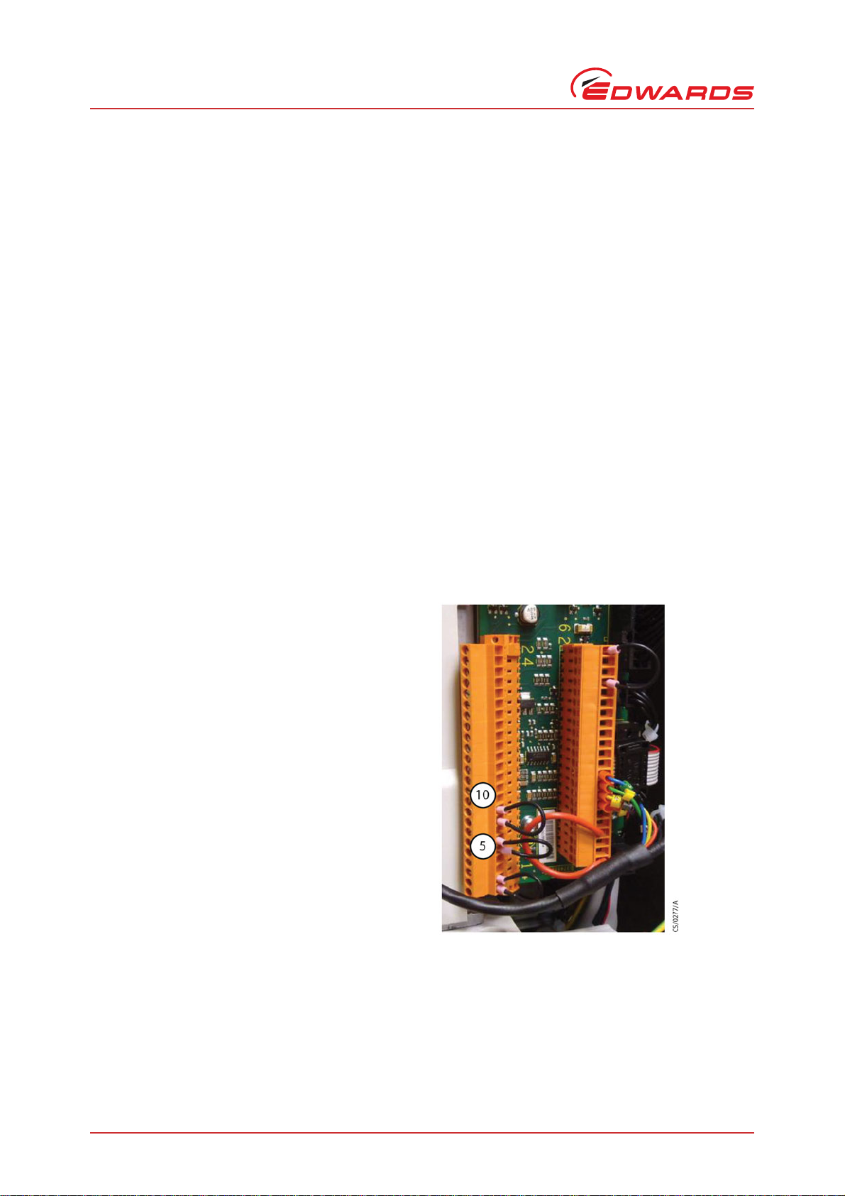
Figure 3 - CXS control box electrical connection
Note: Connections accept wires from 0.2 mm² to 1.5 mm² in solid conductor or 0.35 mm2fine stranded. If bootlace
ferrules are used, bootlace sizes 0.2 mm² to 1.5 mm² can be used. It is recommended, where possible, that
wires to be connected should be terminated with bootlace ferrules or solid conductors to avoid any free
stray wire strands.
Note: To make the connections use a small flat-blade screwdriver (screwdriver size blade 0.4 x 2.5 mm, tightening
to a torque of 0.2-0.25 Nm. Check that the connection is secure after tightening. The terminal blocks can
be removed for ease of wiring. Firmly plug back into place.
For connection to Pressure 1
channel, remove link wire between
8 and 9 and connect to terminals
9 and 10 (+24 V) 4-20 mA.
For connection to Pressure 2 channel
(monitoring only) remove link wire
between 5 and 6 and connect to
terminals 6 and 7 (+24 V).

© Edwards Limited 2013. All rights reserved. Page 5
Edwards and the Edwards logo are trademarks of Edwards Limited.
Installation
M528-09-840 Issue A
10.Tighten the gland according to the manufacturer’s instructions once there is sufficient cable length outside of
the pump enclosure for the transmitter or customer specific wiring.
11.Route the cable as suggested in Figure 5a and 5b to the pressure transmitter securing it appropriately.
12.Fit the cable gland to the pressure transmitter.
13.Undo the security clamp for the top cover of the pressure transmitter using an Allen key. Unscrew the top cover.
Unclip and disconnect the display unit so the terminals are exposed.
14.Feed the cable through the pressure transmitter gland and attach ferrules. Make the connections into the
pressure transmitter as shown in Figure 4.
15.Tighten the transmitter cable gland according to the manufacturer’s instructions and reassemble the transmitter
using step 11 in reverse.
16.Close the CXS control box door and screw in the door securing bolts. Torque the bolts to 30 Nm.
17.Connect an external earth to the grounding terminal on the pressure transmitter as shown in Figure 4.
18.Perform a leak test before operating the pump.
Figure 4 - Pressure transmitter electrical connections showing terminals T1 and T2
1. External grounding terminal
2. Terminals
M528-09-840 Issue A
Page 6 © Edwards Limited 2013. All rights reserved.
Edwards and the Edwards logo are trademarks of Edwards Limited.
Installation
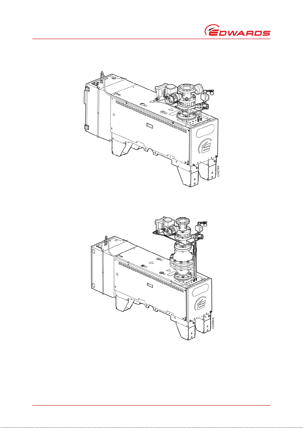
Figure 5a - Cable installation routing recommendation (no flame arrestor)
Figure 5b - Cable installation routing recommendation (with flame arrestor)

© Edwards Limited 2013. All rights reserved. Page 7
Edwards and the Edwards logo are trademarks of Edwards Limited.
Installation
M528-09-840 Issue A
2.4 Pressure transmitter set-up
CAUTION
Configuration changes made using the PDT should be performed with the pump not running. It is recommended
that the CXS dry pump is then power-cycled following configuration changes.
The Pump Display Terminal (PDT) must be used to configure the pressure transmitter. The PDT must be connected
and used in accordance with the instructions in the CXS instruction manual M528-00-880.
Figure 6 - Pump Display Terminal (PDT)
The system should be switched on and the PDT plugged in.
Once the PDT is powered up, set up the inlet pressure transmitter as follows:
1. Press 'setup' - scroll using arrow keys to 'Service' and press 'enter'.
2. Scroll to 'fit accessory' and press 'enter'.
3. If the transmitter is wired into the channel for 'Pressure 1' then scroll to 'Pressure 1', press 'enter' then select
'fitted' using arrow keys and press 'enter'. If the transmitter is wired into the channel for 'Pressure 2' then scroll
to 'Pressure 2', press 'enter' then select 'fitted' using arrow keys and press 'enter'.
4. Scroll to either 'Max pressure 1' or 'Max pressure 2' (depending on which one has been fitted - see step 3), press
'enter'. Using the 'cancel' and 'enter' keys to move the cursor left and right, and the arrow keys to change the
digits, set the Max Pressure to 2000mbar. Press 'enter' several times to move the cursor all the way to the right,
and then once more to confirm.
5. To exit the menu press the 'cancel' key three times where the light will revert to normal.
WARNING
The Pump Display Terminal (PDT) is a non-Ex device, unsuitable for use in hazardous areas. It must
be connected using suitable cabling according to EN60079-14, routed into a safe area. Refer to
Section 4.8 for relevant safety information regarding connections to the customer interface.
WARNING
The test/diagnostics port on the Ex d control box door is intended for connection to a PDT for
commissioning, service and diagnostics purposes, only when: the CXS dry pump is installed in a safe
area, or if safety within the hazardous area can be guaranteed, for example by the use of a suitable
gas detector to ensure the absence of explosive atmosphere.
After the PDT socket has been used, the explosion-proof stopping-plug must be refitted. Check the
condition of the threads and O-ring, tighten hand-tight then a further half turn with wrench.
Incorrect use of the PDT socket and PDT will invalidate the explosion-proof rating of the CXS dry
pump and may result in an explosion of the hazardous area.

M528-09-840 Issue A
Page 8 © Edwards Limited 2013. All rights reserved.
Edwards and the Edwards logo are trademarks of Edwards Limited.
Operation
3 Operation
3.1 Inlet pressure display
Inlet pressure is automatically displayed on a PDT (if fitted) after correct setup.

© Edwards Limited 2013. All rights reserved. Page 9
Edwards and the Edwards logo are trademarks of Edwards Limited.
Maintenance
M528-09-840 Issue A
4Maintenance
The wiring should be checked at regular intervals. If damage is found it should be rectified immediately.
Refer to the manufacturers instruction manual for maintenance of the inlet pressure transmitter.

M528-09-840 Issue A
Page 10 © Edwards Limited 2013. All rights reserved.
Edwards and the Edwards logo are trademarks of Edwards Limited.
This page has been intentionally left blank.

Return the equipment or components for service
Before you send your equipment to us for service or for any other reason, you must send us a
completed Declaration of Contamination of Vacuum Equipment and Components – Form HS2. The
HS2 form tells us if any substances found in the equipment are hazardous, which is important for
the safety of our employees and all other people involved in the service of your equipment. The
hazard information also lets us select the correct procedures to service your equipment.
We provide instructions for completing the form in the Declaration of Contamination of Vacuum
equipment and Components – Procedure HS1.
If you are returning a vacuum pump, note the following:
If a pump is configured to suit the application, make a record of the configuration before
returning the pump. All replacement pumps will be supplied with default factory settings.
Do not return a pump with accessories fitted. Remove all accessories and retain them for
future use.
The instruction in the returns procedure to drain all fluids does not apply to the lubricant in
pump oil reservoirs.
Download the latest documents from www.edwardsvacuum.com/HSForms/, follow the procedure in
HS1, fill in the electronic HS2 form, print it, sign it, and return the signed copy to Edwards.
Note: If we do not receive a completed HS2 form, we will not accept the return of the
equipment.
P80081000, Issue A

P800‐80‐000IssueT
edwardsvacuum.com
Table of contents
Other Edwards Transmitter manuals


Popular Transmitter manuals by other brands

Lightware
Lightware SW4-OPT-TX240RAK quick start guide

SmartSight
SmartSight S1000-RX 1 user manual

dji
dji SRW-60G user manual

aci
aci B5C Installation, operation and maintenance manual

ACR Electronics
ACR Electronics ELT-202 EMERGENCY LOCATOR TRANSMITTER Product support manual

Abilia
Abilia Progress PC manual

Adtech
Adtech TCT-327-MOD instruction manual

R.V.R. Elettronica
R.V.R. Elettronica PTX-LCD user manual

Kensington
Kensington LiquidFM K33411US Instruction guide

RKI Instruments
RKI Instruments 65-2645XL0504SS Operator's manual

Sony
Sony DWT-P30 operating instructions

Jäger Direkt
Jäger Direkt OPUS RADIO PLUS operating instructions


