Eedomus TSE03-JOEL User manual
1
IER
I: Inclusion
: Exclusion
E
: Reset
R
Rear View Inside View
6
5
Side View
Front View
Side View
1
2
4
Bottom View FIGURE 2
3
TSE03-JOEL
TAC06-JOEL DOOR BELL & PUSH BUTTON
General Introduction
The Wireless Door Bell & Push Button are a pair of Z-WaveTM enabled devices
displaying the Z-WaveTM logo, operating at 868.42 MHz. Taking the role of a
transmitter and a small Z-Wave controller, the Push Button sends signals of bell
triggering to Door Bell (receiver) wirelessly after Button is pressed. The Push Button
is compatible with other Z-Wave enabled devices.
The front buttons on Door Bell and Push Button provide not only the function of
pressing but also the function of LED indication. Preset songs (5 by default) of Door
Bell are available for sound selection, but it is also customizable as you can play own
music by replacing it with your own WAV file.
The Door Bell is powered by 3 x AA 1.5V alkaline batteries and the Push Button is
powered by 2 x AAA 1.5V alkaline batteries. When battery level drops below an
unacceptable level, the LED on Bell will flash once every 30 seconds and flash while a
song is playing, whereas the LED on Push Button will flash when Button is pressed.
When this occurs, please replace the batteries as soon as possible.
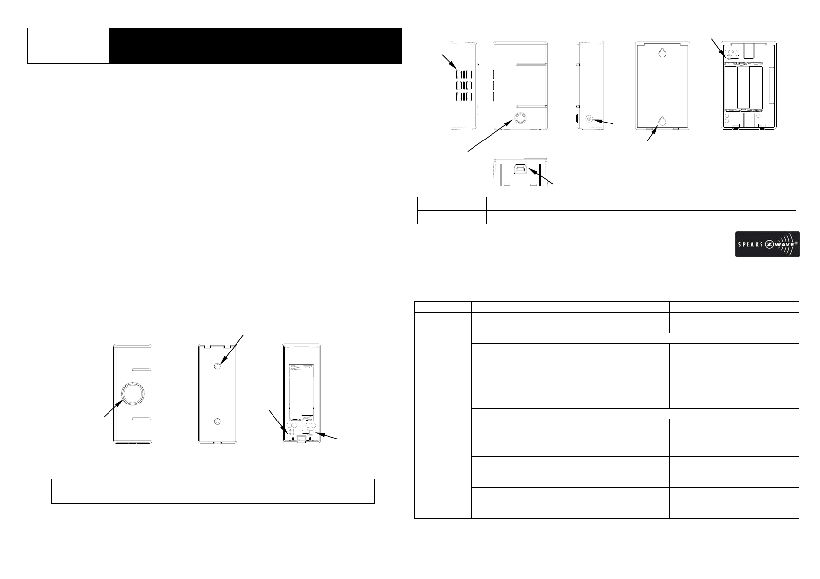
Product Overview
Push Button
1LED Indicator/Button 3○
I○
RKey
2Holes for Wall Mounting 4○
A○
EKey
Door Bell
1Horn 2LED Indicator/Music Selector 3DC Jack
4USB Port 5Keyhole Slot 6○
I○
E○
RKey
Z-WaveTM Network
The kit utilizes Z-Wave technology where Push Button is the controller and Bell is
Z-Wave enabled slave device in the system. Please refer to the table below for
carrying out inclusion, exclusion, reset or association.
Function Description LED Indication
No node ID The Z-Wave Controller (Push Button) does not
allocate a node ID to the Door Bell. Door Bell:
2-second on, 2-second off.
To include Push Button as a Primary Controller
1. To have Push Button entered inclusion
mode, press ○
I○
RKey 3 times (within 1.5
secs).
Push Button:
0.5-second on, 0.5-second off.
2. Press ○
I○
E○
RKey of Door Bell 3 times
(within 1.5 secs).
Door Bell:
0.3-second on after ○
I○
E○
Ris
pressed.
To include Push Button as a Secondary Controller
1. To have Controller entered inclusion mode.
2. Press and hold ○
I○
RKey of Push Button for
10 secs. Push Button:
0.1-second on, 0.8-second off.
Success Push Button:
Red LED of Push Button is on
for 1 sec.
Inclusion
Failure Push Button:
Red LED of Push Button
flashes 3 times rapidly.
I A
RE
1
Front View
2
Rear View
3
4
Inside View
FIGURE 1

2
IER
I: Inclusion
: Exclusion
E
: Reset
R
Door Bell
(inside view)
○
I= Inclusion
○
E= Exclusion
○
R= Reset
I A
RE
○
I= Inclusion
○
R= Reset
○
E= Exclusion
○
A= Association
Quick Guide
The kit utilizes Z-Wavetechnology. Please get familiar with the terms below before
starting the operations.
Function Abbrev. Description
Inclusion ○
IAdd a Z-Wave enabled device (e.g. Push Button) to Z-Wave
network. To control the Door Bell by using the Push Button, you
must add both of them to the network by executing Inclusion.
Exclusion ○
EDelete a Z-Wave enabled device (e.g. Door Bell) from the network.
Association ○
AAfter inclusion, you have to define the relationship between devices.
Trough association, device can be assigned as master/slave, and
specify which slave is going to be controlled by which master.
Reset ○
RClear all the data.
Note: In Push Button, each button is designed for 2 functions, e.g. ○
I○
EKey is for
inclusion and reset & ○
A○
EKey is for association and exclusion. As for Door Bell,
one button (○
I○
E○
RKey) covers all functions.
○
I= Inclusion
To include Push Button as a Primary Controller…
Push Button:
Press ○
I○
RKey 3 times (within 1.5 secs), LED flashes on & off alternately.
Door Bell:
Press ○
I○
E○
RKey 3 times (within 1.5 secs).
To include Push Button as a Secondary Controller…
Put Controller (primary controller) into Inclusion mode.
Push Button (secondary):
Press and hold ○
I○
RKey for 10 secs, LED flashes on & off alternately.
Success: Red LED of Push Button is on for 1 sec.
Failure: Red LED of Push Button flashes 3 times rapidly.
○
E =Exclusion
Push Button:
Press ○
A○
EKey 3 times (within 1.5 secs), and within 1 sec, press ○
A○
EKey
again for 5 secs until LED is off; LED flashes on & off alternately for 30 secs.
Door Bell:
Press ○
I○
E○
R3 times (within 1.5 secs).
Success: Red LED of Push Button is on for 1 sec.
Failure: Red LED of Push Button flashes 3 times rapidly.
○
A =Association
Push Button is compatible with other Z-Wave enabled devices. Please ensure
they have completed inclusion before association.
Press ○
A○
EKey 3 times (within 1.5 secs), LED flashes on & off alternately for
30 secs. Put Z-Wave enabled device (slave) into association mode first, and
then put another Z-Wave enabled device (master) into association mode
afterwards.
Success: Red LED of Push Button is on for 1 sec.
Failure: Red LED of Push Button flashes 3 times rapidly.
○
R =Reset
Push Button:
Press ○
I○
RKey 3 times (within 1.5 secs), and within 1 sec, press ○
I○
RKey
again for 5 secs until LED is off; LED flashes on & off alternately for 30 secs. All
device data is cleared.
Door Bell:
Press ○
I○
E○
RKey 3 times (within 1.5 secs), and within 1 sec, press ○
I○
E○
R
Key again for 5 secs until LED is off. The data got from Push Button is cleared.
IMPORTANT NOTE:
If only one Door Bell is to be deleted from the Push Button, please execute Exclusion.
Try not to reset Door Bell and Push Button unless you wish to clear all the data. Make
sure to reset BOTH Door Bell and Push Button, otherwise a time delay (the Bell takes
awhile to sound after you pressed the Push Button) might occur if you do the inclusion
again. After reset, the connection between Push Button and Door Bell is disconnected.
The Door Bell will not chime if you pr
ess the Push Button.

3
Function Description LED Indication
1. To have Push Button entered
exclusion mode, press ○
A○
EKey
3times (within 1.5 secs).
2. Within 1 sec, press ○
A○
EKey
again for 5 secs until LED is off.
Push Button:
0.1-second on, 0.8-second off.
3. Press ○
I○
E○
RKey of Door Bell 3
times (within 1.5 secs). Door Bell:
0.3-second on after ○
I○
E○
Ris
pressed.
Success
(node ID has been excluded) Push Button:
Red LED of Push Button is on
for 1 sec.
Exclusion
Failure/Time Out Push Button:
Red LED of Push Button
flashes 3 times rapidly.
Push Button:
1. Press ○
I○
R3 times (within 1.5
secs).
2. Within 1 sec, press ○
I○
RKey
again for 5 secs until LED is off.
3. All device data is cleared.
Push Button:
0.5-second on, 0.5-second off.
Door Bell:
1. Press ○
I○
E○
R3 times (within 1.5
secs).
Door Bell:
0.3-second on after ○
I○
E○
Ris
pressed.
2. Within 1 sec, press ○
I○
E○
RKey
again for 5 secs until LED is off.
3. The data got from Push Button is
cleared.
Door Bell:
LED stays on until Reset is
executed.
IDs are excluded. Push Button:
Red LED of Push Button is on
for 1 sec.
Reset
After you’ve reset both Door Bell and Push Button, the connection
between Push Button and Door Bell is disconnected. The Door Bell will
not chime if you press the Push Button.
Push Button is compatible with other Z-Wave enabled devices. Please
ensure they have completed inclusion before association.
Press ○
A○
E3 times (within 1.5 sec).
Push Button:
0.5-second on, 0.5-second off.
Put Z-Wave enabled device (slave) into association mode first, and then
put another Z-Wave enabled device (master) into association mode
afterwards.
Success Push Button:
Red LED of Push Button is on
for 1 sec.
Association
(Push Button only)
Failure/Time Out Push Button:
Red LED of Push Button
flashes 3 times rapidly.
Including a node ID allocated by Z-Wave Controller (Push Button) means inclusion.
Excluding a node ID allocated by Z-Wave Controller means exclusion.
Please also note:
Push Button
1. Z-Work network supports multiple controllers so you can use additional Push
Buttons throughout the home, however, there can only be one controller acts as
primary with the rest of controllers considered as secondary. Primary controller is
the main controller which can be used to set up and control your Z-Wave network;
it must be used to include/exclude devices. Secondary controllers are supportive
controllers which are same brand and model as Primary Controller, except they
cannot include/exclude devices.
2. If a secondary controller is to be added to the network, please ensure to have
primary controller (e.g. Push Button) and device (e.g. Door Bell) complete
inclusion first, and then include secondary controller (e.g. another Push Button) to
the network afterwards.
3. If Push Button is set as a secondary controller, operation of inclusion, exclusion
and association will be disabled except reset is still retained. To discharge the
role of a secondary controller, you can…
a. Have Primary Controller enter exclusion, and than put the Push Button
into inclusion mode by pressing and hold ○
I○
RKey of Push Button for 10 secs.
b. Reset the Push Button.
Door Bell
The Door Bell will stay “awake” for ten minutes when power is first supplied and four
minutes after exclusion and reset to allow time for configuration.
Choosing a Mounting Location
When choosing a suitable location for Push Button and Door Bell, the following points
should be considered.
Push Button
1. The Push Button is suitable for mounting on doorjamb of the front door or a wall.
2. Position the Push Button in an easily accessible position and outdoor only.
Door Bell
1. The Door Bell is suitable for mounting on doorjamb of the front door or a wall; it
can also be free standing for it to be placed and moved as need or in a place
where the sound can be heard clearly.

4
2. It is recommended to position the Door Bell indoor only in an easily accessible
position so the Bell can be connected to a computer if necessary.
Installation
Push Button
1. Insert a flat bladed screwdriver into the slot at the bottom of the Push Button.
Lever the cover and base apart (FIGURE 3).
2. Fit two 1.5V AAA batteries supplied to the battery compartment (FIGURE 4).
Please note, the adoption of alkaline battery is highly recommended as it would
last longer.
FIGURE3 FIGURE4
3. Mount the Push Button directly on to your door jamb or wall using adhesive strips
or screws provided. Make sure the surface of the doorjamb or wall is clean.
If fixing the Push Button with screws; hold the rear cover in position and drill two
mounting holes. Insert the supplied plastic wall plugs, and then screw the rear
cover to the wall using the supplied screws.
FIGURE 5
4. Refit the Push Button to the rear cover.
Door Bell
1. Insert a flat bladed screwdriver into the slot at the bottom of the Door Bell. Lever
the cover and base apart (FIGURE 6).
2. Fit three 1.5VAA batteries supplied to the battery compartment. Please note, the
adoption of alkaline battery is highly recommended as it would last longer
(FIGURE 7).
FIGURE6 FIGURE7
3. Decide to let the Bell freestanding or wall mounted. If wall mounting is
preferred…
Use the fixing template provided to mark the position of two fixing holes on
the wall. Drill two holes at the marked locations, insert the supplied plastic wall
plugs and then fit two screws into the wall plugs until almost fully home. Hang the
rear cover over these screws using the two keyhole slots (FIGURE 8).
FIGURE 8
4. Engage the Door Bell to the rear cover.
Door Bell
Fixing Template
5
Operation
To sound the Bell, you can press the Button of Push Button. The Red LED of Push
Button is on steadily while the signal is sending. You can also press the Music
Selector of the Door Bell to sound the Bell.
WAV is the only file type that can be played by Door Bell. To download songs to Door
Bell, please execute Door Bell.exe. Before you install the program, make sure your
computer meets or exceeds these requirements:
*Win2K / XP32 / XP64 / Vista32 / Vista64 * USB 1.1
Please follow the steps below in sequence to execute the program.
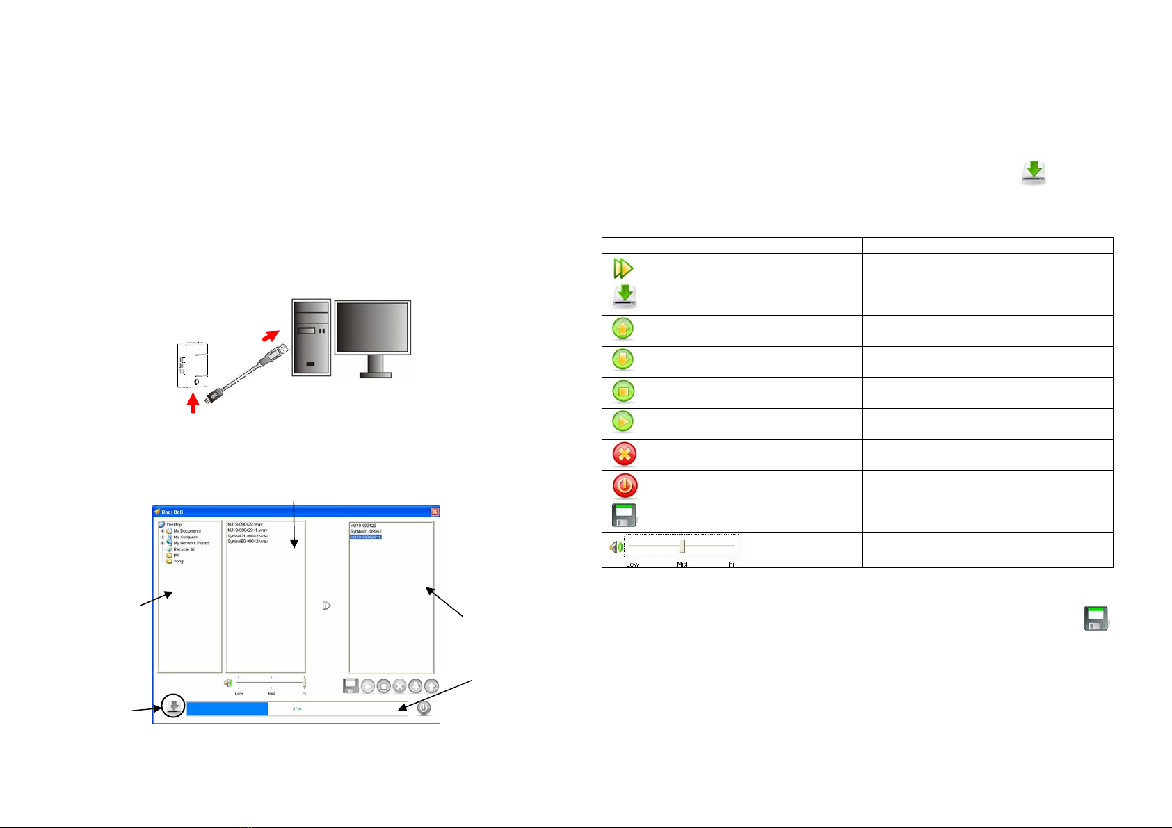
1. Plug one end of USB cable into the Bell, and the other end into an open USB port
of your computer.
2. The Door Bell.exe will auto run. If it doesn’t, please double click on Door Bell.exe
under USB drive to execute the program.
3. A user interface will display; it contains three parts of panes: Navigation Pane, List
Pane and Clipboard.
Navigation Pane: Displays a list of files those are placed on the desktop. In the
Look In drop-down list, select the folder where the songs are
stored.
List Pane: It unfolds the folder you’ve selected in Navigation Pane; a list of
songs stored in the folder is displayed.
Clipboard: A temporary storage area for selected songs. They will be
downloaded to the Bell once Download Key (as shown in
FIGURE 10) is pressed.
The table below shows a list of keys and key functions.
Key Name of Key Function
Add Add a selected song to the playlist of
Clipboard
Download Download songs from Clipboard to
Door Bell
Move Up Move selected song/songs one space
up in the playlist of Clipboard
Move Down Move selected song/songs one space
down in the playlist of Clipboard
Stop Stop playing the selected song
(Clipboard only)
Play Play the selected song
(Clipboard only)
Delete Delete a song from the playlist
(Clipboard only)
Exit Exit Door Bell.exe
Save As Save selected songs to another
directory or location
Volume Control
(Low / Mid / Hi) Adjusts the volume of songs; it
determines the volume of Door Bell
If you wish to keep the preset songs, it is recommended you make a copy of them
before carrying out the following steps. To save the preset songs, press ; to
download songs to Door Bell:
1. Select a folder where the songs are stored in Navigation Pane.
2. Select song/songs you wish to download to the Bell from List Pane.
FIGURE 9
List Pane
Clipboard
Navigation
Pane
Capacity
Indicator
Download
FIGURE 10
6
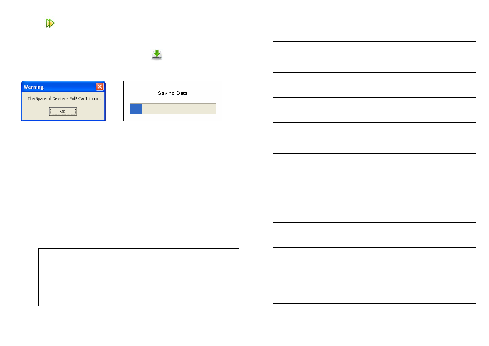
3. Press to add selected song/songs to the Clipboard. If storage capacity in
Clipboard has exceeded the limit, a warning indication will be shown (FIGURE 11);
likewise, you can refer to the capacity indicator for the percentage of being
occupied storage.
4. Once you’ve completed song selections, press to download selected songs
to the Bell. A saving prompt box will appear while data is saving (FIGURE 12).
FIGURE11 FIGURE12
Advanced Operation (Programming)
To following information is for someone that has some experience setting up a Z-Wave
system or someone that has computer software running a Z-Wave Controller.
Through Controller, you can enquire the current status of Door Bell or set the Door Bell
to return reports according to the settings as below.
1. Supported Z-Wave Commands
Door Bell will respond to BASIC and BINARY commands that are part of the
Z-Wave system.
1-1 BASIC_GET / SWTICH _ BINARY _GET / SENSOR_BINARY_GET
Upon receipt of the following commands from a Z-Wave Controller, the Door
Bell will report its current status (playing/ NOT playing) to the Controller.
BASIC_GET Command
[Command Class Basic, Basic Get]: enquire the current status of the Door
Bell, i.e. Door Bell is playing or not playing a song currently.
BASIC_REPORT Command
[Command Class Basic, Basic Report, Value = 0(0x00)]:report Door Bell
is not playing.
[Command Class Basic, Basic Report, Value = 255(0xFF)]: report Door
Bell is playing a song currently.
SWITCH BINARY GET Command
[Command Class Switch Binary, Switch Binary Get]: enquire the current
status of the Door Bell, i.e. Door Bell is playing or not playing a song
currently.
SWITCH BINARY REPORT Command
[Command Class Switch Binary, Switch Binary Report, Value =0(0x00)]:
report Door Bell is not playing
[Command Class Switch Binary, Switch Binary Report, Value =
255(0xFF)]: report Door Bell is playing a song currently.
SENSOR_BINARY_GET is equivalent to SWITCH_BINARY_GET;
SENSOR_BINARY_REPORT is equivalent to SWITCH_BINARY_REPORT.
SENSOR BINARY GET Command
[Command Class Sensor Binary, Sensor Binary Get]: enquire the current
status of the Door Bell, i.e. Door Bell is playing or not playing a song
currently.
SENSOR BINARY REPORT Command
[Command Class Sensor Binary, Sensor Binary Report, Value =0(0x00)]:
report Door Bell is not playing
[Command Class Sensor Binary, Sensor Binary Report, Value =
255(0xFF)]: report Door Bell is playing a song currently.
1-2 BASIC_SET / SWTICH _ BINARY _SET
Upon receipt of the following commands from a Z-Wave Controller, the Door
Bell can be set to playing / NOT playing.
[Command Class Basic, Basic Set, Value = 0(0x00)]: Set the Door Bell to
stop playing.
[Command Class Basic, Basic Set, Value = 255(0xFF)]: Set the Door Bell
to play.
[Command Class Switch Binary, Switch Binary Set, Value = 0(0x00)]:
Set the Door Bell to stop playing.
[Command Class Switch Binary, Switch Binary Set, Value = 255(0xFF)]:
Set the Door Bell to play.
1-3 BATTERY_GET / BATTERY REPORT
You can also enquire the battery status of the Bell by sending BATTERY_GET
command via controller. Once Bell receives the command, it will return
BATTERY_REPORT command.
BATTERY_REPORT Command
[Command Class Battery, Battery Report, Battery Level =20%-100%]
7
If it displays with a message of “Battery Level = 255(0xFF)”, it implies that the
Bell is at low battery status. Please replace the batteries as soon as
possible.
2. Z-Wave’s Groups (Association Command Class Version 2)
Door Bell can be set to send reports to associated Z-Wave devices. It supports
one association group with 5 nodes.
2-1 ASSOCIATION_GET
ASSOCIATION_GET Command
[Command Class Association, Association Get]: enquire Door Bell about
relevant information of Grouping 1.
ASSOCIATION_REPORT Command
[Command Class Association, Association Report]: report relevant
information of Grouping 1.
ASSOCIATION_GROUPING_GET Command
[Command Class Association, Association Grouping Get]: enquire how
many Groupings can be supported by the Door Bell.
ASSOCIATION_GROUPING_REPORT Command
[Command Class Association, Association Grouping Report]: report
Door Bell can support 1 Grouping.
2-2 ASSOCIATION_SET
ASSOCIATION_SET Command
[Command Class Association, Association Set]: decide which note
is/nodes are to be placed in Grouping 1.
2-4 ASSOCIATION_REMOVE (V2)
ASSOCIATION_REMOVE (V2) Command
[Command Class Association, Association Remove]: decide which note
is/nodes are to be excluded from Grouping 1 of Door Bell.
Note:
1. If the Door Bell is changing playing status (e.g. from NOT playing to playing), the
Door Bell will report its status (SENSOR_BINARY_REPORT) to nodes of
Grouping 1.
2. If battery level of Door Bell drops to an unacceptable level, the Door Bell will emit
BATTERY_REPORT “Battery Level = 255 (0xFF)” to the nodes of Grouping 1.
3. Command Class
The Door Bell supports Command Classes including…
* COMMAND_CLASS_BASIC
* COMMAND_CLASS_VERSION
* COMMAND_CLASS_BATTERY
* COMMAND_CLASS_SWTICH_BINARY
* COMMAND_CLASS_SENSOR_BINARY
* COMMAND_CLASS_ASSOCIATION_V2
* COMMAND_CLASS_MANUFACTURER_SPECIFIC
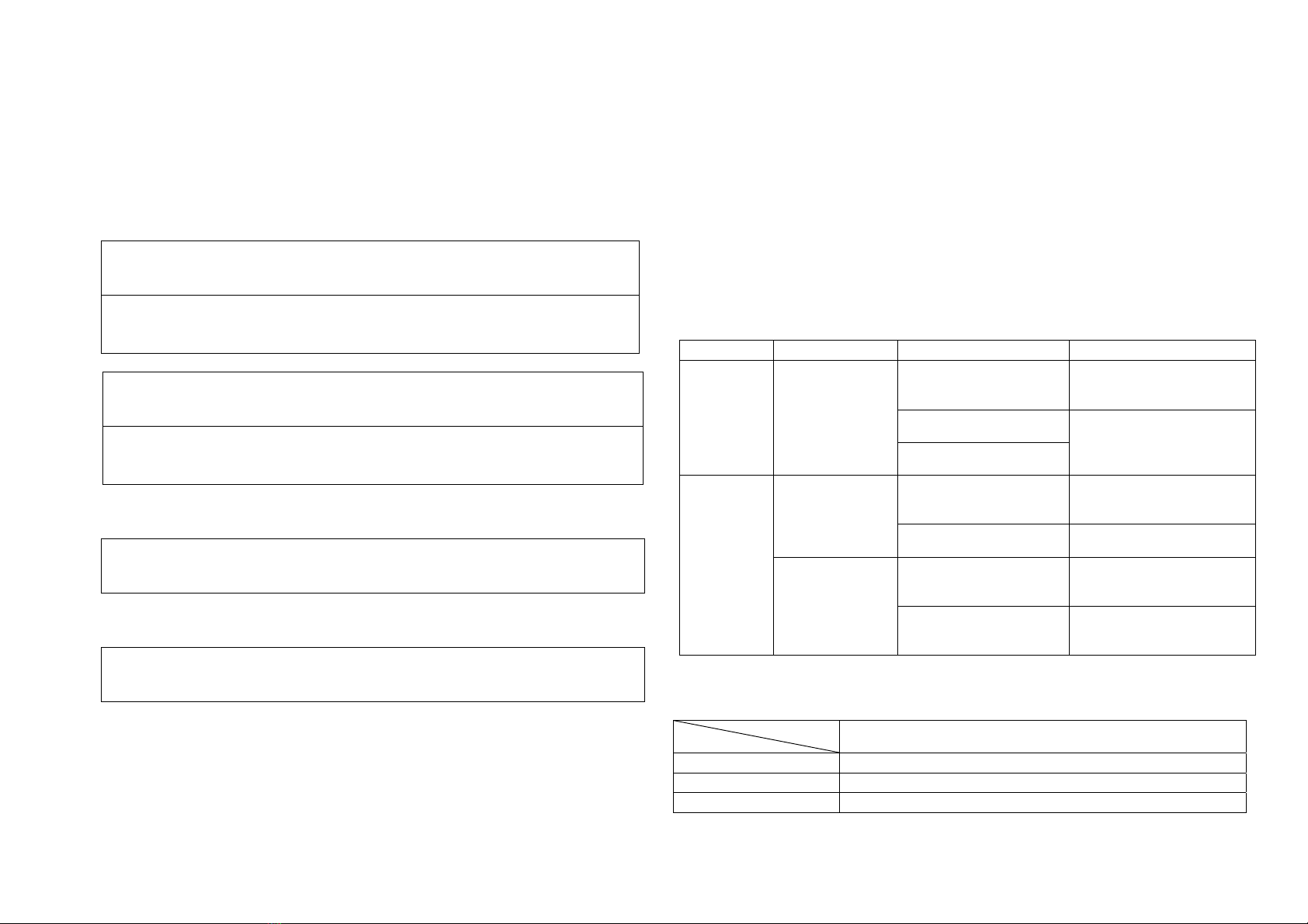
Troubleshooting
Device Symptom Possible Cause Recommendation
Run out of battery power
or does not fit batteries 1. Replace a new battery
2. Refit the battery with
correct polarity
Button or LED is
damaged
Push Button
LED indicator is
not working after
Button is
pressed The device is not
working
Call to the local service for
repair
Run out of battery power
or does not fit batteries 1. Replace a new battery
2. Refit the battery with
correct polarity
Bell doesn’t
sound after
Music Selector is
pressed The button is damaged Call to the local service for
repair
The user hasn’t logged
in to the Administrator Log in to Administrator to
execute the program
Door Bell
Door Bell.exe
cannot be
executed
Being blocked by
antivirus software or
firewall
Close the firewall or
antivirus software
Specifications
Model No.
Item
TAC06-JOEL Push Button
Battery 1.5V AAA size x 2
Range Up to 30 m line of sight
Frequency Range 868.42 MHz

8
Model No.
Item
TSE03-JOEL Door Bell
Power Adaptor 6V DC/600mA
Battery 1.5V AA size x 3
Range Up to 30 m line of sight
Frequency Range 868.42 MHz
*Specifications are subject to change without notice
Federal Communication Commission Interference Statement
This equipment has been tested and found to comply with the limits for a Class B
digital device, pursuant to Part 15 of the FCC Rules. These limits are designed to
provide reasonable protection against harmful interference in a residential installation.
This equipment generates, uses and can radiate radio frequency energy and, if not
installed and used in accordance with the instructions, may cause harmful interference
to radio communications. However, there is no guarantee that interference will not
occur in a particular installation. If this equipment does cause harmful interference to
radio or television reception, which can be determined by turning the equipment off
and on, the user is encouraged to try to correct the interference by one of the following
measures:
-Reorient or relocate the receiving antenna.
-Increase the separation between the equipment and receiver.
- Connect the equipment into an outlet on a circuit different from that to which the
receiver is connected.
- Consult the dealer or an experienced radio/TV technician for help.
This device complies with Part 15 of the FCC Rules. Operation is subject to the
following two conditions: (1) This device may not cause harmful interference, and (2)
this device must accept any interference received, including interference that may
cause undesired operation.
FCC Caution: Any changes or modifications not expressly approved by the party
responsible for compliance could void the user's authority to operate this equipment.
This transmitter must not be co-located or operating in conjunction with any other
antenna or transmitter.
WARNING:
Do not dispose of electrical appliances as unsorted municipal waste, use separate
collection facilities.
Contact your local government for information regarding the collection systems
available.
If electrical appliances are disposed of in landfills or dumps, hazardous substances
can leak into the groundwater and get into the food chain, damaging your health and
well-being.
When replacing old appliances with new once, the retailer is legally obligated to take
back your old appliance for disposal at least for free of charge.
This manual suits for next models
1
Table of contents
Popular Accessories manuals by other brands


Endress+Hauser
Endress+Hauser Deltabar S PMD70 Exchange instruction

Frank van Dijk Trading
Frank van Dijk Trading V069 instruction manual

Time2
Time2 Arthur Startup guide

Medisana
Medisana AD 635 operating instructions

VOLTCRAFT
VOLTCRAFT PB-9 operating instructions

Panasonic
Panasonic MA3DF30 Specification sheet