SICK KTM-LP2218 P Series User manual

OPERATING INSTRUCTION
KTML
Contrast sensors

Described product
KTML
Manufacturer
SICK AG
Erwin-Sick-Str. 1
79183 Waldkirch
Germany
Legal information
This work is protected by copyright. Any rights derived from the copyright shall be
reserved for SICK AG. Reproduction of this document or parts of this document is
only permissible within the limits of the legal determination of Copyright Law. Any modi‐
fication, abridgment or translation of this document is prohibited without the express
written permission of SICK AG.
The trademarks stated in this document are the property of their respective owner.
© SICK AG. All rights reserved.
Original document
This document is an original document of SICK AG.
2006/42/EC
NO
SAFETY
Laser
1
2O P E R A T I N G I N S T R U C T I O N | KTML 8025181.1EEN/06.02.2023 | SICK
Subject to change without notice

Contents
1 About this document........................................................................ 5
1.1 Information on the operating instructions.............................................. 5
1.2 Further information................................................................................... 5
1.3 Symbols and document conventions...................................................... 5
2 Safety information............................................................................ 7
2.1 Basic safety notes..................................................................................... 7
2.2 Qualification of personnel........................................................................ 7
2.3 Intended use............................................................................................. 8
2.4 Improper use............................................................................................. 8
3 Mounting............................................................................................. 9
3.1 Scope of delivery....................................................................................... 9
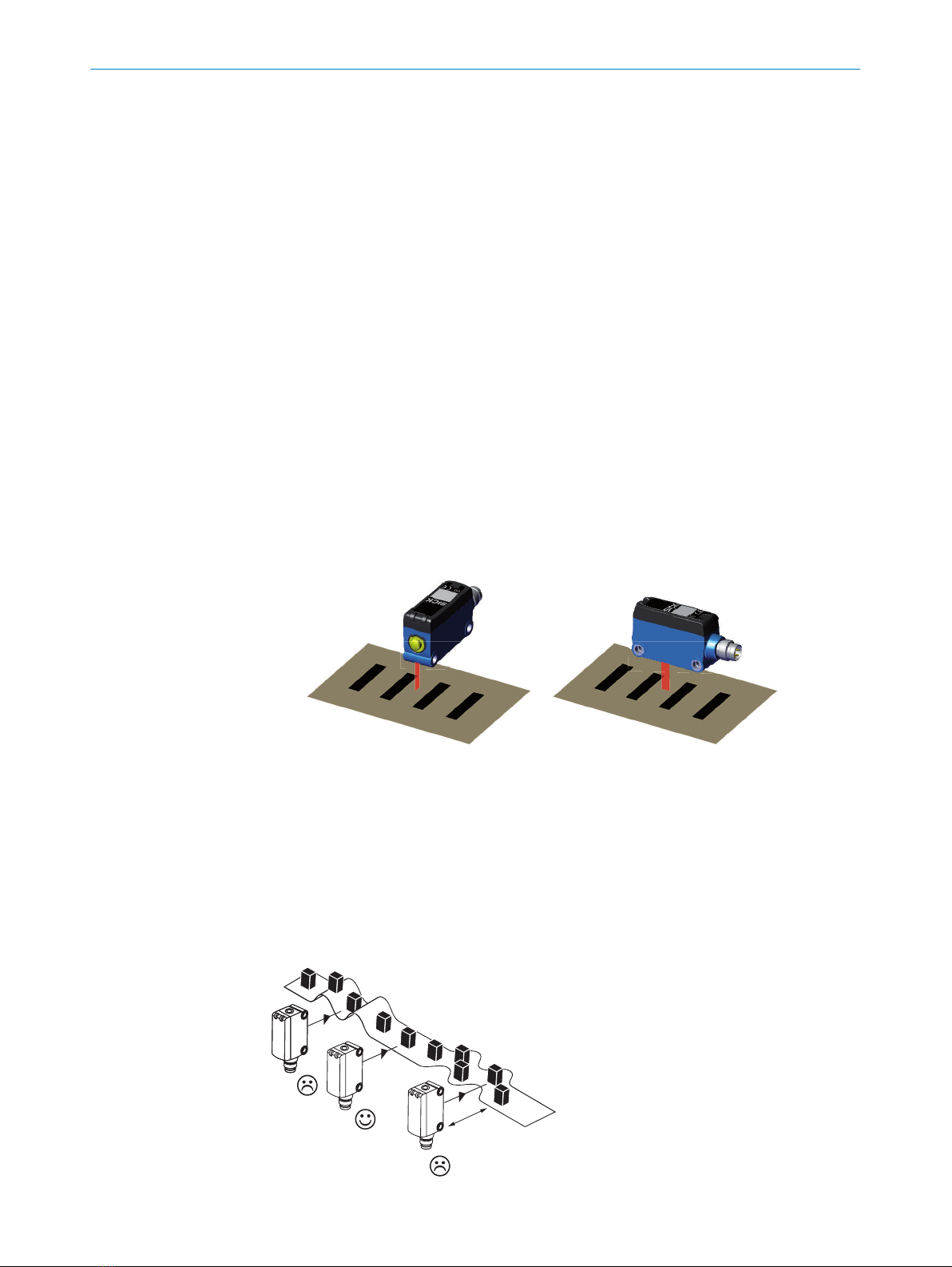
3.2 Mounting requirements............................................................................ 9
3.3 Mounting the device................................................................................. 9
4 Operating and status indicators...................................................... 11
5 Electrical installation........................................................................ 12
5.1 Notes on the electrical installation.......................................................... 12
5.2 Pin assignment of the connections......................................................... 13
5.3 Connecting the supply voltage................................................................. 13
5.4 Notes on UL approval............................................................................... 13
6 Commissioning.................................................................................. 14
6.1 Sensitivity.................................................................................................. 14
6.2 2-point-teach-in (static) via teach-in button............................................ 15
6.3 Dynamic teach-in...................................................................................... 16
7 Troubleshooting................................................................................. 18
7.1 Possible errors.......................................................................................... 18
8 Maintenance...................................................................................... 19
8.1 Maintenance............................................................................................. 19
8.2 Cleaning the device.................................................................................. 19
9 Disassembly and disposal............................................................... 21
10 Technical data.................................................................................... 22
10.1 General data............................................................................................. 22
10.2 Dimensional drawing................................................................................ 23
11 Recommended accessories............................................................ 24
12 Annex.................................................................................................. 25
12.1 Conformities and certificates................................................................... 25
CONTENTS
8025181.1EEN/06.02.2023 | SICK O P E R A T I N G I N S T R U C T I O N | KTML 3
Subject to change without notice

1 About this document
1.1 Information on the operating instructions
Read these operating instructions carefully to familiarize yourself with the product and
its functions before commencing any work.
The operating instructions are an integral part of the product and should remain acces‐
sible to the personnel at all times. If the product is passed on to a third party, these
operating instructions should be handed over with it.
These operating instructions do not provide information on the handling and safe
operation of the machine or system in which the product is integrated. Information on
this can be found in the operating instructions for the machine or system.
1.2 Further information
You can find the product page with further information under the
pid.sick.com/{P/N}/{S/N}.
{P/N} corresponds to the part number of the product, see type label or packaging.
{S/N} corresponds to the serial number of the product, see type label or packaging
(optional, if specified).
The following information is available depending on the product:
•Data sheets
•These publication in all available languages
•CAD files and dimensional drawings
•Certificates (e.g., declaration of conformity)
•Other publications
•Software
•Accessories
1.3 Symbols and document conventions
Warnings and other notes
DANGER
Indicates a situation presenting imminent danger, which will lead to death or serious
injuries if not prevented.
WARNING
Indicates a situation presenting possible danger, which may lead to death or serious
injuries if not prevented.
CAUTION
Indicates a situation presenting possible danger, which may lead to moderate or minor
injuries if not prevented.
NOTICE
Indicates a situation presenting possible danger, which may lead to property damage if
not prevented.
ABOUT THIS DOCUMENT 1
8025181.1EEN/06.02.2023 | SICK O P E R A T I N G I N S T R U C T I O N | KTML 5
Subject to change without notice

NOTE
Highlights useful tips and recommendations as well as information for efficient and
trouble-free operation.
Instructions to action
►The arrow denotes instructions to action.
1. The sequence of instructions is numbered.
2. Follow the order in which the numbered instructions are given.
✓The tick denotes the results of an action.
1 ABOUT THIS DOCUMENT
6O P E R A T I N G I N S T R U C T I O N | KTML 8025181.1EEN/06.02.2023 | SICK
Subject to change without notice

2 Safety information
2.1 Basic safety notes
Please observe the safety notes and the warnings listed here and in other sections
of this product documentation to reduce the possibility of risks to health and avoid
dangerous situations.
CAUTION
Failure to observe the relevant work safety regulations may lead to physical injury or
cause damage to the system.
Laser notes
CAUTION
Optical radiation: Laser class 1
The accessible radiation does not pose a danger when viewed directly for up to
100seconds.
Caution - if any operating or calibrating equipment other than those specified here are
used or other methods are employed, this can lead to dangerous exposure to radiation.
►Use only the operating or calibrating equipment specified in this documentation.
►Only carry out the procedures specified in this documentation.
►Do not open the housing unless carrying out the mounting and maintenance
operations provided in this documentation.
LASER
1
EN/IEC 60825-1:2014
Complies with 21CFR 1040.10 and 1040.11 except for conformance with IEC
60825-1:2007 Ed. 3., as described in Laser Notice No. 56, dated May 8, 2019.
Further laser protection regulations that need to be observed may apply (e.g. national
laws).
Mounting and electrical installation
Repairs and modifications
DANGER
Improper work on the product
A modified product may not offer the expected protection if it is integrated incorrectly.
►Apart from the procedures described in this document, do not repair, open, manip‐
ulate or otherwise modify the product.
2.2 Qualification of personnel
Any work on the product may only be carried out by personnel qualified and authorized
to do so.
SAFETY INFORMATION 2
8025181.1EEN/06.02.2023 | SICK O P E R A T I N G I N S T R U C T I O N | KTML 7
Subject to change without notice

Qualified personnel are able to perform tasks assigned to them and can independently
recognize and avoid any potential hazards. This requires, for example:
•technical training
•experience
•knowledge of the applicable regulations and standards
2.3 Intended use
The KTML contrast sensor is an opto-electronic sensor for the optical, non-contact
detection of contrasts.
A contrast sensor is designed for mounting and may only be operated according to its
intended function. For this reason, it is not equipped with direct safety devices.
The system designer must provide measures to ensure the safety of persons and
systems in accordance with the legal guidelines.
SICK AG assumes no liability for losses or damage arising from the use of the product,
either directly or indirectly. This applies in particular to use of the product that does not
conform to its intended purpose and is not described in this documentation.
UL: Only for use in application in accordance with NFPA79.
2.4 Improper use
•The device does not constitute a safety-relevant device according to the EC Machi‐
nery Directive (2006/42/EC).
•The device must not be used in explosion-hazardous areas.
•Any other use that is not described as intended use is prohibited.
•Any use of accessories not specifically approved by SICK AG is at your own risk.
The device is not suitable for the following applications (this list is not exhaustive):
•As a safety device to protect persons, their hands, or other body parts
•Underwater
•In explosion-hazardous areas
•Outdoors, without additional protection
NOTICE
Danger due to improper use!
Any improper use can result in dangerous situations.
Therefore, observe the following information:
►The device should be used only in line with intended use specifications.
►All information in these operating instructions must be strictly complied with.
2 SAFETY INFORMATION
8O P E R A T I N G I N S T R U C T I O N | KTML 8025181.1EEN/06.02.2023 | SICK
Subject to change without notice

3 Mounting
3.1 Scope of delivery
•Contrast sensor in the version ordered
•Quickstart
•Safety notes
3.2 Mounting requirements
•Typical space requirement for the device, see type-specific dimensional drawing,
see "Technical data", page 22.
•Comply with technical data, such as the permitted ambient conditions for opera‐
tion of the device (e.g., temperature range, EMC interference emissions, ground
potential).
•To prevent condensation, avoid exposing the device to rapid changes in tempera‐
ture.
•Protect the device from direct sunlight.
•The device must only be mounted using the pairs of mounting threads/fixing holes
provided for this purpose.
•Shock and vibration-free mounting.
3.3 Mounting the device
üû
Figure 1: KTML
1. Install the sensor via the fixing hole so that the light spot enters the mark
longitudinally and the test object has the least possible vertical and horizontal
movement. Note the sensing distance while doing so.
2. Compensate for the vertical and horizontal movement of the test object by marks
of suitable lengths.
3. Ensure that any sensor movement does not affect the sensing distance.
To secure a stable detection when having high gloss material a tilt angle of 10°-15°
might be necessary.
1
x
MOUNTING 3
8025181.1EEN/06.02.2023 | SICK O P E R A T I N G I N S T R U C T I O N | KTML 9
Subject to change without notice

1Distance x:
KTM-Lx22xxxx = 50 mm
KTM-Lx55xxxx = 250 mm
3 MOUNTING
10 O P E R A T I N G I N S T R U C T I O N | KTML 8025181.1EEN/06.02.2023 | SICK
Subject to change without notice

4 Operating and status indicators
1
2 3
Figure 2: Operating elements
1Yellow LED: digital output
2Green LED: Supply voltage active
3Teach-in button
NOTE
30s
Activation and deactivation: hold down teach-in button > 30s.
Yellow LED will blink continuously when holding down teach-in button during the 30sec‐
onds and off when lock is activated. When locked, the yellow indicator will not lit even
when teach-in button is pressed. To unlock, press teach in button for 30seconds.
OPERATING AND STATUS INDICATORS 4
8025181.1EEN/06.02.2023 | SICK O P E R A T I N G I N S T R U C T I O N | KTML 11
Subject to change without notice

5 Electrical installation
5.1 Notes on the electrical installation
NOTICE
Device damage due to incorrect supply voltage!
An incorrect supply voltage may result in damage to the device.
■Only operate the device with safety/protective extra-low voltage (SELV/PELV).
■The sensor is a device of protection class III.
NOTICE
Device damage due to incorrect supply voltage!
An incorrect supply voltage may result in damage to the device.
•Only operate the device with an LPS (limited power source) in accordance with IEC
62368-1 or an NEC Class 2 power supply unit.
NOTICE
Device damage or unpredictable operation due to working with live parts!
Working with live parts may result in unpredictable operation.
■Only carry out wiring work when the power is off.
■Only connect and disconnect electrical connections when the power is off.
■The electrical installation must only be performed by electrically qualified person‐
nel.
■Standard safety requirements must be met when working on electrical systems!
■Only switch on the supply voltage for the device when the connection tasks have
been completed and the wiring has been thoroughly checked.
■When using extension cables with open ends, ensure that bare wire ends do not
come into contact with each other (risk of short-circuit when supply voltage is
switched on!). Wires must be appropriately insulated from each other.
■Wire cross-sections in the supply cable from the user’s power system must be
selected in accordance with the applicable standards.
■Only operate the device with an LPS (limited power source) in accordance with IEC
62368-1 or an NEC Class 2 power supply unit.
■All circuits connected to the device must be designed as SELV/PELV circuits.
The IP enclosure rating for the device is only achieved under the following conditions:
■The cables plugged into the connections are screwed tight.
If these instructions are not complied with, the IP enclosure rating for the device is not
guaranteed!
5 ELECTRICAL INSTALLATION
12 O P E R A T I N G I N S T R U C T I O N | KTML 8025181.1EEN/06.02.2023 | SICK
Subject to change without notice

5.2 Pin assignment of the connections
Overview of pin assignment
Table 1: DC
KTM- Lxxx181P
Lxxx182P
Lxxx7A1P
Lxxx742P
1 = BN + (L+) + (L+)
2 = WH ET Q
3 = BU - (M) - (M)
4 = BK Q C/Q
4
3
2
1
4
3
2
1
Legend
L+ = supply voltage
ET = external teach-in
M = ground
Q = switching output
C = Communication
5.3 Connecting the supply voltage
NOTICE
Risk of damage to the device!
The device can become damaged if it is connected to a voltage supply that is already
switched on.
•Only connect the device when the supply cable is de-energized.
The device must be connected to a power supply unit with the following properties:
•Supply voltage DC 10,8V –28,8V (SELV/PELV as per currently valid standards)
•Electricity source with at least 4W power
To ensure protection against short-circuits/overload in the customer’s supply cables,
the wire cross-sections used must be appropriately selected and protected.
5.4 Notes on UL approval
Input voltage: 10...30 V DC (Class 2)
Input current: max. 100 mA
Output voltage: max. 30 V DC (Class 2)
Output current: max. 100 mA
Enclosure Type 1
ELECTRICAL INSTALLATION 5
8025181.1EEN/06.02.2023 | SICK O P E R A T I N G I N S T R U C T I O N | KTML 13
Subject to change without notice

6 Commissioning
6.1 Sensitivity
Light spot dimensions
Sensor
Ø 2.2
(0.09)
Ø 1.7
(0.07)
Ø 1.1
(0.04)
20
(0.79)
50
(1.97)
80
(3.15)
Figure 3: Line spot dimensions in mm (inch), 50 mm version
Ø 1.2
(0.05)
Ø 1.8
(0.07)
Ø 2.4
(0.09)
220
(8.66)
250
(9.84)
280
(11.02)
Sensor
Figure 4: Line spot dimensions in mm (inch), 250 mm version
Please note the differences in the sensitivity at different sensing ranges.
140
120
100
80
60
40
20
20
(0.79)
30
(1.18)
40
(1.57)
50
(1.97)
60
(2.36)
70
(2.76)
80
(3.15)
90
(3.54)
0
0
Sensing distance in mm (inch)
Relative sensitivity in %
Figure 5: KTML 50 mm version
140
120
100
80
60
40
20
210
(8.27)
220
(8.66)
230
(9.06)
240
(9.45)
250
(9.84)
260
(10.24)
270
(10.63)
280
(11.02)
0
Sensing distance in mm (inch)
Relative sensitivity in %
Figure 6: KTML 250 mm version
6 COMMISSIONING
14 O P E R A T I N G I N S T R U C T I O N | KTML 8025181.1EEN/06.02.2023 | SICK
Subject to change without notice

6.2 2-point-teach-in (static) via teach-in button
1. Bring the mark into the light spot and start teach-in with teach-in pushbutton (> 1
s ≤ 3 s).
> 1 s ≤ 3 s
The emitted light and the yellow LED flash slowly: i. e. second teach-in process
must be triggered.
2. Bring background into the light spot and start teach-in with teach-in button (> 20
ms < 3 s).
< 3 s
✓The optimum emitted light is automatically selected. The switching threshold is set
in the center between the mark’s receive signal and background and is stored in a
nonvolatile memory. Output active by mark (first teach-in).
This example is showing dark switching (switch on the mark):
NOTE
Light / dark switch:
The light/dark setting is defined using teach-in sequence.
Light switch can be achieved by teaching the background first and then the mark.
COMMISSIONING 6
8025181.1EEN/06.02.2023 | SICK O P E R A T I N G I N S T R U C T I O N | KTML 15
Subject to change without notice

6.3 Dynamic teach-in
Dynamic teach-in via teach-in button
1. Bring the mark or background into the light spot. Hold down teach-in button > 3 s
< 30 s.
> 3 s ≤ 30 s
The emitted light and the yellow LED flash slowly. Move material through light spot
(min. one repeat length).
✓Quit the teach-in procedure by releasing the teach-in-button. The optimum emitted
light is automatically selected.
The switching threshold is set in the center between the mark‘s receive signal
and background and is stored in a nonvolatile memory. Output will be activated by
mark (first teach-in).
Dynamic teach-in via ET
Dynamic teach-in can also be done via the control cable. Control cable High > 30 ms.
Connecting pin 2 (ET) to pin 1 +(L+).
6 COMMISSIONING
16 O P E R A T I N G I N S T R U C T I O N | KTML 8025181.1EEN/06.02.2023 | SICK
Subject to change without notice

Switching threshold ‘’close to mark’’ via teach-in-button
NOTE
By default, the switching threshold is set in the center between the background and the
mark. In the event of intermittent error switching on the background, it may be helpful
to place the threshold close to the mark to increase stability (dotted line instead of solid
line in the figure below).
1
2
3
1Switching output Q
2Switching threshold
3Internal signal received
This can be done by pressing teach-in button again > 20 ms and < 10 s after static or
dynamic teach-in. Emitted light and function LED flash 2 x. If the switching threshold is
to be reset to the center, new teach-in is required.
NOTE
Light / dark switch:
Switching output active on mark, if background is longer in the field of view during the
teach-in or vice versa.
This can be reversed if mark is longer in the field of view during the teach in process.
COMMISSIONING 6
8025181.1EEN/06.02.2023 | SICK O P E R A T I N G I N S T R U C T I O N | KTML 17
Subject to change without notice

7 Troubleshooting
7.1 Possible errors
Table 2: Troubleshooting
Display, error situation Cause Measure
•Function LEDs blinking
•Q Emitted light blinking
•5 Hz pulse via switching
output Q
•Insufficient contrast
•Sensing distance
exceeded
•Readjust sensor
•Clean the sensor lens
•Try tilting the sensor
7 TROUBLESHOOTING
18 O P E R A T I N G I N S T R U C T I O N | KTML 8025181.1EEN/06.02.2023 | SICK
Subject to change without notice

8 Maintenance
8.1 Maintenance
During operation, the device works maintenance-free.
Depending on the assignment location, the following preventive maintenance tasks
may be required for the device at regular intervals:
Table 3: Maintenance schedule
Maintenance work Interval Implementation
Clean housing and front screen Cleaning interval depends on ambi‐
ent conditions and climate
Specialist
Check screw connections and plug
connectors
Every 6 months Specialist
8.2 Cleaning the device
At regular intervals (e.g., weekly), check the light emission window and the housing of
the device for dirt. This is especially relevant in harsh operating environments (dust,
abrasion, damp, fingerprints, etc.). The lens of the light emission window must be kept
clean and dry during operation.
NOTICE
Device damage due to improper cleaning!
Improper cleaning may result in device damage.
■Only usesuitable cleaning agents.
■Never use sharp objects for cleaning.
Cleaning the light emission window
NOTICE
Damage to the light emission window!
Reduced reading performance due to scratches or streaks on the light emission win‐
dow!
►Clean the light emission window only when wet.
►Use a mild cleaning agent that does not contain powder additives. Do not use
aggressive cleaning agents, such as acetone, etc.
►Avoid any movements that could cause scratches or abrasions on the light emis‐
sion window.
►Only use cleaning agents suitable for the lens material.
NOTE
Static charge may cause dust particles to stick to the light emission window. This effect
can be avoided by using an anti-static glass cleaner in combination with the SICK lens
cloth (can be obtained from www.sick.com).
NOTE
If the light emission window is scratched or damaged (cracked or broken), the device
must be replaced. Contact SICK Service to arrange this.
MAINTENANCE 8
8025181.1EEN/06.02.2023 | SICK O P E R A T I N G I N S T R U C T I O N | KTML 19
Subject to change without notice

Cleaning the housing
In order to ensure that the heat produced by the internal power loss is adequately
dissipated, the housing surface must be kept clean.
8 MAINTENANCE
20 O P E R A T I N G I N S T R U C T I O N | KTML 8025181.1EEN/06.02.2023 | SICK
Subject to change without notice
This manual suits for next models
7
Table of contents
Other SICK Accessories manuals

SICK
SICK CSS High Speed User manual

SICK
SICK PowerProx Mini WTT4SLC User manual

SICK
SICK WS24-2 Series User manual

SICK
SICK PowerProx WTT12L-A Series User manual

SICK
SICK SureSense HSE18 Series User manual

SICK
SICK MRS1000 User manual

SICK
SICK GSE20 User manual

SICK
SICK LFR User manual

SICK
SICK CFP CUBIC User manual

SICK
SICK LFV 200 User manual

SICK
SICK HTE18 Series User manual

SICK
SICK RSB1 1 Series User manual

SICK
SICK WTF16 User manual

SICK
SICK SureSense HSE18 Series User manual

SICK
SICK MPS-G User manual

SICK
SICK W26 User manual

SICK
SICK LMS4000 User manual

SICK
SICK SIM1004 User manual

SICK
SICK TiM4 Series User manual

SICK
SICK deTec4 Core User manual