manuals.online logo
Brands
  1. Home
  2. •
  3. Brands
  4. •
  5. Crown
  6. •
  7. Accessories
  8. •
  9. Crown IQ-MC4A User manual

Crown IQ-MC4A User manual

C T S M U L T I C H A N N E L
A M P L I F I E R A C C E S S O R I E S
IQ-MC4A
IQ-MC8
he Crown®IQ-MC4A and IQ-MC8 are
optional IQ control modules for the Crown
CTs multichannel power amplifiers. The
IQ-MC4A is the IQ module for the CTs 4200,
and the IQ-MC8 is the IQ module for the CTs
8200.
A single IQ-MC module provides IQ control
and monitoring capability to all channels of the
amplifier. Features include basic IQ amplifier
control and monitoring, including attenuation,
mute, polarity, input level, output level, power
supply temperature, and thermal level meters.
Advanced features include IOC, Thermal and
Fault error reporting, Load Supervision, output
limiting, Listen Bus, AUX control port, 10
presets, and real-time “read-only” software
indication of amplifier hardware indicator, level
control, and mode switch status.
Crown CTs 4200 and 8200 amplifiers can be
supplied with an IQ-MC module already fac-
tory-installed, or your choice of MC modules
can be easily added to the amplifier by any
authorized Crown Service Center.
For more details about the Crown IQ-MC4A
and IQ-MC8, contact Crown Technical Support
at 800-342-6939 or 574-294-8200. Also, visit
the Crown Audio website at
www.crownaudio.com. Software is at
www.iqaudiosystems.com. The IQ-MC4A or
IQ-MC8 require version 5.1.2 or higher.
Specifications
General
External Controls: An 8-segment DIP switch
sets the IQ address (decimal range: 1–250). If
address “0” is selected, the IQ-MC will operate
in stand-alone mode. In this mode, the Crown
bus port is deactivated.
A Reset/Preset switch is accessible with a
straightened paper clip through the module’s
front panel. The switch operates like this:
• Press < 2 seconds: Select the next user
preset.
• Press > 2 seconds: Reset user settings to
factory default.
• Press while applying power: Rewrite from
firmware to flash memory, restoring all settings
to factory default.
Connectors:
IQ BUS IN: RJ-45 connector.
IQ BUS OUT: RJ-45 connector for daisy-chain
output.
AUX: Aux In/Aux Out/Listen Bus on RJ-11
connector.
Indicators: A yellow DATA indicator flashes
when a valid IQ command is received from the
IQ System via the IQ Bus. The DATA indicator
can be forced on to facilitate rapid trouble-
shooting of IQ Bus wiring. A green PRESET
indicator flashes to indicate the user preset
number currently selected in memory. If the
PRESET indicator does not flash the preset
number when selected, this indicates the
preset has been modified by the user.
Memory Backup: 8 Kbyte EEPROM for backup
of run-time parameters, presets, and program
storage. Capable of 80,000 writes minimum.
IQ Bus Data CommunicationProtection: If
communication is lost, the unit will continue to
function with the last commands received.
Data Rate: 38.4 K BAUD.
Data Format: Serial, binary, asynchronous,
1 start bit, 1 stop bit, 8 data bits, no parity.
IQ Bus Interface Type: Optically isolated 20
milliamp serial loop.
Operation: Half duplex.
Transmission Distance: Variable from 200 to
3000 feet (61 to 914 m), depending upon wire
capacitance. Typically 1000 feet (305 M) using
shielded twisted-pair wire, #26 AWG or larger.
Can be extended with an IQ Repeater.
Audio
Audio specifications are referenced to 0.775 V
(0 dBu). Measurements were made at the
output of the IQ-MC module itself.
Maximum Input Level: +20 dBu.
Dynamic Range: > 100 dB (A-weighted, 20 Hz
to 20 kHz).
Frequency Response: ± 1 dB from 20 Hz to
20 kHz.
Common Mode Rejection (CMR): 50 dB
(typical).
Total Harmonic Distortion + Noise (THD+N):
< 0.05% (1 kHz, 0dBu).
Maximum Output Level: +20 dBu.
IQ System Data Acquisition: Multi-channel,
14-bit Analog to Digital Converter.
Basic IQ amplifier control and
monitoring, including:
• Attenuation
• Mute
• Polarity
• Input level
• Output level
• Power supply temperature
• Thermal level meters
Advanced Features
• IOC error reporting
• Thermal and Fault error reporting
• Load Supervision error reporting
• Output limiting
• Listen Bus
• AUX control port
• 10 presets
• Real-time “read-only” software indi
cation of amplifier hardware indicator,
level control, and mode switch status
• Error reporting for level control or
mode switch position change
Features
IQ-MC8
Crown International, Inc.
P.O. Box 1000
Elkhart, IN 46515-1000
TEL: 574-294-8000
FAX: 574-294-8FAX
www.crownaudio.com
www.iqaudiosystems.com
Specifications subject to change without prior
notice. Latest information available at
www.crownaudo.com.
Crown and Crown Audio are registered trade-
marks of Crown International. Other trademarks
are the property of their respective owners.
Printed in U.S.A.
5/04 135426-1A
IQ-MC4A
IQ-MC8
Crown’s Three-Year, No-Fault, Fully Transferable Warranty
Crown offers a Three-Year, No-Fault, Fully Transferable Warranty for every new Crown amplifier
product—an unsurpassed industry standard. With this unprecedented No-Fault protection, your
new Crown amplifier product is warranted to meet or exceed original specifications for the first
three years of ownership. During this time, if your unit fails, or does not perform to original
specifications, it will be repaired or replaced at our expense. About the only things not covered
by this warranty are those losses normally covered by insurance and those caused by intentional
abuse. And the coverage is transferable, should you sell your unit.
See your authorized Crown dealer for full warranty disclosure and details. For customers outside
of the USA, please contact your authorized Crown distributor for warranty information or call
574-294-8200.
Figure 1. Sample screen capture of IQ software used with IQ-MC4A and IQ-MC8
IQ-MC4A

This manual suits for next models

1

Other Crown Accessories manuals

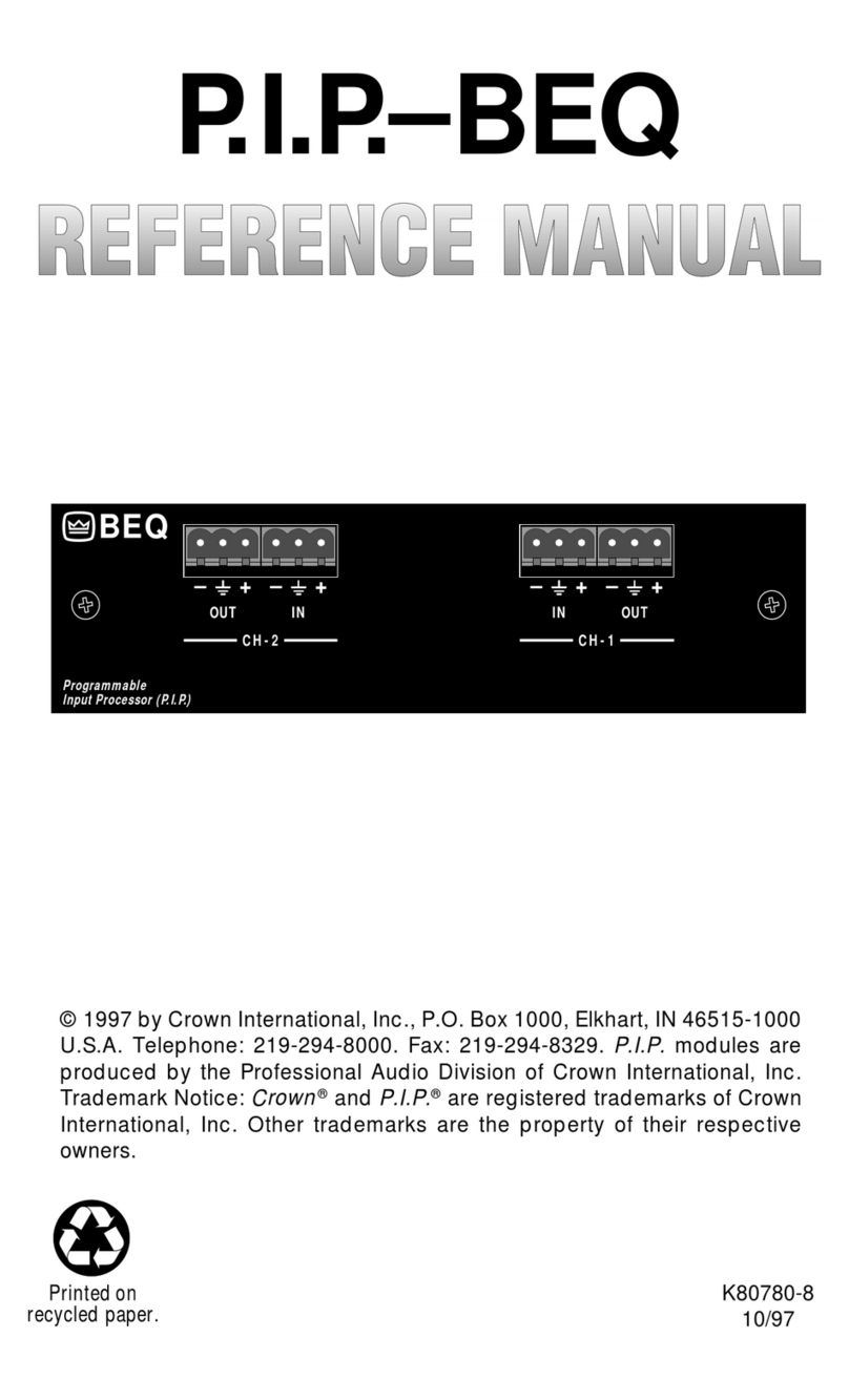
Crown PIP-BEQ User manual

Crown

Crown PIP-BEQ User manual

Crown PIP-ATNB User manual

Crown

Crown PIP-ATNB User manual

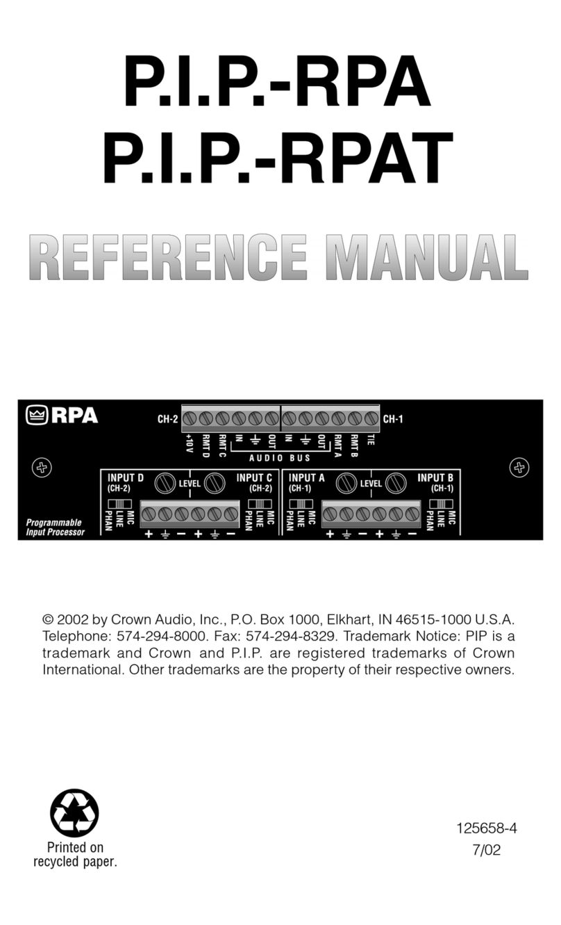
Crown PIP-RPA User manual

Crown

Crown PIP-RPA User manual

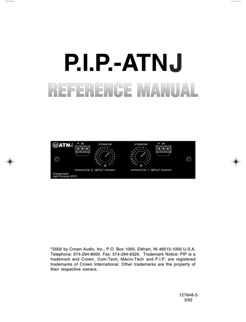
Crown PIP-ATNJ User manual

Crown

Crown PIP-ATNJ User manual

Crown IQ-MC4 User manual

Crown

Crown IQ-MC4 User manual

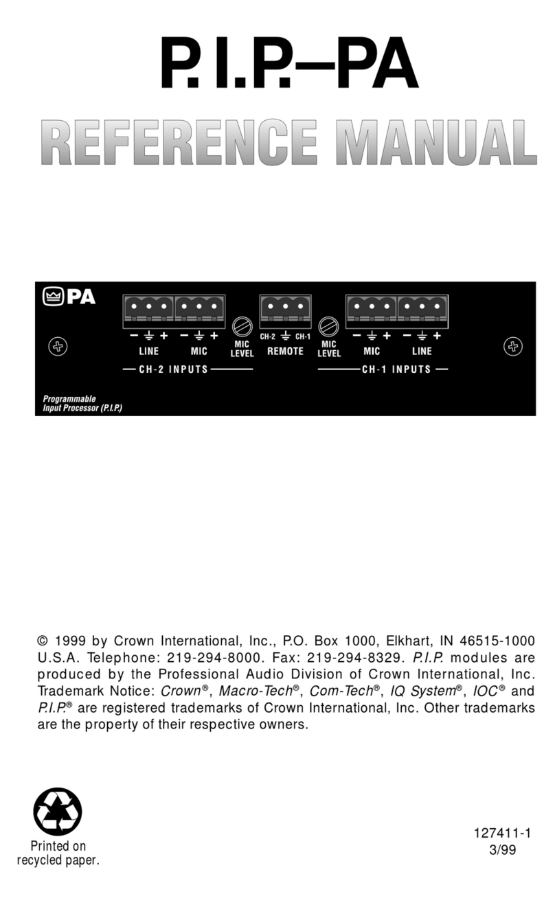
Crown PIP-PA User manual

Crown

Crown PIP-PA User manual

Crown PIP-FMX User manual

Crown

Crown PIP-FMX User manual

Crown PIP-FTE User manual

Crown

Crown PIP-FTE User manual

Crown PIP-AMCB User manual

Crown

Crown PIP-AMCB User manual

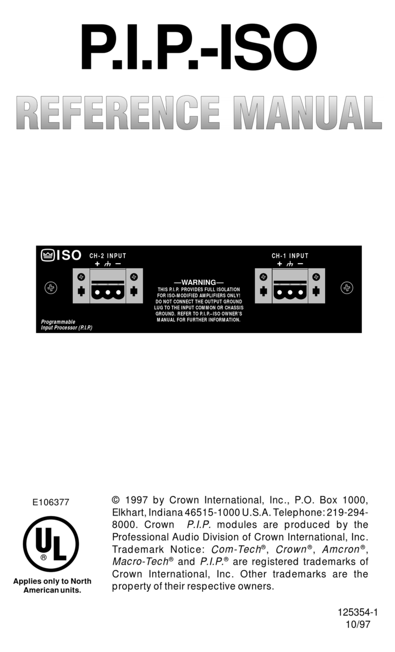
Crown PIP-ISO User manual

Crown

Crown PIP-ISO User manual

Crown MB-100 User manual

Crown

Crown MB-100 User manual

Crown PIP-AMC User manual

Crown

Crown PIP-AMC User manual

Crown PIP-CLP User manual

Crown

Crown PIP-CLP User manual

Crown Studio Reference II User manual

Crown

Crown Studio Reference II User manual

Crown MT-XLR User manual

Crown

Crown MT-XLR User manual

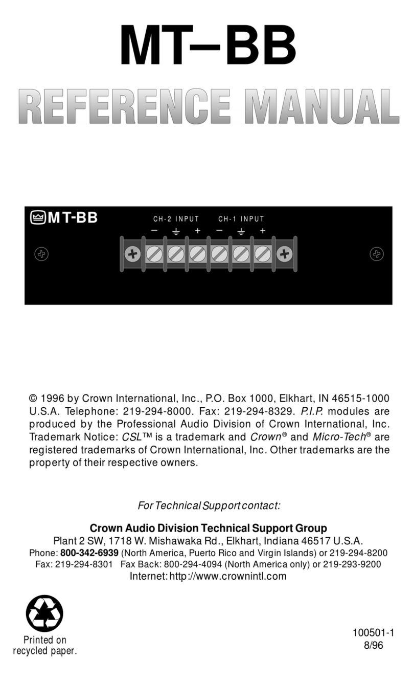
Crown MT-BB User manual

Crown

Crown MT-BB User manual

Popular Accessories manuals by other brands

PROAIM CINEMA P-BMLS-01 Assembly manual

PROAIM

PROAIM CINEMA P-BMLS-01 Assembly manual

Superfly SUPERX8 user manual

Superfly

Superfly SUPERX8 user manual

Turner Cyclops 6K user manual

Turner

Turner Cyclops 6K user manual

BENDIX Smartwave LF Tool user manual

BENDIX

BENDIX Smartwave LF Tool user manual

Tascam FW-1082 Application guide

Tascam

Tascam FW-1082 Application guide

Rechner Sensors SmartPaddle Series instruction manual

Rechner Sensors

Rechner Sensors SmartPaddle Series instruction manual

Monnit PoE X user guide

Monnit

Monnit PoE X user guide

Renogy SNZB-04 manual

Renogy

Renogy SNZB-04 manual

Zoom R24 user manual

Zoom

Zoom R24 user manual

Kaipule IX30-Z-Wave user guide

Kaipule

Kaipule IX30-Z-Wave user guide

daviteq WSSFC-G4F-NH3-8-01 user guide

daviteq

daviteq WSSFC-G4F-NH3-8-01 user guide

Petra electric AS 10 Instructions for use

Petra electric

Petra electric AS 10 Instructions for use

Kobold NGR operating instructions

Kobold

Kobold NGR operating instructions

Cameron AMZ30DB quick start guide

Cameron

Cameron AMZ30DB quick start guide

CAS CI-2001AS owner's manual

CAS

CAS CI-2001AS owner's manual

Lippert Components SURESHADE ATF Installation instructions and owner's manual

Lippert Components

Lippert Components SURESHADE ATF Installation instructions and owner's manual

Bamo MAXIMAT LW C Series instruction manual

Bamo

Bamo MAXIMAT LW C Series instruction manual

Novalynx 200-WS-23-DP user manual

Novalynx

Novalynx 200-WS-23-DP user manual

manuals.online logo
manuals.online logoBrands
  • About & Mission
  • Contact us
  • Privacy Policy
  • Terms and Conditions

Copyright 2025 Manuals.Online. All Rights Reserved.