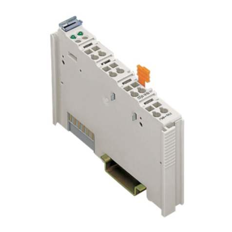
Eelectron BI04F01KNX User manual

USER MANUAL
Translation of the original instructions
Version: 1.0
Date: 18/07/2023
BI04F01KNX Universal DIN Module 4 Digital Inputs
BI08F01KNX Universal DIN Module 8 Digital Inputs

BI0xF01KNX
2BI0xF01KNXFI00020100_UM_EN_1.0
MEMBER
Index
1. Introduction to the user manual ................................................................................................................................................4
Meaning of the symbols used ................................................................................................................................................. 4
2. Product overview ......................................................................................................................................................................4
3. Installation instructions ..............................................................................................................................................................4
4. Congurationandcommissioning.............................................................................................................................................5
5. General parameters ..................................................................................................................................................................5
General settings...................................................................................................................................................................... 5
InputsConguration................................................................................................................................................................ 6
6. Digital Input ...............................................................................................................................................................................6
7. Logics ........................................................................................................................................................................................6
8. CO2 and VOC sensor ...............................................................................................................................................................6
9. Behaviour on bus failure, recovery and download ................................................................................................................... 6
Behaviour on bus voltage failure ............................................................................................................................................ 6
Behaviour on bus voltage recovery ........................................................................................................................................ 6
Wrong application download................................................................................................................................................... 6
VERSION DATE CHANGES
1.0 18/07/2023 -

BI0xF01KNX
3BI0xF01KNXFI00020100_UM_EN_1.0
MEMBER
Any information inside this manual can be changed without ad-
vice.
This handbook can be download freely from the website:
www.eelectron.com
Exclusion of liability:
Despite checking that the contents of this document match the
hardware and software, deviations cannot be completely exclu-
ded. We therefore cannot accept any liability for this.
Any necessary corrections will be incorporated into newer ver-
sions of this manual.
Eelectron S.p.A.
Via Claudio Monteverdi 6, I-20025 Legnano (MI), Italia

BI0xF01KNX
4BI0xF01KNXFI00020100_UM_EN_1.0
MEMBER
1. Introduction to the user manual
This manual is intended for use by KNX installers and describes
functions and parameters of the BI04F01KNX and BI08F01KNX
devicesandhowthesettingsandcongurationscanbechanged
using the ETS software tool.
For the technical data of the device and the compatible accesso-
ries, please refer to the datasheet of the device itself.
Meaning of the symbols used
WARNING - The operation or phase described must be
carried out in compliance with the instructions provided
and with the safety standards.
IMPORTANT NOTE - Detailsandspecicationstobere-
spected for the correct functioning of the device.
2. Product overview
The BI04F01KNX and BI08F01KNX devices are equipped
with 4(8) inputs for interfacing dry contacts, for example sen-
sors,switchbuttonsandcanbeconguredforsendingon/o
commands, dimmers, roller shutters, scene recall and sequen-
ces to the bus.
Thedigitalinputscanbecongured for long or short distan-
ces.
The lines (long distance) can be monitored using an end of
line resistor (EOL) of1.8KΩ[1/8W]valuewhichallowsthede-
vice to manage sensors with a higher level of safety such as
magnetic contacts, motion detectors.
The pulse counter function is also available for counting the
switching on inputs congured as digital at short distance. On
the front panel there is a LED to display the status of each input.
Theinputs(forBI08F01KNXonlyinputs1,3,5,7)canbecon-
gured as analogue for the connection of NTC temperature pro-
bes(seeeelectronprobescodeTS01A01ACC/TS01B01ACC
/TS01D01ACC) withwhich tosend thetemperature measure-
ment on the bus or manage a complete thermostat module. The
thermostat manages 2 stages with an integrated PI controller for
controlling heating and cooling equipment, valves, 2 and 4-pipe
fan coils, etc.
Twoinputscanbeconguredas“smart sensor” for connection
of the plug-in sensors: SM03E01ACC that includes a di tempera-
ture sensor (range from -5°C to +50°C) and a CO2 sensor (range
from 10 ppm to 1000 ppm) and SM03E02ACC that includes a
temperature sensor (range from -5°C to +50°C) and a VOC sen-
sor for measuring Indoor Air Quality (IAQ) and CO2 equivalent
(eCO2).
Moreover, 10 logic blocks are available to implement sim-
ple expressions with logical or threshold operator or complex
expressions with algebraic and conditional operators; It is possi-
bletousepredenedalgorithmsasproportionalcontrolsoftem-
perature and humidity or dew point calculation.
Device is equipped with KNX communication interface and is in-
tended for installation on DIN rail in LV distribution switchboards.
3. Installation instructions
The device can be used for permanent internal installations in
dry places.
WARNING
• When a clear separation between the low voltage (SELV)
and the dangerous voltage (230V) is NOT possible, the de-
vice must be installed maintaining a minimum guaranteed
distance of 4 mm between the dangerous voltage lines or
cables (230V not SELV) and the cables connected to the
EIB/KNXBUS(SELV).
• The device must be mounted and commissioned by an au-
thorized installer.
• The applicable safety and accident prevention regulations
must be observed.
• The device must not be opened. Any faulty devices should
be returned to manufacturer.
• For planning and construction of electric installations, the re-
levant guidelines, regulations and standards of the respecti-
ve country are to be considered.
• KNX bus allows you to remotely send commands to the
system actuators. Always make sure that the execution of
remote commands do not lead to hazardous situations, and
that the user always has a warning about which commands
can be activated remotely.
For more information: www.eelectron.com.

BI0xF01KNX
5BI0xF01KNXFI00020100_UM_EN_1.0
MEMBER
4. Conguration and commissioning
Thecongurationandcommissioningofthedeviceismadewith
theETS®(EngineeringToolSoftware).Forthecongurationof
the device parameters the corresponding application program or
the whole eelectron® product database must be loaded in the
ETS® program.
The commissioning of the device requires the following steps:
• connect the bus KNX (1)
• turn on the bus power supply
• press the programming button (2); the red programming
LED turns ON
• download into the device the physical address and the con-
gurationwiththeETS®program
5. General parameters
In ETS®, in the drop down menu of the device the general pa-
rameters consist of two conguration blocks, described in the
next paragraphs.
General settings
Communication objects involved:
“<General> Heartbeat” 1 Bit CRT
“<Global> Enable” 1 Bit CW
KNX PARAMETER SETTINGS
Delay on power-up 3 ÷ 15 seconds
Through this parameter it is possible to set the telegram transmission
delay after switch-on by selecting the time beyond which the device is
authorized to send telegrams.
In large systems, after a power outage or shutdown, this delay avoids
generatingexcessivetraconthebuswhichcauseslowperformance
or a transmission crash.
In case of several devices requiring telegrams to be sent on the bus
afterareset,thesedelaysmustbeprogrammedtopreventtraccon-
gestion during the initialization phase.
Input detection and object values are updated at the end of the trans-
mission delay time
At the end of ETS programming, the device behaves as it did after it
was switched on.
Heartbeat
(periodic alive notication)
nothing
periodic
on request
The parameter allows you to notify a hierarchically superior control
orsupervision systemofyourexistence/correctonlineactivity.The
noticationcantakeplacespontaneously(periodically-settableperi-
od value) or following a query (upon request). The value of the 1-bit
noticationtelegramcanbeset.
Telegram value o/on/toggle
Denesthevalueofthe1bitnoticationtelegram.Thetogglevalueis
notavailablefor“ondemand”conguration.
Period - time unit seconds/minutes/hours
Denestheunitofmeasureofthenoticationtimeinterval.Thispa-
rameterisnotavailableforthe“ondemand”conguration.
Period - time value 1 ... 255
Denesthe noticationintervaltime.This parameterisnotavailable
forthe“ondemand”conguration.
Global enable object disabled/enabled
Use this parameter to activate object “<Global> Enable”: through
this object it is possible to enable or disable all the inputs at the
same time with a single command, saving commands and bus
engagement.
Global enable state after down-
load
disabled/enabled
Itdenesthestatusoftheobject“<Global>Enable”afterdownload.
Global enable activation tele-
gram
telegram“0”/telegram“1”
Itdenesthetelegramofactivationoftheobject“<Global>Enable”.
Economy mode: switch OFF
leds after download
neverswitcho
1 ... 15 minutes
- KNX +
IN1 IN2 CIN3 IN4 C IN5 IN6 CIN7 IN8 C
BI08F
1
2

BI0xF01KNX
6BI0xF01KNXFI00020100_UM_EN_1.0
MEMBER
Through this parameter it is possible to save energy by establishing
whether the status LEDs relating to the inputs must show their con-
dition constantly (for example if the input has received an activation
command, stay on) or if they should go o after a certain time has
elapsed from the last activation.
Never switch OFF
The LED associated with each input remains lit as long as the active
input condition determined by the settings in the ETS page of each
input continues.
Economy mode
ThestatusLEDlightsupwhentheinputisactivatedandturnsoaf-
ter the lesser of the active condition maintaining time and the interval
dened(1...15minutes).
Inputs Conguration
Forboththedevices,theinputscanbeconguredasinthefol-
lowing table:
Input
BI08
Input
BI04
Long
Distance
Short
Distance Analog CO2 /
VOC
1 1 X X X X
2 X X - -
3 2 X X X X
4 X X - -
5 3 X X X -
6 X X - -
7 4 X X X -
8 X X - -
KNX PARAMETER SETTINGS
Input X
Long distance digital (high cur-
rent)
Short distance digital (low current)
Temperature function (analog)
CO2/VOCsensor(analog)
Long distance digital (high current)
≤100m-itcanbeconguredasstandardinputorasanEOLresistor;
this mode is used to insert a terminating resistor of the input line in
order to detect the interruption of the cables due to accidents or ma-
licious cutting.
Short distance digital (low current)
≤30m-itisconguredonlyasstandardinput;itispossibletoactivate
function “counter input”.
Temperature function (analog)
ItcanbeconguredasanalogfortheconnectionofNTCtemperature
probes (see eelectron probes code TS01A01ACC /TS01B01ACC /
TS01D01ACC) with which to send the temperature measurement on
the bus or manage a complete thermostat module.
CO2/VOC sensor (analog)
It can be congured as “smart sensor” for connection of the plug-in
sensors: SM03E01ACC that includes a di temperature sensor (range
from -5°C to +50°C) and a CO2 sensor (range from 10 ppm to 1000
ppm) and SM03E02ACC that includes a temperature sensor (range
from -5°C to +50°C) and a VOC sensor for measuring Indoor Air Qual-
ity (IAQ) and CO2 equivalent (eCO2).
6. Digital Input
Please refer to the “Digital Input” user manual.
7. Logics
Please refer to the “Logics” user manual.
Each logic block can be congured to perform one of the
following functions available in the drop-down menu on the
corresponding page:
• bit no transfer function;
• byte no transfer function;
• NOT, AND, OR, NAND, NOR, XOR, XNOR;
• bit to byte conversion;
• byte to bit conversion;
• byte threshold;
• 2 bytes oat threshold;
• 4 bytes oat threshold;
• proportional fancoil;
• proportional / speed fancoil conversion;
• dew point humidistat;
• surveillance;
• constant illuminance;
• expression
In the devices described, the logical expression can
have a maximum of 16 characters.
8. CO2 and VOC sensor
Please refer to the “CO2/VOC” user manual.
9. Behaviour on bus failure, recovery and
download
Behaviour on bus voltage failure
On failure of bus voltage, no command is sent. Behaviour of con-
trolled actuators must be set using their own parameters.
Behaviour on bus voltage recovery
On bus voltage recovery all the communication objects are set
to0exceptforobjectsforwhichaparameterisdenedforthe
initial value.
Wrong application download
If the wrong ETS application is downloaded then KNX/EIB led
starts blinking and device is not operative on the bus. A power re-
set must be done or the correct ETS application must be downlo-
aded.
This manual suits for next models
1
Table of contents
Other Eelectron I/O System manuals
Popular I/O System manuals by other brands

Vantage Hearth
Vantage Hearth STIDEW101 Installation

VERTICALLY URBAN
VERTICALLY URBAN VU-POWERDRIVE manual

Rockwell Automation
Rockwell Automation Allen-Bradley C Series installation instructions

turck
turck TBPN-L FDIO1-2IOL Series user manual

NI
NI CB-2162 user guide

Siemens
Siemens SIMATIC ET 200eco manual

Allen-Bradley
Allen-Bradley SLC 500 1747-L511 Installation and operation manual

Homematic IP
Homematic IP HmIPW-DRI32 Installation instructions and operating manual

WAGO
WAGO WAGO-I/O-SYSTEM750 Series manual

Omron
Omron GRT1-ECT SmartSlice Operation manual

M-system
M-system R7C-CT4E instruction manual

Emerson
Emerson I/O MODULE IPMC7126E Installation and use


