EF Johnson Technologies 3800 series User manual

October 2009 3800 Digital Repeater Operating Manual 1 -1
Section
1
Section 13800 Information
1.1 General Description
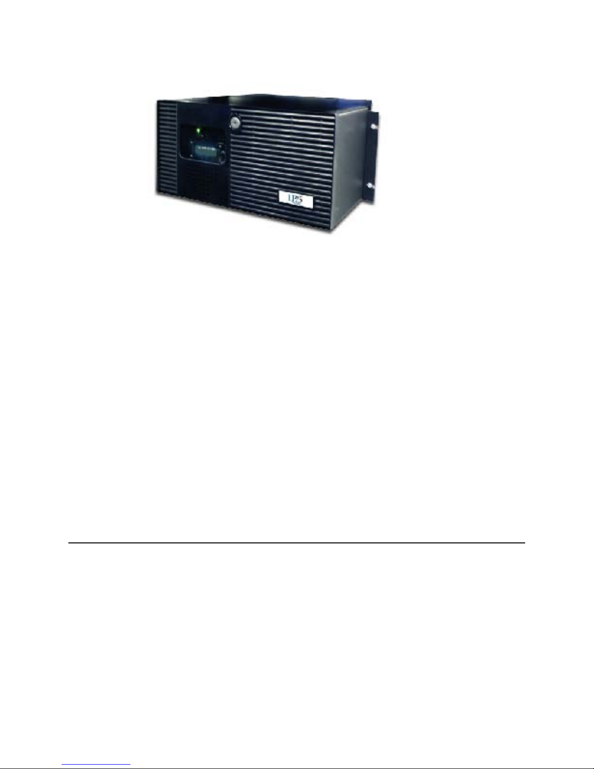
The EF Johnson Technologies 3800 Series Digital Repeaters are designed specifically for radio trunking
operations. The 3800 integrates the functions of radio repeater and trunking channel controller into one
unit. See Figure 1.1.
Figure 1.1 3800 Series Digital Repeater
3800 Information
1 -2 3800 Digital Repeater Operating Manual October 2009
The radio
component provides a transmitter and receiver with software programmable frequency and power
selection. Transmitter and receiver signals are encoded and sampled by dual Digital Signal Processors
DSP).
Channel controllers in each repeater manage the control and traffic channels for frequency assignments
and transmitter power level. The local site controller is integrated into one of the repeaters. The Trunked
IP25 System supports the ability to have backup site controllers, but only one site controller is required
per site.
Multiple repeaters may be used per site to accommodate multiple frequencies, traffic level, and provide
radio channel backup. One repeater is required for a control channel and one or more repeaters for traffic
channels.
A built-in ethernet interface lets the repeater communicate over the Trunked IP25 System IP network to
other system components.
1.1.1 Models & Features
The 3800 Series Repeater consists of various models and features. Please refer to the 3800 Digital
Repeater Service Manual for descriptions of the different models, identification and part number
information.
3800 Information
October 2009 3800 Digital Repeater Operating Manual 1 -3
1.2 Functional Description
The EF Johnson Technologies 3800 Series Digital Repeater is a trunked repeater with built-in trunking
control. The Trunked IP25 System Channel Controller function is integrated into the repeater subsystem.
The 3800 Repeater uses frequency synthesizer and Digital Signal Processor (DSP) technologies to
provide digital control of the radio channels. Software defined configurations allow for quick updates and
programmable operating frequency, output power, and other key functions.
Multiple repeaters may be used per site to accommodate multiple frequency bands and provide radio
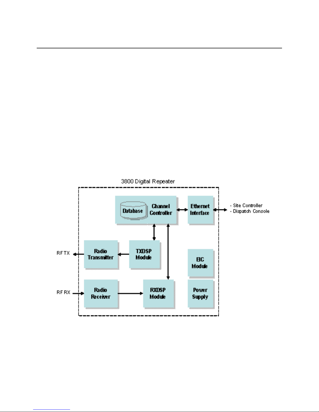
backup. The 3800 is comprised of the following functional modules
( Figure 1.2):
Figure 1.2 3800 Repeater Subsystem Functional Diagram
Channel Controller
All channels are managed by the integrated Channel Controller. The controller provides overall channel
control for control and traffic channels in a repeater. It manages the radio transmitter and receiver
frequency assignments and power levels. The Channel Controller checks channel status and reports any

3800 Information
1 -4 3800 Digital Repeater Operating Manual October 2009
channel failures or processing errors to the Site Controller. One Channel Controller is used for each radio
repeater subsystem (in multiple repeater systems).
TXDSP Module
The TXDSP module manages the repeater radio transmitter interface. This module provides channel
encoding with forward error detection and correction coding. It receives data packets from the channel
controller and creates a signal for the transmitter.
Radio Transmitter
The Radio Transmitter is digital synthesizer based to ensure on-frequency and high stability operation. It
converts the processed signal from the TXDSP module into a radio frequency (RF) signal for
transmission.
Radio Receiver
The Radio Receiver is digital synthesizer based to ensure on-frequency and high stability operation. It
receives and converts the radio frequency signals for processing by the RXDSP module.
RXDSP Module
The RXDSP module manages the repeater radio receiver interface. It processes the received signal
samples from the radio receiver into data packets. The module then sends the data packets to the Channel
Controller.
Ethernet Interface
The repeater communicates over its Ethernet interface with the Site Controller, Dispatch Console, and
Network Management System (NMS).
EIC Module
The EIC module provides a user interface to the repeater including a 2-line display and push button rotary
knob for menu navigation.

3800 Information
October 2009 3800 Digital Repeater Operating Manual 1 -5
Power Supply
The power supply accepts the AC line power input and converts it into the various DC power
requirements of the repeater.
1.3 System Configuration
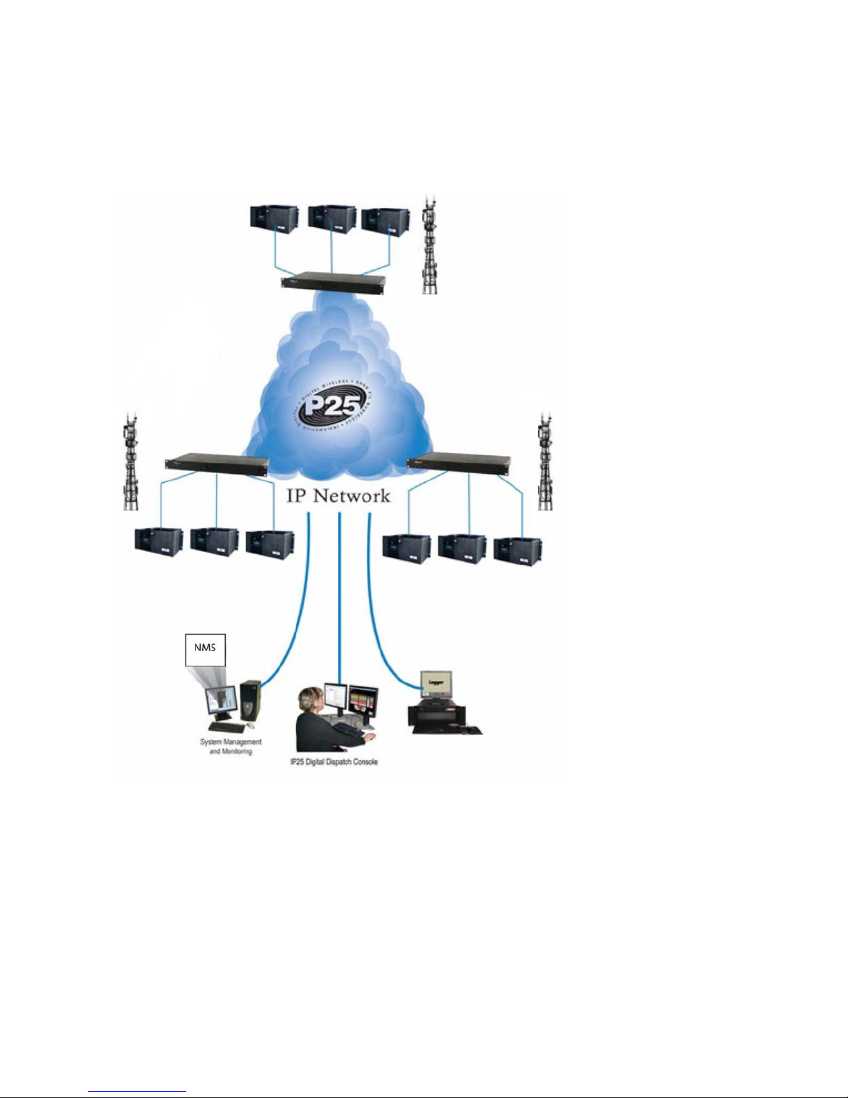
The 3800 Repeater is typically used as the repeater component in an EF Johnson Technologies Trunked
IP25TM
Configuration of 3800 repeaters is performed through the Network Management System (NMS). Refer to
Section 3.3, “Trunked System Operation”in this manual for system operating information.
System. This is an Internet Protocol (IP) Local Area Network (LAN) based radio system. Using a
IP network configuration lets a system administrator manage the radios and system components exactly as
if they were computers on a LAN. See Figure 1.3.
3800 Information
1 -6 3800 Digital Repeater Operating Manual October 2009
Figure 1.3 Trunked IP25 System

3800 Information
October 2009 3800 Digital Repeater Operating Manual 1 -7
1.4 Safety Information
This repeater emits radio frequency (RF) energy when transmitting. Make sure to observe
all RF energy exposure standards when installing, testing, repairing, and operating this radio equipment.
The FCC has adopted a safety standard for human exposure to RF energy. Proper operation of this
repeater under normal conditions results in user exposure to RF energy below the Occupational Safety
and Health Act and Federal Communication Commission limits.
-Do not allow the antenna to touch or come in very close proximity with the eyes, face, or any
exposed body parts while the repeater is transmitting.
-To comply with FCC RF exposure limits, do not operate the transmitter of a stationary radio (base
station or marine radio) when a person is within fourteen (14) feet [four (4) meters] of the antenna.
-Do not operate the repeater in explosive or flammable atmospheres. The transmitted repeater energy
could trigger blasting caps or cause an explosion.
-Do not operate the repeater without the proper antenna installed.
-Do not allow children to operate transmitter equipped repeater equipment.
Note The above warning list is not intended to include all hazards that may be encountered
when using this repeater.
This device complies with Part 15 of the FCC rules. Operation is subject to the condition that this device
does not cause harmful interference. In addition, changes or modification to this equipment not expressly
approved by EF Johnson Technologies could void the user’s authority to operate this equipment (FCC
rules, 47CFR Part 15.19).
The information in this document is subject to change without notice. EF Johnson Technologies will not
be liable for any misunderstanding due to misinformation or errors found in this document.
1.5 More Information
Additional information is available for the 3800 Digital Repeater. Contact your supervisor, site radio
administrator or EF Johnson Technologies representative should you need one of these additional
manuals. Refer to the following:
-EF Johnson Technologies 3800 Digital Repeater Installation Manual

3800 Information
1 -8 3800 Digital Repeater Operating Manual October 2009
-EF Johnson Technologies 3800 Digital Repeater Service Manual
-EFJohnson Trunked IP25 System Installation & Configuration Manual
-EFJohnson Trunked IP25 System Administration & Maintenance Manual
October 2009 3800 Digital Repeater Operating Manual 2 -1
Section
2
Section 2Controls & Indicators
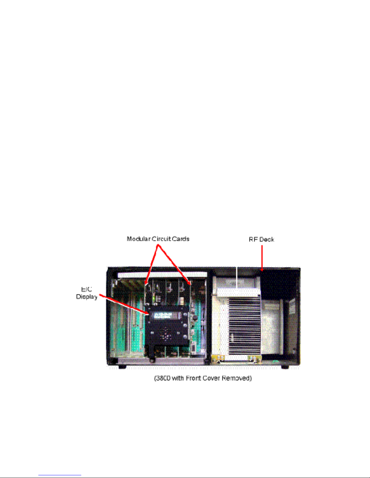
Most controls and indicators on the 3800 are located behind the front panel. Figure 2.1 shows the 3800 with its front
panel removed. 3800 controls and indicators are located on the Site Controller card, Channel Controller card, and the
External Interface card. These are described and illustrated in greater detail in the following sections.
Figure 2.1 3800 Repeater with Front Panel Removed
Controls & Indicators
2 -2 3800 Digital Repeater Operating Manual October 2009
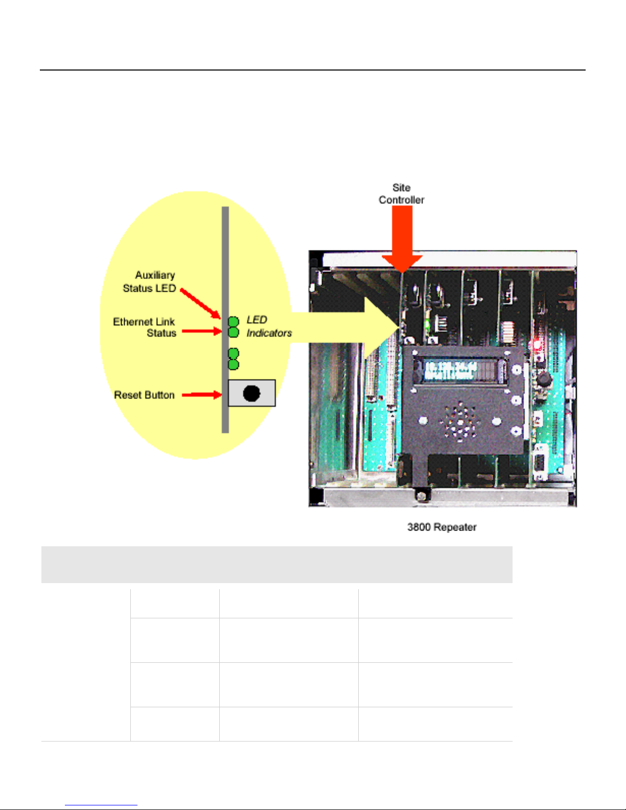
2.1 Site Controller Card
The site controller card provides the high-level call processing for the entire site. Unless using backup site controllers,
only one repeater in each system contains a site controller card. The Site Controller card’s controls and indicators are
illustrated in Figure 2.2 and described following.
Figure 2.2 Site Controller Controls and
Indicators
Site Controller Controls and Indicators
Auxiliary Status LED
LED Indication
Software Version < 3.0
Software Version > or = 3.0
On Solid
Ethernet link datarate = 100 Mbps
Site controller is in standby as redundant
controller.
Flashing
NA
Site Controller is active in Trunking
Mode.
Off
Ethernet link datarate = 10 Mbps
NA
Controls & Indicators
October 2009 3800 Digital Repeater Operating Manual 2 -3
Ethernet Link Status
This indicates the main Ethernet link data rate. If this LED is on, the rate is 100 Mbps. If this LED is off,
the rate is 10 Mbps.
Reset Switch
Pressing this switch resets the controller card.
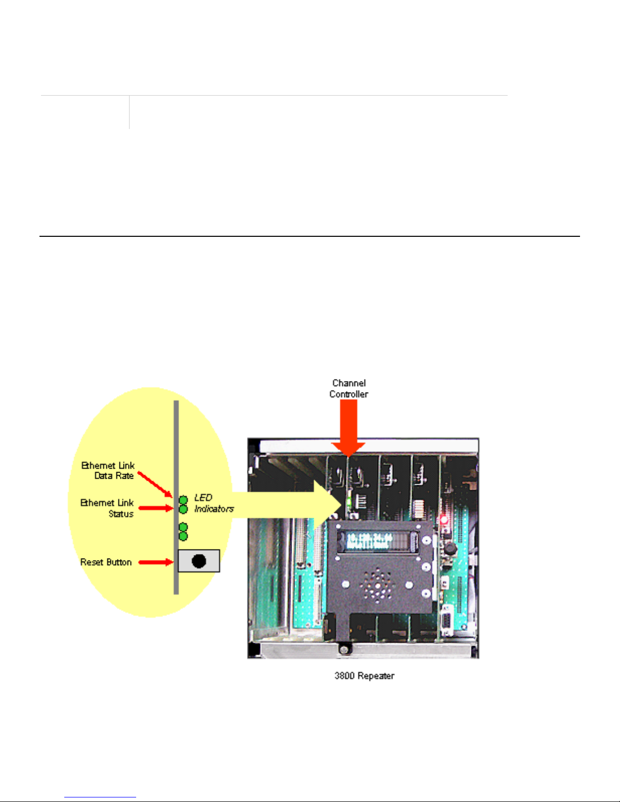
2.2 Channel Controller Card
The channel controller card controls either a single traffic channel or a single control channel for a particular 3800
repeater system. The Channel Controller card’s controls and indicators are illustrated in Figure 2.3 and described
following.
Figure 2.3 Channel Controller Card Controls and Indicators

Controls & Indicators
2 -4 3800 Digital Repeater Operating Manual October 2009
Channel Controller Controls and Indicators
Ethernet Link Data Rate LED
This indicates the main Ethernet link data rate. If this LED is on, the rate
is 100 Mbps. If this LED is off, the rate is 10 Mbps.
Ethernet Status LED
If on, the repeater is connected to Ethernet.
Reset Switch
Pressing this switch resets the channel controller card.
Note Both of the Channel Controller card LEDs should be ON continuously after you initialize the repeater.
(Two LEDs are not used in the field.)
Controls & Indicators
October 2009 3800 Digital Repeater Operating Manual 2 -5
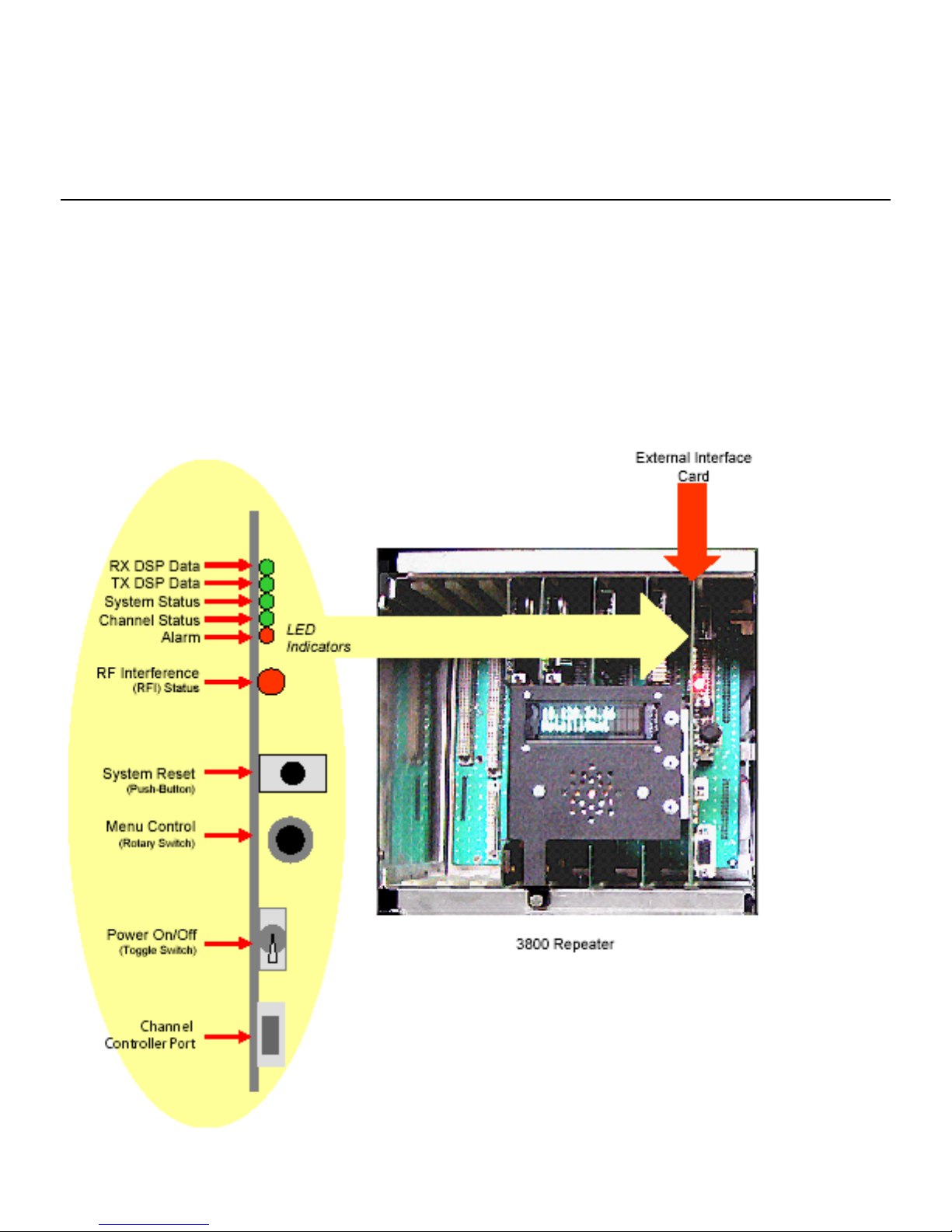
2.3 External Interface Card (EIC)
The External Interface Card (EIC) contains most of the switches and LEDs that you use to monitor and control the
repeater. The EIC controls only the channel controller card. These controls and indicators are illustrated in Figure 2.4
and described as follows.
Note LED indications discussed here apply only during normal operation (i.e., not during diagnostics)
EIC Controls and Indicators

Controls & Indicators
2 -6 3800 Digital Repeater Operating Manual October 2009
EIC Controls and Indicators
RX DSP Data LED
When ON, receiving decodable data.
•Control channel –
RX synthesizer is locked, receiving decodable user
registrations, affiliations or call requests
•Traffic channel – RX synthesizer is locked, receiving user voice
traffic. This LED flickers as users key and dekey, enter and exit
fades, etc.
TX DSP Data LED
When ON, transmitter is active.
•Control channel – TX synthesizer is locked, PA is keyed up, no RF
deck alarms. This LED is on continuously unless there is a failure
condition
•Traffic channel – TX synthesizer is locked, PA is keyed up with user
voice, no RF deck alarms. This LED is on for the duration of a voice
call. During fail-soft operation, this LED is on continuously.
System Status LED
When ON, system is operating properly.
This LED indicates that all tasks are reporting in to the watch dog timer.
As long as all tasks are reporting in, this LED is on. If a failure occurs,
the LED is off.
Channel Status LED
When ON, repeater is operationally active and in service.
This LED is on while a repeater is administratively and operationally
active. If configuration is corrupted resulting in the repeater being
unusable, the LED is off.
Alarm LED
When ON, a Critical alarm is pending.
This indicates that service is required. An example would be an RF
transmitter failure.
RF Interference (RFI)
Status
Flashing Green
RFI Detection Disabled
Solid Green
RFI Detection Enabled: no RFI detected
Solid Orange
RFI Detection Enabled: Alarm level RFI
detected
Solid Red
RFI Detection Enabled: Disable level RFI
detected
Flashing Red
RFI Detection not supported

Controls & Indicators
October 2009 3800 Digital Repeater Operating Manual 2 -7
System Reset Switch
This is the reset switch for both the channel controller and the site
controller (if one is installed). Pressing this switch resets the control
logic and restarts the operating program(s) from the beginning.
Menu Control Switch
Pressing or rotating this control enables the menu mode. When the
menu mode is selected, pressing and rotating this control scrolls
through and selects the various menus and parameters.
Power On/Off Switch
Turns repeater power on and off. It connects to the power supply remote
enable line and switches the main power supply power sources.
Channel Controller Port
RS232-C jack that connects to channel controller processor.
Display
This 2 line x 16 character vacuum fluorescent display can indicate the
following information:
•On power-
up, it indicates the various sequences that are executed by
the control logic as the operating program starts.
•During normal operation, the display indicates
•The repeater name
•Whether the repeater’s channel is a voice channel (V) or a control
channel (C)
•The repeater’s IP address

October 2009 3800 Digital Repeater Operating Manual 3 -1
Section
3
Section 3Operation
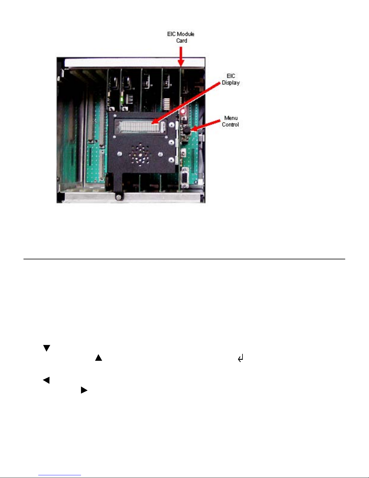
3.1 Operational Interface
The External Interface Card (EIC) module provides the primary manual interface to setup and operate the 3800
Repeater. Using the two-line display, the EIC provides a menu structure of functions and settings for operating the
repeater. (See Figure 3.1.)
Figure 3.1 3800 EIC Interface
Operation
3 -2 3800 Digital Repeater Operating Manual October 2009
3.2 EIC Menu Modes
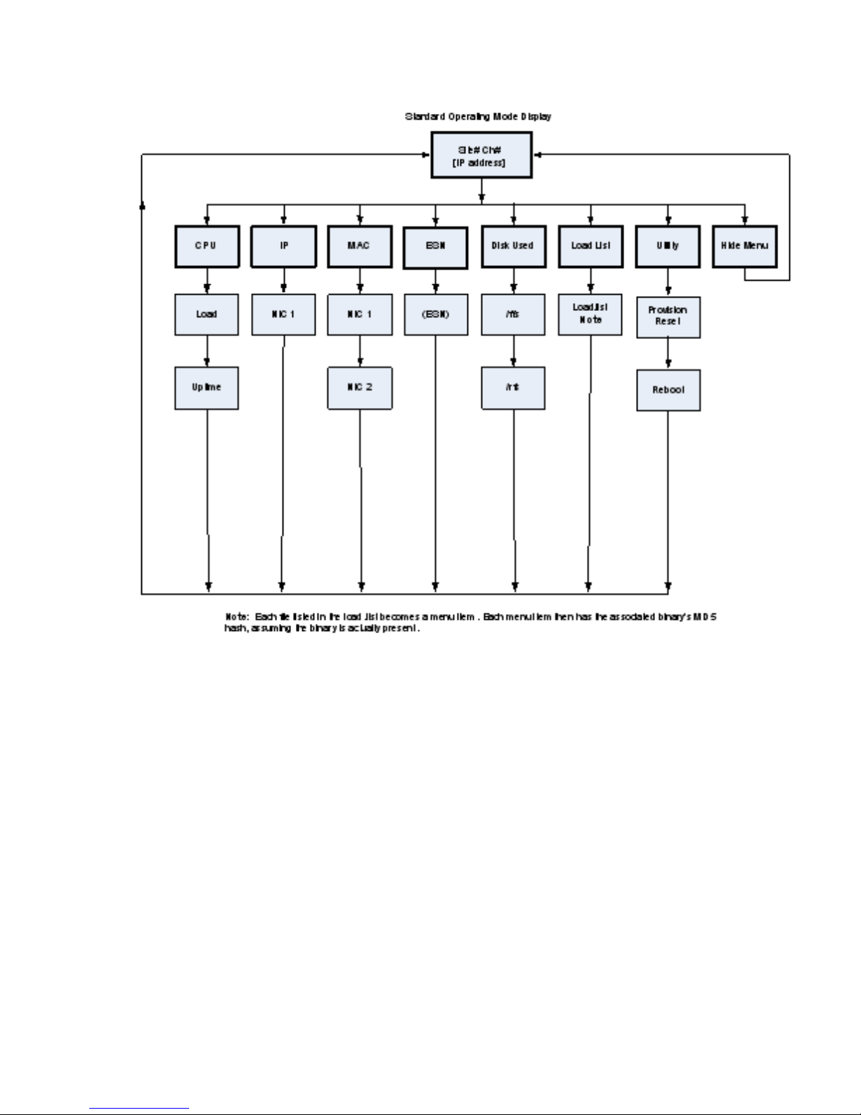
The main menu mode can be selected to display various repeater parameters. Figure 3.2 is a block diagram of the menu
mode struct
The menu mode is selected and controlled by the Menu Control knob as follows.
ure.
•To select the menu mode, press or rotate the Menu Control knob. The first main menu “CPU” is then displayed.
•In general, rotating the Menu Control scrolls through available parameters, and pressing it selects the displayed
parameter.
•The icon in the upper right corner of the display indicates that if the knob is pressed, the next lower menu level is
selected. Conversely, if is displayed, the next higher level is selected. The icon indicates that the displayed
parameter or function is selected.
•The icon in the left-most position of the bottom line indicates that additional parameters have scrolled off to the
left. Likewise, the icon in the right-most position indicates additional parameters have scrolled off to the right.
•Selecting [Back] returns a level up in menu hierarchy.
Operation
October 2009 3800 Digital Repeater Operating Manual 3 -3
Figure 3.2 Main Menu Mode Block
Diagram
Note The repeater also has a diagnostic menu mode. Refer to Section 4 of this manual for a description of
this mode.

Operation
3 -4 3800 Digital Repeater Operating Manual October 2009
3.2.1 CPU Menu
This menu displays CPU information.
-Load - Current system load.
-Uptime -Length of time in seconds that the CPU has been running.
3.2.2 IP Menu
This menu displays the Internet protocol (IP) address associated with the repeater.
-NIC1 -The first network interface card. Some repeaters may have more than one network interface card.
3.2.3 MAC
This menu displays the MAC information for the repeater.
-NIC1
-
- The first network interface card. Some repeaters may have more than one network interface card.
NIC2
3.2.4 ESN
- The second network interface card.
This menu displays Electronic Serial Number (ESN) information for the repeater.
-(ESN)
3.2.5 Disk Used Menu
- Electronic Serial Number for the repeater.
This menu shows the amount of used disk space (disks) for each item in the menus below this menu.
-/ffs - Shows disks used for /ffs (Flash file system).
-/rfs - Shows disks used for /rfs (RAM file system).

Operation
October 2009 3800 Digital Repeater Operating Manual 3 -5
3.2.6 Load List Menu
This menu displays the list of items in current load list.
-load.lst - Shows the last digits of the MD5 hash for the /ffs/etc/load.lst file. Each line in this file becomes a menu
item. Each menu item then has the associated binary’s MD5 hash, assuming the binary is actually present.
Note Shows the cumulative MD5 hash for all binaries listed in the load.list.
3.2.7 Utility Menu
This menu provides access to various utility functions for the system.
-Provision Reset - Replaces manifest files currently installed on the board
(/ffs/etc/site.maf and /ffs/etc/site.maf.md5) with updated files from the NMS.
-Reboot - Reboots the channel controller without regard for the current state.
Tip To reboot the channel controller, it is preferable to use this command rather than to press the Reset switch.
Note
3.2.8 Hide Menu
When you reboot the channel controller, the reboot may not happen immediately. The reboot may require several
seconds.
This menu exits the menu mode.
3.3 Trunked System Operation
When used in a Trunked IP25 System infrastructure, the 3800 repeater communicates all control and status to the
Network Management System (NMS). All system control setup is through the NMS.
Refer to the EFJohnson Trunked IP25 System Administration & Maintenance manual for additional information on
3800 Repeater operation in a system infrastructure.
Table of contents


