EFA 53 Manual

Schmid & Wezel
D 75433 Maulbronn
Ausführung/ Version
08.2011
Wichtige Informationen:
Diese Anleitung unbedingt dem Bedienpersonal aushändigen!
Important Informations:
Please forward these operating instructions to your operating
personell!
Betriebsanleitung/ Operating instructions
Wartungsanleitung/ Maintenance instructions
Ersatzteilliste/ Sparepart list
EFA 53
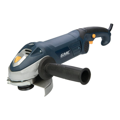
Häutermesser- Schleifmaschine
Knifesharpening- machine

Schmid & Wezel
D 75433 Maulbronn
Seite/ Page
1
Ausführung/ Execution
08.2011
INHALTSVERZEICHNIS
1. Verwendung, Lieferumfang, Zubehör....................................................................................2
1.1 Symbole in dieser Anleitung.........................................................................................................2
1.2 Bestimmungsgemäße Verwendung...............................................................................................2
1.3 Lieferumfang ..............................................................................................................................2
1.4 Zubehör .....................................................................................................................................2
2. Sicherheitshinweise...............................................................................................................2
2.1 Allgemeine Sicherheitshinweise....................................................................................................2
2.2 Verhalten am Arbeitsplatz............................................................................................................2
3. Inbetriebnahme und Vorarbeiten..........................................................................................3
3.1 Reinigen der Häutermesser..........................................................................................................3
3.2 Prüfen der Messerbuchsen...........................................................................................................3
3.3 Einstellen....................................................................................................................................3
3.4 Richten der Häutermesser............................................................................................................3
3.5 Kontrolle auf Maß........................................................................................................................3
4. Arbeiten mit EFA53................................................................................................................3
4.1 Voreinstellung.............................................................................................................................4
4.2 Zahnprofil schleifen.....................................................................................................................5
4.3 Freischleifen der Messerinnenseite................................................................................................5
5. Wartung.................................................................................................................................5
6. Technische Daten ..................................................................................................................6
A. Anhang ..................................................................................................................................7
A.1 Liste der Ersatz- und Verschleisteile..............................................................................................7
A.2 Explosionszeichnung ...................................................................................................................9
B. Konformitätserklärung ........................................................................................................11

Schmid & Wezel
D 75433 Maulbronn
Seite/ Page
2/ 11
Ausführung/ Version
08.2011
1. Verwendung, Lieferumfang,
Zubehör
Hinweise, unbedingt lesen!
Diese Anleitung richtet sich an den Maschinenbedie-
ner. Bewahren Sie sie gut auf!
Die Schleifmaschine darf nur betrieben werden:
in technisch einwandfreiem Zustand bestim-
mungsgemäß sowie sicherheits- und gefahren-
bewußt
mit allen angebauten Sicherheitseinrichtungen
gemäß den Sicherheitshinweisen
nachdem das Bedienpersonal diese Anleitung,
insbesondere Kapitel 2 "Sicherheitshinweise" (S.
2) und Kapitel 3 "Inbetriebnahme und Vorarbei-
ten" (S. 3) gelesen und verstanden hat
Nur so können Fehlbedienungen vermieden und Ge-
fahrensituationen richtig eingeschätzt werden.
1.1 Symbole in dieser Anleitung
Gefahrensymbol:
Hier ist äußerste Vorsicht und Umsicht
geboten. Bei Fehlverhalten besteht di-
rekte Verletzungsgefahr für das Be-
dienpersonal oder Dritte. Außerdem
kann die Maschine Schaden nehmen.
Informationssymbol:
Mit diesem Symbol versehene Textpas-
sagen geben Ihnen wichtige Informa-
tionen und nützliche Tipps.
1.2 Bestimmungsgemäße Verwen-
dung
Die Häutermesser- Schleifmaschine EFA 53 wurde
speziell zum Schleifen von EFA- Häutermessern der
Enthäuter 300, 610 und 620 konstruiert. Es ist un-
bedingt zu unterlassen, Handmesser, Hackbeile und
ähnliche Werkzeuge mit diesen Spezialscheiben zu
bearbeiten.
1.3 Lieferumfang
Schleifmaschine EFA 53
Betriebsanleitung
1.4 Zubehör
Die Bestellnummern sowohl für im Lieferumfang
enthaltene Teile wie für Zubehör finden Sie in An-
hang A1 (Liste der Ersatz und Verschleißteile).
2. Sicherheitshinweise
Während des Schleifens ist eine Schutzbrille zu
tragen.
Häutermesser niemals ruckartig an die Schleif-
maschiene führen.
Schutzhaube darf nicht entfernt werden.
2.1 Allgemeine Sicherheitshinweise
Befolgen Sie beim Gebrauch der Schleifma-
schine unbedingt nachfolgende Sicherheits-
maßnahmen.
Für die Bedienung wird vorausgesetzt, dass das
Bedienpersonal ausreichende Kenntnisse zum
Arbeiten mit der Schleifmaschiene hat.
Achten sie darauf, dass die Maschine stets in
einem betriebssicheren Zustand gehalten wird
und tauschen Sie defekte Teile, welche die
Betriebssicherheit gefährden könnten, unver-
züglich aus.
Verwenden sie nur EFA- Originalzubehör. Ein
Gebrauch anderer Einsatzwerkzeuge oder Zube-
höre kann verletzungsgefährlich für Sie sein.
Werden keine EFA- Originalersatzteile verwen-
det, erlischt der Garantieanspruch.
Installations-, Wartungs- und Reparaturarbei-
ten dürfen nur von autorisiertem Fachpersonal
durchgeführt werden
Technische Veränderungen oder Umbauten an
der Anlage sind grundsätzlich nicht zulässig und
entbinden S&W von jeglicher Gewährleistung
und Haftung.
Die Anlage darf nur betrieben werden, wenn alle
Schutz- und Sicherheitseinrichtungen vorhanden
sind und einwandfrei funktionieren.
2.2 Verhalten am Arbeitsplatz
1. Halten Sie Ihren Arbeitsplatz in Ordnung.
Unordnung kann Unfälle zur Folge haben.
2. Berücksichtigen Sie Umgebungseinflüsse. Sor-
gen Sie für gute Beleuchtung (min. 500 Lux).
3. Schleifgerät nur ausgeschaltet an das Netz
anschließen.
4. Im eingeschalteten Zustand besonders vorsich-
tig sein. Nicht in den Schleifscheibenbereich
greifen oder Messerschneiden berühren.
5. Niemals Messer einsetzen oder entfernen, wäh-
rend Schleifscheibe läuft.

Schmid & Wezel
D 75433 Maulbronn
Seite/ Page
3/ 11
Ausführung/ Version
08.2011
6. Arbeitskleidung: Tragen Sie keine weite Klein-
dung oder Schmuck - diese können von beweg-
lichen Teilen erfasst werden. Tragen Sie beim
Arbeiten festes Schuhwerk. Tragen Sie generell
ein Haarnetz!
7. Vermeiden Sie eine nicht normale Körperhal-
tung. Sorgen Sie für sicheren Stand und halten
Sie jederzeit das Gleichgewicht.
8. Pflegen Sie Ihre Werkzeuge mit Sorgfalt.
9. Motor nach Einsatz sofort abschalten.
10.Lassen Sie keine Werkzeugschlüssel stecken.
Überprüfen Sie vor dem Einschalten, ob alle
Schlüssel entfernt sind.
11.Vor allen Wartungs- und Reparaturarbeiten und
vor dem Schleifscheibenwechsel, Schleifgerät
vom Stromnetz trennen.
12.Zum Schleifen Schutzbrille tragen.
13.Tragen sie während des Betriebes der Anlage je
nach Gräuschpegel den vorgeschriebenen
Gehörschutz.
14.Das Motorengehäuse darf niemals angebohrt
werden. Verwenden sie Klebeschilder zur Kenn-
zeichnung des Gerätes.
3. Inbetriebnahme und Vorar-
beiten
Arbeitsplatz
Der Arbeitsbereich für den Bediener sollte minde-
stens 1,5 qm groß sein. In diesen Bereich sollte kein
anderer Arbeitsplatz hineinragen.
DieBeleuchtung desArbeitsplatzesmussmin.500
Lix entsprechen.
3.1 Erstinbetriebnahme
3.1.1
Vor der Inbetriebnahme ist darauf zu achten, das
die Netzspannung mit der auf dem Typenschild an-
gegebenen Spannung übereinstimmt. Durch kurzes
Einschalten des Gerätes ist zu prüfen, ob der Motor
in die mit dem Pfeil markierte Drehrichtung läuft
(sonst entsprechend Anschluss der 3 Phasen im
Stecker ändern).
3.1.2
Die Häutermesser lassen sich in der Regel 10 bis 15
mal nachschärfen. Die Profilscheibe (65) und die
Topfscheibe (64) bestehen aus einem Stahlkörper,
welcher an den Schleifflächen mit dem Schleifmittel
Borazon beschichtet ist. Ein Abrichten oder Nachfor-
men der Schleifscheiben ist verboten. Sie bringen
maximale Oberflächengüte und Standzeit der Häu-
termesser und haben selbst eine, im Vergleich zu
anderen Schleifmitteln, nicht erreichte Standzeit.
Die schleifmaschine nur in ausge-
schaltetem Zustand an das Be-
triebsnetz anschließen.
Aufgrund des Gewichts von ca. 17
kg kann es beim Aufstellen der
Maschine zu einer Gefärdung
kommen. Achten sie auf eine ge-
sundheitsbewusste Haltung beim
Heben und Aufstellen der Maschine und des
ca. 14 kg schweren Necessaire- Koffers.
Prüfen Sie ob die Messer schärfbar sind, d.h.
Zahngrund entpricht min. Lauffläche.
Prüfen sie die Messerbüchse mit einem neuen
Pleuel auf Maß. Pleuel muss laufbar sein.
Achten sie darauf, dass die Messerbüchse fest
im Messer sitzt.
3.2 Paarweise Bearbeitung
Werden stumpfe Häutermesser gegen scharfe aus-
gewechselt, so darf dies immer nur als Messerpaar
geschehen. Messer nur paarweise schärfen!
3.3 Reinigen der Häutermesser
Mit heißem Wasser und Bürste, in hartnäckigen Fäl-
len mit konzentriertem Lösungsmittel. Es ist zu ver-
meiden, harte Gegenstände zum Abkratzen von
Rückständen zu verwenden.
3.4 Prüfen
3.4.1 Messerbuchse prüfen
Führt man einen neuen Pleuelarm in die Messer-
buchse ein und hat dieser zu viel Spiel, so muss die
Messerbuchse ausgetauscht werden. Zum Aus-
tausch der Messerbuchse, Auflage (90) in Richtklotz
(86) einstecken. Häutermesser mit dem Bund nach
unten in die Bohrung der Auflage (90) legen. Nun
mit passendem Stempel Messerbuchse mit einigen
Hammerschlägen aus Häutermesser treiben. (Abb.
7)

Schmid & Wezel
D 75433 Maulbronn
Seite/ Page
4/ 11
Ausführung/ Version
08.2011
Zur Montage der neuen Messerbüchse Auflage (89)
in den Richtklotz (86) einstecken; Messerbüchse mit
Bund nach unten oben auflegen und mit ca. 400g
schwerem Schlosserhammer die Büchse ins Messer
einschlagen Mit leichten Schlägen der Hammerfin-
ne, auf das Häutermesser rund um die messerbüch-
se, wird die Messerbüchse eingetrieben, bis sie mit
dem Bund plan an EFA- Häutermesser anliegt.(Abb.
8)
Messerbüchse für Reperatur EFA620: 003 005 589
3.4.2 Vorspannung prüfen
Messerhöhe (Vorspannung) prüfen. Meßplatte (80)
und Kleinmessuhr(85) mittels Prüfscheibe (91) und
Meßplatte (98) auf Abstandsmaß 1,65 eingerichten.
(Meßuhr drehen bis Zeiger auf 0 steht. Abb.1)
3.4.3 Häutermesser prüfen
Nun wird anstelle der Prüfscheibe (91) das Häuter-
messer auf die Meßplatte (98) gelegt und unter dem
Taststift der Meßuhr durchgeführt. Die Maßabwei-
chung ist an der Kleinmessuhr (85) ablesbar. 0 bis
+0.1 ist gut. Bei Minustoleranz muß man das Messer
richten. (Abb.2 )
3.5 Richten der Häutermesser
Messerplanseite liegt auf dem Richtklotz (86) nach
oben. Die Messerbüchse ist in der Bohrung des
Richtklotzes versenkt. Mittels Richtklotz und Richt-
hammer (92) wird das Häutermesser nachgerichtet.
(Abb.3)
Es ist zu beachten, dass um die Mittelbohrung mög-
lichst wenige Richtschläge geführt werden. Bei
nichtbeachtung kann das Häutermesser beschädigt
werden. Vergleichen sie mit den Richtmarken auf
der Innenseite eines neuen Messerpaares. (Abb.5)

Schmid & Wezel
D 75433 Maulbronn
Seite/ Page
5/ 11
Ausführung/ Version
08.2011
4. Arbeiten mit der Häutermes-
ser- Schleifmaschine EFA 53
Die Häutermesser sind als Paar im Enthäuter einge-
baut und müssen auch bei jedem Nachschärfen als
Paar bearbeitet werden. Beim Nachschleifen des
Zahnprofils wird das zweite Messer bis zum selben
TeilstrichanderZustellspindel (55) nachgestellt und
geschliffen, wie das erste Messer des Paares.
4.1 Voreinstellung
Der Schwenkhebel (27) mit der Messerauflage (41)
muss auf Zahnmitte der Profilscheibe (65) einge-
stellt sein.
Zur Einstellung, Mutter (38) lösen und mit Innen-
sechskantschlüssel SW10 Spindel verstellen. nach
Einstellen, Mutter (38) wieder anziehen.
4.2 Zahnprofil schleifen
4.2.1
Klemmhebel (57) lösen, Schwenklager (40) in unte-
re Endstellung klappen (siehe Pos ’a’ Explosions-
zeichnung, Anhang A) und Klemmhebel(57) wieder
festziehen.
4.2.2
Klemmhebel (53) mit Zylinderstift so drehen, dass
diese als Sperre in eine der 4 Kerben der Messerauf-
lage (41) einrastet. Bei festgehaltenem Klemmhe-
bel, Spanngriff abschrauben und EFA-
Häutermesser mit Büchsenbund in Ausparung der
Auflage (41) einlegen, d.h. so, dass die Seite, auf
welcher die Messer aufeinandergleiten, oben liegt.
Spanngriff (56) auf Bolzen der Auflage (41) auf-
schrauben und Häutermesser unverrückbar anzie-
hen. Schleifrichtung von links nach rechts gehend,
so dass Fixierhebel (51) immer in ungeschliffene
Zahnlücke greift. Klemmhebel nach unten drücken,
Messerzahn weiterdrehen und neu fixieren.
4.2.3
Schwenkhebel (27) gegen Profilscheibe (65) führen
(siehe Pos ’d’ Explosionszeichnung, Anhang A), Zu-
stellspindel (55) so einstellen, dass Schleifscheibe
(65) frei läuft. Motor einschalten, Messer an Profil-
scheibe zuführen bis Abtrag an Zahn erkennbar. In
dieser Stellung Zustellspindel (55) stehen lassen!
Nun 5-10 Zähne schleifen. Danach Messer Ausbau-
en und Zahnprofil kontrollieren (siehe nachfolgende
Zeichnung und Tabelle).
4.2.4
Alle Messerzähne Komplett schleifen, bei gleichblei-
benderSchleiftiefe.ZustellungmittelsZustellspindel
(55). Rechtsdrehung verringert Schleiftiefe, Links-
drehung erhöht Schleiftiefe.
4.2.5
Um eine Beschädigung an den Tierhäuten zu ver-
meiden, Zahnspitzen trimmen/ abstumpfen:
Motor ausschalten!
Klemmhebel(57) lösen und Konsole hochklap-
pen. (siehe Pos ’b’ Explosionszeichnung, Anhang
A) Klemmhebel(57) wieder feststellen.
Zustellspindel einstellen bis Schleifscheibe frei
ist (siehe Pkt. 4.2.3).
Motor einschalten.
Nun Zustellspindel zustellen bis ein leichter
Abtrag an der Zahnspitze erkennbar ist.
4.3 Freischleifen der Messerinnen-
seite
Häutermesser mit dem magnetischen Messerhalte-
griff (60) aufnehmen und Messerbüchse mit Stift
zentrieren. Halter (60) mit Messer auf Spannhülse
zentrieren. An Topfschleifscheibe (64) andrücken
und um Spannhülse (24) hin- und herschwenken,
Tabelle 1: Zahnprofile
1Zahnprofil in Ordnung: Weiter zu
4.2.4
2
Zahnprofil zu lang: Klemmhebel
(57) lösen und zurückschrauben.
Stiftschraube (b) eindrehen, bis
Zahnprofil i.O. und Mutter festzie-
hen.
3
Zahnprofil zu kurz: Klemmhebel
(57) lösen und Stiftschraube (b)
herausdrehen bis Zahnprofil i.O.
und Mutter festziehen.

Schmid & Wezel
D 75433 Maulbronn
Seite/ Page
6/ 11
Ausführung/ Version
08.2011
biseingleichmäßigtragendesSchleifbild erreichtist.
Jeder einzelne Zahn muß außen tragen um einen
einwandfreien Schnitt zu erreichen. Das Schleifbild
muss an allen Zahnspitzen sichtbar sein.
4.3.1 Messer auf Maß kontrollieren.
Maß 1,65 (+0,05) kontrollieren. Falls das Maß
stimmt, ist das Messer fertig. Andernfalls Messer
nachrichten und Planschleifen wiederholen. ( Zahn-
profil muß nicht nachgearbeitet werden)
5. Wartung
Die Borazonschleifscheiben sind auf Metall-
trägern aufgebracht, sie dürfen
während ihrer ganzen Lebensdau-
er nicht abgerichtet oder profiliert
werden; dies hätte die Zerstörung
der Schleifscheiben zur Folge!
Bei Schmutzablagerungen auf der Borazonschicht
muss diese von S&W neu beschichtet werden!
Die Schleifmaschine EFA 53 ist staubfrei und sauber
zu halten, sie ist allgemein Wartungsfrei.
6. Technische Daten
Tabelle 2:
Spannung 220/ 380 V Drehstrom
Frequenz 50 Hz
Leistungsauf-
nahme 250 W (0,34 PS)
Drehzahl 2900/min
Gewicht 17 kg

2. Anhang
Pos.-Nr. Menge Benennung Artikel-Nr.
EFA 53 DS 220/380V 130 105 300
1 1 Motor CPL. 008 002 732
1.1 1 Sechskantmutter 002 000 100
1.2 1 Scheibe 003 010 845
1.3 1 Profilscheibe VST 007 002 735
1.4 1 Spannscheibe 003 002 734
1.5 4 Zylinderschraube 001 320 208
1.6 1 Zylinderschraube 001 320 217
1.7 1 Schutzhaube 003 002 732
1.8 1 Anschlag003 002 733
1.9 1 Federring 001 311 007
1.10 1 Motor vst 007 002 732
1.10.1 1 Motorgehäuse Links 003 013 462
1.10.2 2 Rillenkugellager 001 340 259
1.10.3 1 Schalterblende 001 605 308
1.10.4 2 Senkschraube DIN 964 001 326 428
1.10.5 1 Schalter001 606 919
1.10.6 1 Stator 003 013 467
1.10.7 1 Klemme 001 605 601
1108 1Fd i 001 317 007
2.1 Liste der Ersatz- und Verschleißteile
SchmidWezel
D‐75433Maulbronn
Seite/Page
711Ausführung/Execution
08.2011
1.10.8 1 Federring
1.10.9 1 Zylinderschraube 001 326 101
1.10.10 1 Rotor 007 013 463
1.10.11 1 Wellenfederring001 314 603
1.10.12 1 Motorgehäuse Rechts 003 013 461
1.10.13 2 Zylinderschraube 001 320 219
1.10.14 1 Kabelverschraubung001 325 556
1.10.15 1 Spannhülse 003 002 737
1.10.16 1 Topfscheibe VST 007 002 736
1.10.17 1 Gummischlauchleitung 001 601 711
2 1 MesserhalterungVST007 000 599
3 1 Aufbau CPL 008 002 715
3.1 1 Sockel VST. 007 002 715
3.1.1 1 Sockel 003 002 715
3.1.2 4 T-Puffer EFA 001 352 201
3.1.3 4 Scheibe 001 310 003
3.1.4 4 Zylinderschraube 001 320 208
3.2 1 Schwenklager CPL 008 002 717
3.2.1 1 Schwenklager 003 002 717
3.2.2 1 Kippklemmhebel VST007 004 521
3.2.3 1 Beilagscheibe 001 361 615
3.2.4 1 Auflage 003 002 725
SchmidWezel
D‐75433Maulbronn
Seite/Page
7/
Ausführung/Execution
08.2011

3.2.5 1 Fixiereinheit 003 002 730
3.2.6 1 Spiralspannstift 001 307 302
3.2.7 1 Feder 003 002 739
3.2.8 2 Tellerfeder 001 314 106
3.2.9 2 Rillenkugellager 001 343 206
3.2.10 1 Distanzbuechse 003 002 723
3.2.11 1 Distanzbuechse 003 002 722
3.2.12 1 Deckel 003 002 726
3.2.13 2 Senkschraube 002 000 176
3.2.14 1 Schlitzmutter001 301 213
3.2.15 2 Rillenkugellager 001 345 323
3.2.16 1 Zustellspindel VST 007 002 727
3.3 1 Klemmhebel VST. 007 002 724
3.3.1 1 Distanzscheibe 003 002 724
3.3.2 1 Kipp-Klemmhebel 001 325 101
3.3.3 1 Spannbüchse 003 002 731
3.4 1 Spanngriff 003 001 085
3.5 4 Federring 001 310 909
3.6 2 Spannstift 001 307 304
3.7 4 Zylinderschraube 001 320 219
3.8 1 Schwenkhebel CPL 008 002 716
3.8.1 1 Schwenkhebel VST. 007 002 716
3.8.1.1 1 Schwenkhebel 003 002 716
3.8.1.2 1 Sechskantmutter
SchmidWezel
D‐75433Maulbronn
Seite/Page
Ausführung/Execution
08.2011
3.8. 001 300 003
3.8.1.3 1 Gewindestift 001 322 401
3.8.1.4 1 Kunststoffkugel 001 342 829
3.8.2 1 Spindel 003 002 718
3.8.3 2 Rillenkugellager 001 345 303
3.8.4 1 Distanzbuechse 003 002 721
3.8.5 2 Tellerfeder001 314 111
3.8.6 1 Schlitzmutter 001 301 215
3.8.7 1 Deckel 003 002 719
3.8.8 11 Senkschraube 002 000 176
3.8.9 2 Lagerbolzen 003 002 720
3.8.10 1 Sechskantmutter 001 304 813
41Typenschild 003 009 290
5 4 Halbrundkerbnagel001 306 502
6 1 Richtungspfeil 003 002 235
7 1 Aufkleber 001 625 308
Zubehör, in Lieferumfang
enthalten
1 Sechskantstiftschlüssel SW 6 001 365 104
1 Sechskantstiftschlüssel SW 10 001 365 106
1 Einmaulschlüssel SW 13 001 365 808
1 Einmaulschlüssel SW 19 001 365 812
SchmidWezel
D‐75433Maulbronn
Seite/Page
8/11 Ausführung/Execution
08.2011

1 Einmaulschlüssel SW 36 001 365 818
Sonderzubehör
1 Abziehstein 001 365 507
SchmidWezel
D‐75433Maulbronn
Seite/Page
9/11 Ausführung/Execution
08.2011
SchmidWezel
D‐75433Maulbronn
Seite/Page
9/
Ausführung/Execution
08.2011

ss
SchmidWezel
D‐75433Maulbronn
Seite/Page
10/11 Ausführung/Execution
08.2011

Schmid & Wezel
D 75433 Maulbronn
Seite/ Page
11/ 11
10
Ausführung/ Execution
08.2011
B. Konformitätserklärung

Schmid & Wezel
D-75433 Maulbronn
Ausführung/Execution
02.2013
Important Information:
Please forward these operating instructions to your operating
personell!
Wichtige Informationen:
Diese Anleitung unbedingt dem Bedienpersonal aushändigen!
Operating instructions/ Betriebsanleitung
Maintenance instructions/ Wartungsanleitung
Sparepart list/ Ersatzteilliste
EFA 53
Blade grinder for skinning blades
Häutermesser- Schleifmaschine

Schmid & Wezel
D-75433 Maulbronn
Seite/Page
1
Ausführung/Execution
02.2013
TABLE OF CONTENTS
1. Application, scope of delivery and accessories......................................................................2
1.1 Symbols used in this manual........................................................................................................2
1.2 Proper use..................................................................................................................................2
1.3 Scope of delivery.........................................................................................................................2
1.4 Accessories.................................................................................................................................2
2. Safety instructions.................................................................................................................2
2.1 General safety instructions...........................................................................................................2
2.2 Workplace safety ........................................................................................................................2
3. Commissioning and preparation of grinder...........................................................................3
3.1 Commissioning............................................................................................................................3
3.2 Machining of blade pairs..............................................................................................................3
3.3 Cleaning of skinning blades..........................................................................................................3
3.4 Inspection ..................................................................................................................................3
3.5 Flattening skinning blade.............................................................................................................3
4. Operation of the EFA53 skinning blade grinder.....................................................................3
4.1 Preliminary settings.....................................................................................................................4
4.2 Sharpening of tooth edge ............................................................................................................5
4.3 Grinding of inner blade side.........................................................................................................5
5. Maintenance ..........................................................................................................................5
6. Technical data........................................................................................................................6
A. Appendix................................................................................................................................7
A.1 List of spare and wear parts ........................................................................................................7
A.2 Explosion view............................................................................................................................9
B. Declaration of conformity....................................................................................................10

Schmid & Wezel
D-75433 Maulbronn
Seite/Page
2/11
Ausführung/Execution
02.2013
1. Application, scope of delivery
and accessories
Important notes!
This manual has been specifically compiled for
machine operators. Keep it near the machine for
future reference!
The blade grinder may only be operated
for the intended purpose, with due care as
regards safety, and if the equipment is in proper
working order
if all safety devices are properly mounted
according to the safety instructions in this
manual
after instruction of the operating personnel, who
must also have read and understood the
instructions in Chapter 2 "Safety instructions"
(page 2) and Chapter 3 "Commissioning and
preparation of grinder" (page 3).
This is necessary in order to prevent incorrect
operation and to enable operators to assess
potential risks accurately.
1.1 Symbols used in this
manual
Danger:
Proceed with extreme caution. In the event of
incorrect operation, there is a risk of
injury to operating staff and other
persons. There is also a risk of damage
to the machine.
Information:
This symbol highlights sections in the text
containing important information and useful hints.
1.2 Proper use
The EFA 53 blade grinder for skinning blades has
been specifically designed for the sharpening of EFA
skinning blades. Never use the special grinding
wheels to sharpen normal blades, chopping blades
or similar tools.
1.3 Scope of delivery
EFA 53 blade grinder
Operating manual
1.4 Accessories
The order numbers of all parts included in the scope
of delivery and of spare parts are listed in the
appendix A1 (List of spare and wear parts).
2. Safety instructions
Wear goggles during grinding.
Carefully place the skinning blade on the
grinding wheels, avoiding sudden movements.
Do not remove the protective hood.
2.1 General safety instructions
When operating the grinder, always adhere
to the following safety instructions:
Only personnel who have been properly trained
and instructed in the safe use of the blade
grinder may operate the machine.
Ensure that the grinder is at all times in proper
and safe working order. Replace defective parts
that might affect the operational safety of the
machine without delay.
Use only original EFA accessories. If other tool
inserts or accessories are used, there is an
increased risk of injury to the operator and
other persons. The use of spare parts other
than EFA original parts shall void the warranty.
Installation, maintenance and repair work may
only be carried out by suitably trained and
authorised specialists technicians.
It is prohibited to modify the machine in any
way. Schmid & Wezel rejects any liability for
damages arising from modified equipment.
The grinder must only be operated, if all
protective and safety devices are properly
mounted and in working order.
2.2 Workplace safety
1. Keep your workplace tidy.
2. Ensure that the workplace environment is
suitable for the use of the tool and properly
illuminated (min. 500 lx).
3. When connecting the grinder to the power
supply, ensure that it is switched off.
4. While the machine is switched on, proceed with
extreme caution. Do not reach into the
operating range of the grinding wheels! Do not
touch the blade edges!
5. Never insert or remove a blade while the

Schmid & Wezel
D-75433 Maulbronn
Seite/Page
3/ 11
Ausführung/Execution
02.2013
grinding wheel is rotating.
6. Work clothing: Do not wear loose clothing or
jewellery, as such items could become ensnared
in moving machine parts. Wear safety footwear.
Always wear a hairnet!
7. Avoid an unnatural posture. Make sure that you
stand firmly and do not lose your balance.
8. Handle your tools with care.
9. After completion of the grinding work, shut
down the machine.
10.Never leave spanners or wrenches attached to
the tool. Before starting the machine, inspect
the cutter to ensure that all spanners and
wrenches have been removed.
11.Before carrying out any maintenance, retooling
or repair work, disconnect the grinder from the
power supply.
12.Wear goggles while grinding.
13.Depending on the noise level, it might be
necessary to wear hearing protection.
14.Never drill through the motor housing. Attach
the supplied adhesive signs to identify the
machine.
3. Commissioning and
preparation of grinder
Workplace
The working area for the operator must measure
at least 1.5 m2. This area must be exclusively
reserved for grinding work and may not overlapwith
any other working area.
The working area must be illuminated with min.
500 lx.
3.1 Commissioning
3.1.1
Prior to commissioning, ensure that the mains
voltage corresponds to the voltage indicated on the
type plate. Switch the machine on and off again to
check whether the motor turns in the direction
indicated by the arrow (if this is not the case,
exchange the connections of the 3 phases in the
plug).
3.1.2
EFA skinning blades can normally be reground
about 10 to 15 times. The profile disk (65) and the
cup wheel (64) consist of a steel body with Borazon-
coated grinding surfaces. The grinding wheels may
therefore not be trued or reworked. Compared with
other grinding abrasives, the Borazon coating is
extremely hard-wearing and ensures optimised
surface treatment and a long service life of the
skinning blades.
Ensure that the grinder is
switched off when connecting it to
the power mains!
The machine weighs about 17 kg
and must be handled with the
necessary caution when being
installed. When lifting and
positioning the grinder or the accessory case
(14 kg), observe a good posture.
Check whether the blades can be reground, i.e.
whether the tooth gullet corresponds to the
minimum bearing face.
Check the blade bushing dimensions, using a
new connecting rod. The connecting rod must
always move freely.
Ensure that the blade bushing is properly
inserted in the blade.
3.2 Machining of blade pairs
When replacing blunt skinning blades with sharp
ones, always exchange the blade pair and not just
single blades. They blades must also be ground in
pairs!
3.3 Cleaning of skinning blades
Clean the blades with hot water and a brush. If
necessary, use a concentrated detergent to remove
persistent dirt. Do not use hard or abrasive
materials to remove residue.
3.4 Inspection
3.4.1 Checking blade bushing
Insert a new connecting rod into the blade bushing.
If there is excessive play, the blade bushing must be
replaced. To replace the blade bushing, insert the
support (90) into the flattening block (86). Place the
skinning blades with the connecting ends facing
down into the borehole of the support (90). Drive
the blade bushing from the skinning blade, by
tapping it with a hammer and a suitable punch (fig.
7).

Schmid & Wezel
D-75433 Maulbronn
Seite/Page
4/ 11
Ausführung/Execution
02.2013
To mount a new blade bushing, insert the support
(89) into the flattening block (86); place the new
bushing onto it, ensuring that the connecting end
faces down, and drive it in, using a 400 g ball peen
hammer. Gently tap the area around the bushing
with the peen until the bushing's connecting end
touches the EFA skinning blade (fig. 8)
Blade bushing for repair of EFA620: 003 005 589
3.4.2 Checking blade height
Check blade height (initial load). Set the measuring
plate (80) and the small dial gauge (85) to a
distance of 1.65, using the reference disk (91) and
the measuring plate (98) (turn dial gauge until dial
is in 0 position, fig. 1).
3.4.3 Checking skinning blade
Remove the reference disk (91), place the skinning
blade on the measuring plate (98) and slide it under
the stylus of the dial gauge. The small dial gauge
(85) indicates the deviation from the reference
height. 0 to +0.1 is OK. If the deviation is a negative
figure, the blade must be flattened (see fig. 2).
3.5 Flattening skinning blade
Place the blade on the flattening block (86) with the
flat blade side facing upwards. The blade bushing
must be placed in the recess of the flattening block.
Flatten the blade with the flattening block (86) and
the flattening hammer (92) (see fig. 3).
To protect the centre bore, do not hammer more
than necessary in this area, as excessive strokes
might damage the skinning blade. Compare the
guide marks on the inside of the reworked blades
with those of a new blade pair (fig. 5).

Schmid & Wezel
D-75433 Maulbronn
Seite/Page
5/ 11
Ausführung/Execution
02.2013
4. Operation of the EFA 53
skinning blade grinder
Each dehiding machine is equipped with a pair of
skinning blades, and blades must therefore always
be replaced and/or reworked in pairs. For the
sharpening of the toothed edge, the second blade of
a pair must be adjusted to the same mark at the
feed screw (55) and ground in the same way as the
first blade.
4.1 Preliminary settings
The pivot lever (27) with the blade support (41) is
centred to the tooth centre of the profile disk (65).
To adjust the position, loosen the nut (38) and
adjust the spindle with a size 10 Allen key. After
completion of the adjustment retighten the nut
(38).
4.2 Sharpening of tooth edge
4.2.1
Loosen the clamping lever (57), move the swivel
bearing (40) to its lower end position (position "a"
in the exploded view in appendix A) and retighten
the clamping lever (57).
4.2.2
Turn the pivot lever (53) with the straight pin in
such a way that the pin engages in one of the 4
notches of the blade support (41). Hold the
clamping lever, remove the clamping handle and
position the EFA skinning blade on the support,
ensuring that thebushing end is placed in the recess
of the support (41). The side that faces the other
blade in the machine is thus facing upwards. Screw
the clamping handle (56) onto the bolt of the
support (41) and secure the skinning blade so that
it cannot move. The blade is ground from left to
right, so that the fixing lever (51) always engages
with an unground tooth gap. Push the clamping
lever down, turn forward by one blade tooth and
secure the blade again.
4.2.3
Move the pivot lever (27) against the profile disk
(65) (position "d" in the exploded view in appendix
A). Adjust the feed screw (55) in such a way that the
grinding wheel (65) can freely rotate. Switch on the
motor and move the blade against the profile disk
until the tooth is visibly ground. Ensure that the feed
screw (55) remains in this position!
Ground 5 to 10 teeth. Remove the blade and check
the tooth edge (see drawing and table below).
4.2.4
Always fully regrind all blade teeth at a constant
grinding depth. Move the blade with the feed screw
(55). Turn the screw clockwise to reduce the
grinding depth. Turn the screw anticlockwise to
increase the grinding depth.
4.2.5
In order to prevent damage to hides, trim/blunt the
tooth tips.
Switch off the motor!
Release the clamping lever (57) and turn the
console upwards (see position "b" in the
exploded view in appendix A). Secure the
clamping lever (57).
Adjust the feed screw until the grinding wheel is
released (see 4.2.3).
Switch on the motor.
Adjust the feed screw until there are slight
abrasion marks at the tip of the tooth.
4.3 Grinding of inner blade side
Hold the skinning blade with the magnetic blade
holder (60) and centre the blade bushing with the
pin. Centre the holder (60) with the blade on the
retaining bushing. Push it against the cup wheel
(64) and swivel it back and forth around the
Table 1: Tooth profiles
1Tool profile OK: Continue with step
4.2.4.
2
Tooth profile too long: Release the
clamping lever (57) and turn it
back. Insert the stud (b) until the
tooth profile is OK, and then
tighten the nut.
3
Tooth profile too short: Release
the clamping lever (57). Loosen
the stud (b) until the tooth profile
is OK, and then tighten the nut.

Schmid & Wezel
D-75433 Maulbronn
Seite/Page
6/ 11
Ausführung/Execution
02.2013
retaining bushing (24) until a uniform grinding
pattern is produced. To achieve neat cuts, ensure
that each tooth flank is flush with the cutting edge.
The grinding pattern must be visible on all tooth
tips.
4.3.1 Check the blade dimensions.
Check dimension 1.65 (+0.05). If the dimension is
correct, the blade is fully ground and ready for use
in the dehiding machine. Otherwise, realign the
blade and re-grind the blade face (the tooth profile
does not need to be reworked).
5. Maintenance
The Borazon grinding wheels are
mounted on metal supports. They
may not be trued or reworked in
any way during their service life,
as this would destroy the abrasive coating!
In the event of dirt deposits on the Borazon coating,
the wheel must be recoated by Schmid & Wezel!
Protect the EFA 53 grinder against dust and keep it
clean. The machine is generally maintenance-free.
6. Technical data
Table 2:
Voltage 220/ 380 V, three-
phase current
Frequency 50 Hz
Power
consumption 250 W (0.34 HP)
Rotational
speed 2900 rpm
Weight 17 kg

SchmidWezel
D‐75433Maulbronn
Seite/Page
7/11
02.2013
SchmidWezel
D‐75433Maulbronn
Seite/Page
7/
Ausführung/Execution
0
1 003 013 467
2. Appendix
2.1 List of spare and wear parts
Fig. no. Quantity Designation Order no.
EFA 53 DS 220/380V 130 105 300
1 1 Motor, complete 008 002 732
1.1 1 Hexagon nut 002 000 100
1.2 1 Washer 003 010 845
1.3 1 Profile disk 007 002 735
1.4 1 Clamping plate 003 002 734
1.5 4 Cheese-head screw with
hexagon socket 001 320 208
1.6 1 Cheese-head screw with
hexagon socket 001 320 217
1.7 1 Protective hood 003 002 732
1.8 1 Stop 003 002 733
1.9 1 Split washer 001 311 007
1.10 1 Motor, complete 007 002 732
1.10.1 1 Motor housing left 003 013 462
1.10.2 2 Ball bearing 001 340 259
1.10.3 1 switch panel 001 605 308
1.10.4 2 Oval head screw 001 326 428
1.10.5 1 Switch 001 601 223
11061.10.6 1 St tStator 003 013 467
1.10.7 1 terminal 001 605 601
1.10.8 1 Split washer 001 317 007
1.10.9 1 Cheese-head screw with
hexagon socket 001 326 101
1.10.10 1 Rotor 007 013 463
1.10.11 1 Wave feather ring 001 314 603
1.10.12 1 Motor housing right 003 013 461
1.10.13 2 Cheese-head screw with
hexagon socket 001 320 219
1.10.14 1 Cable screw connection 001 325 556
1.10.15 1 Retaining bushing 003 002 737
1.10.16 1 Cup wheel 007 002 736
1.10.17 1 Elastic tube management 001 601 711
2 1 Magnetic blade holder, complete 007 000 599
31
Superstructure, complete 008 002 715
3.1 1 Base, complete 007 002 715
3.1.1 1 Base 003 002 715
3.1.2 4 T-Puffer 001 352 201
3.1.3 4Washer 001 310 003
Table of contents
Languages:
