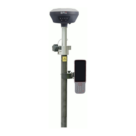
EFIX CM3 User manual

Preface
The purpose of this book
This article is a user manual for the Shanghai-based CM3 series, which is the instruction
manual.
Introduction to this book
This user guide describes in detail how to install, configure, and use the CM3 series, and the
language style in this article is simple, easy to understand, and the process of describing the
operation is clear and simplistic so that beginners can learn to use all aspects of operation easily,
quickly and accurately。
Experience requirements
In order to make better use of the CM3 series, EFIX suggests that you read this user guide
carefully before using this product. If you do not know much about the principles of the CM3
series, please contact us for technical advice and training.
Exemption of liability
Before using this product, please be sure to read the user guide carefully in order to make
better use of this product.Shanghai EFIX Geomatics Co., Ltd will not be liable for any losses
caused by the failure to act in accordance with the requirements of this article, or to correctly
understand the requirements of this article, but we are committed to continuously improving
product functionality and performance, improving the quality of service, and reserve the right to
change, optimize and improve the contents of the instruction manual, and regularly update the

content in the form of upgrades, so please pay attention to our official website
(www.efix-geo.com) The latest release information.
Technology and services
The message board section has been opened on the website, if you have questions can be
left through the "message board", or directly call the technical consultation phone:400-602-8152,
we will answer your questions in a timely manner.
Relevant information
You can find the manual in the following ways:
1, EFIX GNSS products, the instrument box will be accompanied by a product instruction
manual, convenient for you to operate the instrument.
2, the official website of the login http://www.efix-geo.com, in the "action video" column
can download to watch the video operation instructions.
Your suggestion
If you have any suggestions and comments on this manual, please visit the official website of
the far, in the "message board" section message, your feedback information on the quality of our
manual will be greatly improved.

Preface ..............................................................................................................................................2
The purpose of this book ..................................................................................................................2
Introduction to this book ..................................................................................................................2
Experience requirements..................................................................................................................2
Exemption of liability ........................................................................................................................2
Technology and services....................................................................................................................3
Relevant information ........................................................................................................................3
Your suggestion .................................................................................................................................3
Safety Directions ...............................................................................................................................5
Get started with the CM3 series (quick start). ..................................................................................6
1.1 Connecting the instrument ........................................................................................................6
1.2 Set the base - the external base.................................................................................................6
1.3Set up the rover...........................................................................................................................6
1.4 Create a new project ..................................................................................................................6
1.5 Sitecalibration.............................................................................................................................6
1 Product introduction......................................................................................................................8
1.1 The appearance of the receiver ..........................................................................................8
1.2 Lower shell ..........................................................................................................................8
1.3 The instrument is taken in high quantities..........................................................................9
2 Receiver field work requirements ..................................................................................................9
2.1 FL3 radio settings ..............................................................................................................10
3 PC-side web page Set up receiver instructions ............................................................................12
4 Smart phone-side web page Set up receiver instructions............................................................17
5 Operation and accuracy of static operating mode.......................................................................20
5.1 Static measurement job steps...........................................................................................20
5.2 Static web page parameter settings..................................................................................21
5.3 Data download ..................................................................................................................22
5.4 Static accuracy test............................................................................................................23
6 RTK setup method and tilt measurement....................................................................................24
6.1 CORS login settings............................................................................................................24
6.2 Radio send and receive settings........................................................................................24
6.3 Real-time dynamic RTK accuracy.......................................................................................24
6.4 Tilt measurement initialization method............................................................................24
7 Firmware upgrade method ..........................................................................................................26
7.1 Upgrade via web page.......................................................................................................26
7.2 Upgrade via USB stick........................................................................................................26
7.3 The data line (mnt directory) upgrade ..............................................................................27
Appendix 1 use and precautions....................................................................................................28
Appendix 2 of the main technical indicators.................................................................................29
Get technical support......................................................................................................................31

Safety Directions
The following directions enable the person responsible for the product, and the person who
actually uses the equipment, to anticipate and avoid operational hazards.
The person responsible for the product must ensure that all users understand these
directions and adhere to them.
The product must not be disposed with household waste. Dispose of
the product appropriately in accordance with the national regulations in
force in your country. Always prevent access to the product by
unauthorized personnel.
FCC ID:2A3MU-CM3
FCC Statement, Applicable in U.S.
1) FCC 15.19
This device complies with part 15 of the FCC Rules. Operation is subject to
the following two conditions:
(1) This device may not cause harmful interference, and (2) this device
must accept any interference received, including interference that may
cause undesired operation.
2)FCC 15.21
Warning: Changes or modifications to this unit not expressly approved by
the part responsible for compliance could void the user’s authority to
operate the equipment.
3) FCC 15.105
For a Class B digital device or peripheral, the instructions furnished the
user shall include the following or similar statement, placed in a prominent
location in the text of the manual:
Note: This equipment has been tested and found to comply with the limits
for a Class B digital device, pursuant to part 15 of the FCC Rules. These
limits are designed to provide reasonable protection against harmful
interference in a residential installation. This equipment generates uses
and can radiate radio frequency energy and, if not installed and used in
accordance with the instructions, may cause harmful interference to radio
communications. However, there is no guarantee that interference will not
occur in a particular installation. If this equipment does cause harmful
interference to radio or television reception, which can be determined by
turning the equipment off and on, the user is encouraged to try to correct
the interference by one or more of the following measures:
—Reorient or relocate the receiving antenna.
—Increase the separation between the equipment and receiver.
—Connect the equipment into an outlet on a circuit different from that to
which the receiver is connected.
—Consult the dealer or an experienced radio/TV technician for help.
4)FCC RF Exposure
This equipment complies with FCC radiation exposure limits set forth for an
uncontrolled environment.
This equipment should be installed and operated with minimum distance
20cm between the radiator & your body.

Get started with the CM3 series (quick start).
Quick starts with a fixed solution using the CM-Survey software to set up the external station
1-N mode. The previous instrument installation is detailed in Chapter 3 Receiver Field Work
Requirements.
1.1 Connecting the instrument
The CM3 series uses WiFi or Bluetooth to connect instruments.
Connect CM3 Series receivers
When the CM-Survey software is turned on after the host is turned on, click Connect
Instrument to enter the Connect instrument interface and connect the SN number of the CM3
Series receiver using Bluetooth/WiFi (Bluetooth password:1234) , click Connection,
CM-Survey will prompt "Connection succeeded" when the connection is successful.
1.2 Set the base - the external base
Connect to the base, turn on FL3 Radio Search CM3 Bluetooth for a configured connection,
and set to CM3 external work mode.
1.3Set up the rover
Connect the rover, enter the Instrument Settings interface, click on rover, new station
working mode: configuration protocol, channel, Baud rate, save and apply this working mode
successfully, the rover settings are completed.
1.4 Create a new project
Regardless of the job mode, you must first create a new project to manage the data. Enter
Project Management, click New, enter the project name, creator, select the creation time and
time zone, use or create new coordinate system parameters, click OK, that is, complete the new
project.
1.5 Sitecalibration
The first time you go to a measurement area, you need to dositecalibration to match the
known point coordinates.
(1) Enter known point coordinates: Data Management → Point Management→ Add.
(2) Field measurement control points (if the longitude and latitude coordinates of the
control points are known, enter the longitude and latitude coordinates in the Data Management
→Point Management→ Add).
Note: (1) (2) order can be reversed.
(3) Select the coordinate system in the Coordinate System → Coordinate Parameters and
enter the correct central meridian (if there is a projected high input projection height).
(4) Enter the Coordinate System→ the → add, the GNSS point selects the measured
coordinates (or the latitude and longitude of the input), and the known points select the input
plane coordinates (NEH). If both the known point plane and elevation are used, select the
"horizontal and vertical" correction in the usage mode, the Horizontal correction if only plane
coordinates are used, and if only elevation coordinates are used, select the Vertical correction,
and select all control points in turn.
(5) Click on "Calculation" in the "Coordinate System" → "Conversion Parameters" interface,

if the residuals are small, indicating that the correction is qualified, click on "Application" and
select "Yes" in the pop-up prompt.
Note: (1) Known points are best distributed at the edges of the entire job area, for example,
if point correction is done with four points, the measuring job area is best inside the quads
connected to the four points.
(2) Be sure to avoid the linear distribution of elevation control points, for example, if you use
three elevation points for point correction, the triangle composed of these three points should be
as close as possible to the positive triangle, if it is four points, as close as possible to the square,
we must avoid all known points of distribution close to a straight line, which will seriously affect
the accuracy of the measurement.
Once the point correction is complete, you can start measuring/lofting and so on. Only the
first job in the same project requires point correction, and subsequent jobs require only a single
control point base station translation.
Its physical operation can be found in the CM-Survey software operation video, which is
available next Path: http://www.efix-geo.com download in the Action Videos column.

1 Product introduction
1.1 The appearance of the receiver
CM3 Figure:
Detailed description of the indicator
The CM3 indicators above are: differential data indicator, power indicator.
Indicator
Color
Meaning
①Differential
data indicator
Yellow
In base mode, the color is yellow
Yellow
Green
When the mobile station receives the differential data, the
single point or float is yellow
The mobile station receives differential data fixed and green
②Power
Indicator
Red
Red in normal power-on use
Yellow
Yellow in the shutdown and power-on charging state
Detailed description of the button
Button
Meaning
②Power button
Press and hold 3s to shut down or shut down
The shutdown state is charged as a red light constant and as a green light
constant when fully charged
1.2 Lower shell
The lower shell is mainly contained
Type-C interface: you can use the Type-Cdata line to download static data, USB drive upgrade firmware;
TNC interface: connecting rod antennas;
Main nameplate: includes instrument model, SNnumber, PNnumber, etc.
①
②

1.3 The instrument is taken in high quantities
Using the auxiliary height gauge, the bottom of the antenna is selected by means of measurement
2 Receiver field work requirements
Precautions:
1. The distance between the station mode, the base station scaffold and the station whip antenna
scaffold is recommended to > more than3mto avoid interference with satellite signals by radio stations.
2. The reference station should be located in a higher terrain, open field of view, to avoid
high-voltage lines, transformers and other strong magnetic fields, in order to facilitate the transmission of
UHFwireless signals and satellite signal reception, network mode also need to pay attention to the operator
network coverage of hypothetical points.
1. Radio mode, if the mobile station is far away, also need to add a radio antenna lengthener.
2. If the reference station is mounted on a known point, to do a strict alignment.
3. The connection between the power cord and the battery should be red, black and negative to
avoid short circuits.
4. When the station is working, make sure to connect the external antenna, otherwise long hours
will cause the sending signal to be absorbed by the station itself and burn the station.
5. When connecting cables, note the connection of LEMOhead red dots to red dots.
6. Working in GPRSmode,GPRS traffic per hour is around 0.5M-1.5M(related to the number of
satellites and network environment).
The illustration of the installation of the external radio station of the base station is as follows:
Auxiliary Height Gauge

(1) Whip antenna(2)Radio antenna connection base(3)Extend rod(4)aluminum disc
(5) Scaffolding(6)FL3Radio(7) Radio Power Cord(8)Battery
(9) Host(10) Auxiliary Gauge(11)Base
2.1 FL3 radio settings
In external station job mode, use the radio panel to turn on the key to open the station, and use the left and
right switch keys and up and down keys to configure the station.
See FL3 external radio instructions
Note: Each channel corresponds to a unique frequency, which can be set by the remote radio write-up
software.
Transparent
0
Arbitrarily writable
1
411.050
17
465.550
33
443.000
2
412.050
18
467.550
34
444.000
3
413.050
19
469.550
35
445.000
4
414.050
20
451.550
36
446.000
5
415.050
21
445.013
37
447.000
6
416.050
22
445.025
38
448.000
7
417.050
23
445.038
39
449.000
8
418.050
24
445.050
40
450.000
①
②
③
④
⑤
⑥
⑦
⑨
⑩
⑩
错误
①
⑧
⑨

9
419.050
25
445.063
41
438.125
10
410.050
26
445.075
42
440.125
11
453.550
27
445.088
43
441.125
12
455.550
28
445.100
44
442.125
13
457.550
29
445.113
45
443.125
14
459.550
30
445.000
46
444.125
15
461.550
31
441.000
47
446.125
16
463.550
32
442.000
48
447.125
TT450s
0
Arbitrarily writable
1
411.050
17
465.550
33
443.000
2
412.050
18
467.550
34
444.000
3
413.050
19
469.550
35
445.000
4
414.050
20
451.550
36
446.000
5
415.050
21
445.013
37
447.000
6
416.050
22
445.025
38
448.000
7
417.050
23
445.038
39
449.000
8
418.050
24
445.050
40
450.000
9
419.050
25
445.063
41
438.125
10
410.050
26
445.075
42
440.125
11
453.550
27
445.088
43
441.125
12
455.550
28
445.100
44
442.125
13
457.550
29
445.113
45
443.125
14
459.550
30
445.000
46
444.125
15
461.550
31
441.000
47
446.125
16
463.550
32
442.000
48
447.125
In the menu bar, you can set up communication protocols, including the Transparent and TT450s protocols.
Through the left and right key switching protocol, channel, Baud rate, transmit power interface, through the
upper and lower key switching different protocols, different channels, different baud rate, different transmit
power, power key determination settings and configuration completed.
When the base station starts successfully (i.e. the base station differential data lamp 1s flashes once) and the
connection is normal, the radio transmitter flashes once a second, indicating that the data is transmitting
normally.
note
Once the transmission station channel of the reference station is modified, the mobile station also needs to
be modified to the corresponding channel, otherwise the differential signal cannot be received, only the same
channel can work properly!

3 PC-side web page Set up receiver instructions
The process
of operation
Detailed description
Note
1.Login the
web page
First step:turn on
receiver WiFi,Search for
receivers on your
computer or other
WiFi-enabled device;
Default name: Receiver SNnumber
Second step:open google
chrome browser, Enter
the website 192.168.1.1
to enter the login
interface;
Default user name: admin
Default password: password
2.Receiver
status
Click the "Receiver
Status" on the left side of
the page. You can check:
[The receiver
position]
[Receiver activity]
[Google Map]
The receiver position interface shows the
longitude and latitude of the receiver's current
phase center, dop value, the satellite used, the
satellite tracked, and the receiver clock.
The receiver activity interface can view satellite
information tracked by the receiver, current UTC
time, receiver runtime since power-on, internal
storage and available storage, battery power,
whether to connect to external power supply.
Google Map shows the current location in Google
Map.
3.Satellites
Click the "Satellites" on
the left side of the page.
You can check:
[Satellite tracking
table]
[Satellite tracking
map]
[Star chart]
[Satellite settings]
[Satellite tracking table]You can see the satellites
tracked by the receiver, displaying information
about each satellite tracked in the form of a list,
including satellite number, satellite type, altitude
angle, adhesion angle, L1 signal-to-noise ratio, L2
signal-to-noise ratio, L5 signal-to-noise ratio, B1C
signal-to-noise ratio, B2A signal-to-noise ratio,
and whether to use it.
[Satellite tracking map]You can view satellite
information as an icon, and you can check the
type of satellite you want to view and the
signal-to-noise ratio to see the information.
[Star chart]Displays a satellite type map.
[Satellite settings]Satellite systems can be enabled
or disabled.
4.Receiver
Click the "Receiver
[Summary]View GNSS receiver information and

configuration
configuration" on the left
side of the page. You can
check:
[Summary]
[Antenna
parameter
settings]
[Reference station
settings]
[Receiver reset]
[Language
switching]
[Account
management]
[HCPPP settings]
reference station information.
[Antenna parameter settings]Antenna parameter
settings can be set antenna quantity, antenna
manufacturer, antenna type, antenna number,
antenna height, height cut-off angle, PDOPlimits.
[Reference station settings] You can set the
reference station's manual start base station,
self-starting base station, self-start mobile station
mode, you can set the reference station
coordinates, support sampling average.
Note: There are several input methods for the
location of the reference station. You can click to
get the current position to set the reference
station location, this method of reference station
coordinates because it is measured in a single
point state of an antenna phase center
coordinates, not very accurate;
Sampling average, positioning limit is divided into
a single point and fixed, single point refers to a
single point of state can collect reference value
coordinate data; Collecting a number means
collecting so many points in total, and then taking
the average and automatically filling in the
incoming reference station location column. The
progress bar represents the percentage value of
the total number of collected coordinates.
Coordinate offset threshold, which sets the
difference between the current latitude and
longitude coordinates obtained by the base
station mode and the longitude and latitude
coordinates in the base station list.
Base station list, you can set up several fixed base
station location of the longitude and latitude
coordinates as a list of typing, when set up since
the start of the base station after the receiver
automatically match the nearest latitude and
longitude coordinates to start sending differential
data.
Click Save to save your current settings.
[Receiver reset] The receiver can be shut down,
restarted, satellite data cleared, and the
appearance settings restored. Restarting the
receiver means restarting the receiver, clearing
the satellite data refers to clearing the satellite

data found by the receiver, restoring the factory
settings refers to clearing the receiver and
reverting to the factory configuration, and turning
off the receiver means to turn off the receiver.
[Account management]Interface language
switching is supported。
[Account management] Accounts can be added,
saved, deleted, and passwords modified;
[HCPPP settings]Select the HCPPPcalendar time in
the drop-down box.
5.Data
recording
Click the "Data
recording" on the left
side of the page. You can
check:
[Recording
settings]
[FTP push
settings]
[FTP push records]
[Data download]
[Recording settings] If automatic recording is
enabled, static data is recorded as soon as the
receiver is turned on and satellite single point
positioning is found. Storage is divided into
internal storage and external storage, internal
storage refers to the receiver's own storage
capacity, the specific value is seen in the receiver,
external storage refers to the inserted mobile
hard disk, the total capacity and available capacity
depends on the hard disk.
Note: [Recording settings]
Whether to turn on --- thread on
Sample intervals --- 1Hz to 60s are optional
The height cut-off angle --- filled in from 0 to 90
degrees
The recording duration --- 0 to 1440 minutes
Site name --- This site name
Antenna height --- fill in the antenna height
Measure --- can be selected at phase center, high,
oblique high school
RINEX Storage --- off,3.0x,2.11 selected
The start time --- timed start storage
Whether the start time is enabled --- Yes/No
button represents whether the previous option
start time is, yes, start recording at the set time,
or start immediately.
Loop storage --- automatically overwrites thread
early data after the set storage space exceeds.
Single acquisition --- whether to store once
according to the set duration
Storage location --- optional internal and external
memory
Storage space --- reserves memory space for
threads

ftp push -- You can set ftp push to turn off
[FTP push settings]You can set up 3 FTP servers,
click to modify the pop-up FTP push settings
window can set the server IP, port, remote
directory, local push directory, server description,
username, password. FTP push can set up the FTP
server to be pushed, otherwise select Off.
[FTP push records]A list of realistic FTP push
records.
[Data download]
6.IO settings
Click the “IOSettings” on
the left side of the page
[RTK client] Connection protocols include NTRIP,
APIS_ROVER, which support CORS and handbook
network mobile stations, respectively.
Under the NTRIP protocol, CORS can be logged in
by setting the IP, port, source list, username,
password.
under the APIS_ROVER protocol, you can log on to
the remote network server and use it as a mobile
station for the network RTK.
[TCP/UDP_Client/Ntrip Serve]
1、[TCP/UDP_Client/Ntrip Serv] The protocol is
optional for TCP,UDP,NTRIP1,NTRIP2 protocols.
2、A "remote IP" is the address and port number
of a PC received at the remote end, which is the
destination address of the receiving terminal.
3、The data send port can be set up in the port
number.
4、Differential data, raw data, astrological
data,HCPPPdata,HRCdata,GPGGA,GPGSV,GPRMC,
GPZDA,GPGST,GPVTG,GPGSA,GPPOS are the
machine support output data types, can be set
whether the output and the output frequency.
5、After setting the parameters, click "OK" at the
bottom of the page to save the current settings,
data entries cannot be edited during data
sending, details can be viewed under the detailed
button.
[TCP/serve/Ntrip caster] The Ntrip protocol and
the TCP protocol are supported in the connection
protocol, and the Ntrip protocol allows the user to
log directly into the CM3 series to obtain data.
[Serial Port] Data output Baud Rate, Differential
Data,RawData,HCPPPData,HRCData,GPGGA,GPGS
V,GPRMC,GPZDA,GPGST,GPVTG,GPGSA,GPPOS are

the machine support output data types, can be
set whether the output and output frequency. If
differential data needs to be output, it needs to
be set to self-starting base station mode, with an
external radio station typically with a Baud rate of
9600.
[Bluetooth] Data output Baud Rate, Differential
Data,RawData,HCPPPData,HRCData,GPGGA,GPGS
V,GPRMC,GPZDA,GPGST,GPVTG,GPGSA,respective
ly, the machine supports the output data type,
can be set whether the output and the output
frequency. If travel sub-data is required, it needs
to be set to self-starting base station mode.
[Radio] The differential data format of the built-in
radio transmission and the data forwarding
switch, sending differential data, need to be set to
the self-starting base station mode, the radio
module must be turned on power-up, set power
and frequency, etc.
7.Network
settings
Click the "Mobile
network" on the left side
of the page. You can
check:
[Mail alarm]
[HTTP]
[HTTPS]
[FTP service]
[Mail alarm]Contains three things: recipient
information, sender information, and message
alarm settings. Recipient information can be filled
in 1-3recipients, sender information, including
account number, password, and server address,
email alarm settings for receiver power-on mail
alarm, external power interruption mail alarm,
low battery level mail alarm, FTPpush failure mail
alarm, registration code expired or about to
expire (7 days in advance) mail alarm options
checked.
[HTTP]HTTP ports can be set to 80 by default and
not modified.
[HTTPS]HTTP channels are security-targeted, and
sensitive industry customers need to use this
feature to transfer data, set enable or port.
[FTP service] Set up a username and password。
8.Module
settings
Click the "WiFi network"
on the left side of the
page. You can check:
[Summary]
[WiFi settings]
[Bluetooth
settings]
[Radio settings]
[Summary] Contains WiFi and radio information.
WiFi information shows power status, WiFi mode,
MAC address, SSID, and radio information
includes station type, station power, air baud rate,
radio frequency, radio protocol, radio band,
frequency range.
[WiFi settings]Set WiFion, power on
automatically, WiFimode, SSID.

[Bluetooth settings]Includes local name,
MACaddress, PINcode, default 1234(do not
modify, this will invalidatethe NFCfunction).
[Radio settings] Set the station status, power on
whether to start, radio protocol, station step
value, air baud rate, radio power, radio frequency,
etc. , if you simply use the web page settings,
want to use the radio function to turn the radio
state on, power on self-start, IOsettings of the
station if need to use, the premise is also must
turn on the station, set the corresponding
frequency, power and so on.
12.Firmware
Click the "Firmware " on
the left side of the page.
You can check:
[Firmware
information]
[Hardware
version]
[Profile]
[System logs]
[User log]
[Firmware
upgrade]
[Board upgrade]
[Receiver
registration]
[Firmware information]Displays the current
firmware version of the firmware, the firmware
release date.
[Hardware version]For developers to learn about
receiver hardware.
[Profile] The current settings for the receiver can
be saved as a profile download, or a saved profile
can be mounted.
[System logs] You can download the system
software run logs for easy problem analysis by
developers.
[User log] You can set the date and time of the
receiver power-on, the time of external power
disconnect, the time of completion of Search Star,
and so on.
[Firmware upgrade] Web firmware upgrade,
please refer to the details [CM3 Series firmware
upgrade method].
[Board upgrade] Select the board firmware to
upgrade the board.
[Receiver registration]Implements the function of
registering the receiver.
4 Smart phone-side web page Set up receiver instructions
The process
of operation
Detailed description
Note
1.Login
webpage with
your smart
First step: turn on the
receiver WiFi, use the
mobile phone wireless
Default name: Receiver SN number

phone
search and connect to the
receiver;
Second step: open the
smart phone browser,
enter the remote address
192.168.1.1 in the address
bar, enter the login
interface;
Default username: admin
Default password: password
2. Receiver
status
Click the "Receiver Status"
on the left side of the page.
You can check:
[The receiver
position]
[Receiver activity]
[The receiver position]The interface shows the
longitude and latitude of the receiver's current phase
center, the DOP value, the satellite used, the satellite
tracked, and the receiver clock.
[Receiver activity] You can view the satellite
information tracked by the receiver, the current UTC
time, the receiver runtime since power-on, internal
storage and available storage, external storage,
whether to access external power supply, battery
power.
3.Satellites
Click the "Satellites" on the
left side of the page. You
can check:
[Satellite tracking]
[Satellite settings]
[Satellite tracking]Contains a list of stars and
satellites. Satellite distribution can be seen in the star
map, and satellite tracking information can be seen
below the satellite tracking GPS satellite, GLONASS
satellite, BDS satellite, GALILEO satellite and QZSS
satellite.
[Satellite settings]You can enable or disable a single
satellite by clicking the button.
4.RTK work
mode
Click the "RTK work mode"
on the left side of the page.
[RTK work mode]
Base external radio work mode
Base network mode
Rover network mode
Rover Ntrip work mode
Rover radio work mode
Base combination
5.Data
recording
Click the "Data recording"
on the left side of the page.
[Datarecording]The total state of the data record can
be turned on or off for the entire data record. If
automatic recording is enabled, static data is
recorded as soon as the receiver is turned on and
satellite single point positioning is found. Sample
interval, height cut-off, record duration, site name,
antenna height setting, method of extraction, RINEX
storage can also be advanced: start recording date,
time, point storage, loop storage, single acquisition,
storage location, storage space, observer, FTP push
or not.

6.IO settings
Click the "IO setting" on the
left side of the page.
[RTK client]Connection protocols include NTRIP,
APIS_ROVER, which support CORS and handbook
network rover stations, respectively.
Under the NTRIP protocol, CORS can be logged in by
setting the IP, port, source list, username, password.
under the APIS_ROVER protocol, you can log on to
the remote network server and use it as a mobile
station for the network RTK.
[TCP/UDP_Client/Ntrip Serve]
1、[TCP/UDP_Client/Ntrip Serve]The protocol is
optional for TCP,UDP,NTRIP1,NTRIP2protocols.
2、A "remote IP" is the address and port number of a
PC received at the remote end, which is the
destination address of the receiving terminal.
3、The data send port can be set up in the port
number.
4、Differential data, raw data, astrological
data,HCPPPdata,HRCdata,GPGGA,GPGSV,GPRMC,GPZ
DA,GPGST,GPVTG,GPGSA,GPPOSare the machine
support output data types, can be set whether the
output and the output frequency.
5、After setting the parameters, click "OK" at the
bottom of the page to save the current settings, data
entries cannot be edited during data sending, details
can be viewed under the detailed button.
[TCP/serve/Ntrip caster] The Ntrip protocol and the
TCP protocol are supported in the connection
protocol, and the Ntrip protocol allows the user to
log directly into the CM3 series to obtain data.
[Serial Ports] Data output Baud Rate, Differential
Data,RawData,HCPPPData,HRCData,GPGGA,GPGSV,G
PRMC,GPZDA,GPGST,GPVTG,GPGSA,GPPOSare the
machine support output data types, can be set
whether the output and output frequency. If
differential data needs to be output, it needs to be
set to self-starting base station mode, with an
external radio station typically with a Baud rate of
9600.
[Bluetooth] Data output Baud Rate, Differential
Data,RawData,HCPPPData,HRCData,GPGGA,GPGSV,G
PRMC,GPZDA,GPGST,GPVTG,GPGSA,respectively, the
machine supports the output data type, can be set
whether the output and the output frequency. If
travel sub-data is required, it needs to be set to

self-starting base station mode.
[Radio] The differential data format of the built-in
radio transmission and the data forwarding switch,
sending differential data, need to be set to the
self-starting base station mode, the radio module
must be turned on power-up, set power and
frequency, etc.
8.Module
Click the "Module" on the
left side of the page. You
can check:
[WiFi settings]
[Bluetooth settings]
[WiFi settings] Set power status, power-on start-up,
WIFI mode, SSID, MAC.
[Bluetooth settings] The local name, MAC address,
PIN, discoverable status is displayed in the summary;
9.Firmware
Click the "Firmware" on the
left side of the page. You
can check:
[Firmware
information]
[Firmware upgrade]
[Hardware
information]
[Firmware information] Displays the current
firmware version of the firmware, the firmware
release date.
[Firmware upgrade] Web firmware upgrade, please
refer to the details [CM3 series firmware upgrade
method].
[Hardware information] For developers to
understand the receiver hardware information,
including motherboard, core board, PN, SN, board
firmware version number.
9.Other
settings
Click the "Firmware" on the
left side of the page. You
can check:
[Receiver
registration]
[Language
switching]
[Network services]
[Account
management]
[Receiver registration] Implements the function of
registering the receiver.
[Language switching] You can switch the web
language.
[Network services] Including FTP service and HTTP
two settings, FTP service can be set to the machine
FTP storage username password, HTTP port number,
default 80, do not modify。
[Account management] Set your username,
password, and change your password.
5 Operation and accuracy of static operating mode
5.1 Static measurement job steps
Step1Set up the instrument
The instrument is placed on the measuring point, the height is moderate, the scaffold is solid, and the level is
strictly aligned to the middle.
Step2Measures antenna height
Table of contents
Other EFIX Receiver manuals

