EFT BYD Battery-Box HV Series Instruction Manual

BYD Battery-Box HV
Service Guideline from EFT-Systems
Version 2.0
Valid for H 5.1 / 6.4 / 7.7 / 9.0 / 10.2 / 11.5
Important: The installation and all other kinds of works or measurements in combination with the Battery-Box
HV are only allowed by professional and qualified electricians.
This manual is a shortened assistance for the installation of the Battery-Box High Voltage and does not replace
the original manual, which can be found on www.eft-systems.de or www.byd.com. The installation must be
carried out by a trained and qualified electrician. Attention: High Voltage! Improper handling can cause danger
and damage.

CONTENT
CONTENT 2
1. CHECK INSTALLATION 3
2. ERROR ANALYSIS 4
2.1 BCU can not be switched on 4
2.2 BCU system switch falls after a few seconds 4
2.3 Current Alarm: BatteryCommErr 4
2.4 Current Alarm: MonitorCommErr 4
2.5 Communication problem 5
2.6 Current Alarm: BatteryDiff 5
2.7 Current Alarm: UT / OT (e.g Cell_UT) / SysTemp 6
2.8 Current Alarm: Cell_UV1 / Cell_UV2 / Cell_UV3 6
2.9 Current Alarm: DCBusFault 6
2.10 Voltage measurement 7
2.11 Visual Check 8
2.12 Identifying a faulty module (Variant 1) 8
2.13 Identifying a faulty module (Variant 2) 9
3. SERVICE TASKS 10
3.1 BCU replacement 10
3.2 Module Replacement 10
3.3 Charging with external HV charger 10
4. SERVICE CONTACT 11
2

1. CHECK INSTALLATION
Please proceed first with the installation steps by:
No.
Name
Description
0
Inverter installed
correctly?
Please make sure that the connection between the Battery-Box and the inverter
and the installation of the inverter have been carried out correctly. If in doubt,
follow the instructions of the inverter manufacturer.
IMPORTANT: Please install the latest software on the inverter.
1
Configuration
SMA: 4 -8 Battery modules
KOSTAL: 4-9 Battery modules
FRONIUS: 5-9 Battery modules
GOODWE: 4-9 Battery modules
INGETEAM: 4-5 Battery modules
2
DC Power Cable
Make sure that + and - are properly connected.
Check the imprint and the board!
3
Communication cables
Please check:
- CAT5 or higher;
- check the cables and replace them if necessary
- remove not necessary jumpers (see step 20)
4
Grounding
Battery-Box connected directly to the ground-bus of the house.
The battery must not be earthed via the inverter! Otherwise, communication
problems are possible. Correct grounding is absolutely necessary!
5
Installation in the Web
Interface
- Installation Config: Number of Modules + Inverter Manufacturer
- Update: install the latest released software (www.eft-systems.de)
6
State of charge (SOC)
When installed for the first time, the battery will show a predefined SOC of 19%.
This does not correspond to the actual SOC and the battery corrects th eSOC at
the first full charge or discharge. The actual SOC of new modules is about 35%.
Therefore, only perform a module extension if the battery system is close to 35%
SOC. For details see the extension manual (www.eft-systems.de/downloads).
7
Connect to the Internet
(recommended)
Connect the battery to the Internet using an Ethernet cable.
8
Checking the correct
operation
The system runs properly if:
- Home shows RUN and Current Alarm shows no entries
- No error messages on the inverter
- Inverter displays voltage and battery charge correctly
- System charges / discharges
9
Web interface:
Error description
If there are any errors in the section Current Alarm, please follow the instructions
on the following pages.
10
IMPORTANT: If you can not complete the commissioning, then turn off the battery via the system switch on
the BCU before you leave the site.
3

2. ERROR ANALYSIS
Please refer to the general steps before proceeding, see chapter 1.
2.1 BCU can not be switched on
No reaction, LEDs on the BCU board do not light up, although the system switch is switched on.
No.
Name
Description
11
Voltage measurement
Please measure the voltage as shown in step 2.10 .
12
Visual check
See step 2.11
13
BCU exchange
Only if voltage and visual examination look good:
Test another BCU, if available.
2.2 BCU system switch falls after a few seconds
Battery does not stay on for more than 30 seconds. Therefore you can not enter the web interface to read the event codes.
No.
Name
Description
14
Voltage measurement
Please measure the voltage as shown in step 2.10 .
15
Check the individual
modules (variant 2)
See step 2.13
2.3 Current Alarm: BatteryCommErr
Error probably caused by a communication failure between two modules or within a module.
No.
Name
Description
16
Visual check
See step 2.11
17
Check the individual
modules (variant 2)
See step 2.12
2.4 Current Alarm: MonitorCommErr
Error probably caused by the battery module on top or the BCU.
No.
Name
Description
18
Visual check
See step 2.11
19
Check BCU and top
module
Remove the top module from the tower.
- If the "MonitorCommError" error is no longer displayed in Current Alarm , the
topmost module may be faulty. If available, exchange the module with another
one.
- If the error "MonitorCommError" continues to be displayed, the error could be
due to the BCU. If available, exchange the BCU as a test.
4

2.5 Communication problem
Inverter reports communication problem
Battery-Box System State under Home shows STANDBY / IDLE
Current Alarm: InverterCommError
No.
Name
Description
20
Jumper
See short instructions - please check:
SMA: only jumper JP1
KOSTAL: only jumper JP2
FRONIUS: leave both jumpers (except for variant 2, see quick guide)
GOODWE: leave both jumpers connected
21
Grounding
Connected Battery-Box directly to the ground-bus of the house. Only with a correct
grounding of the battery, a trouble-free and secure data transmission can be
guaranteed. The battery must not be earthed via the inverter! Otherwise,
communication problems are possible. Correct grounding is absolutely
necessary!
22
Communication cable
Replace the communication cable (min. CAT5!)
23
Use other communication
port (J5 instead of J2)
The BCU has two identical communication ports, labeled J2 and J5. The short
guide show the wiring at J2. If there are any communication problems, try to
connect the PINs to J5 instead.
24
Disconnect from the
network
Please check the local network and completely disconnect the system from the
network in order to exclude communication interference caused by switches or
WLAN repeaters (multicasting).
25
Restart the entire system
Generally:
- Switch off: Battery off > Inverter off
- wait at least 10 minutes!
- Switch on: inverter on > battery on
Kostal (the order is important):
- unplug Ethernet cable from inverter
- turn off the system: battery off > inverter DC switch off > AC off > unplug PV
strings
- wait at least 10 minutes
- turn on system: plug in PV strings > AC on > inverter DC switch on > battery on
- connect Ethernet cable once system is running again
2.6 Current Alarm: BatteryDiff
Error probably caused by a faulty battery extension.
No.
Name
Description
26
Battery recently
extended?
(new modules added)
If the battery system has recently been extended:
Remove the new modules from the system and follow the instruction on how to
correctly extend the system (see extension manual)
If no module extension has taken place and all modules have been installed at the
same time, please contact EFT-Systems. Please make a screenshot of the section
RUN Data on the web interface.
5

2.7 Current Alarm: UT / OT (e.g Cell_UT) / SysTemp
System has detected a temperature which is too high (>50°C) or too low (<-10°C).
No.
Name
Description
27
SysTemp
If SysTemp in Run Data is OK (-10°C to +50°C):
Test another BCU, if available
28
Charge_UT / OT
Cell_UT / OT
If maxCellTemp or minCellTemp is outside the range -10°C to +50°C: Check
temperatures under Run Data for each module. If only one module deviates, then
try to remove this module or replace ist, if a replacement module is available.
2.8 Current Alarm: Cell_UV1 / Cell_UV2 / Cell_UV3
Error Probably caused by undervoltage or a faulty sensor.
No.
Name
Description
29
UV1
Recharge of the battery by the inverter is necessary. Please go through the above
steps (especially: check communication, install updates, restart the entire system).
If not recharge by inverter is not possible, a charger may be required. Switch off
the battery and contact EFT-Systems (screenshots).
30
UV2
If the battery is not being charged by the inverter immediately after restarting, then
switch off the battery after a few minutes and contact EFT-Systems (screenshots,
voltage). Charger necessary.
31
UV3
Immediately turn off the battery and contact EFT-Systems.
2.9 Current Alarm: DCBusFault
No.
Name
Description
32
DC Power cables
Make sure that + and - are properly connected.
Check the imprint and the board!
33
Disconnect the battery
from the inverter
For testing, please disconnect the inverter completely from the battery
(communication cable and DC cable). If the error persists, then try another BCU, if
available.
6
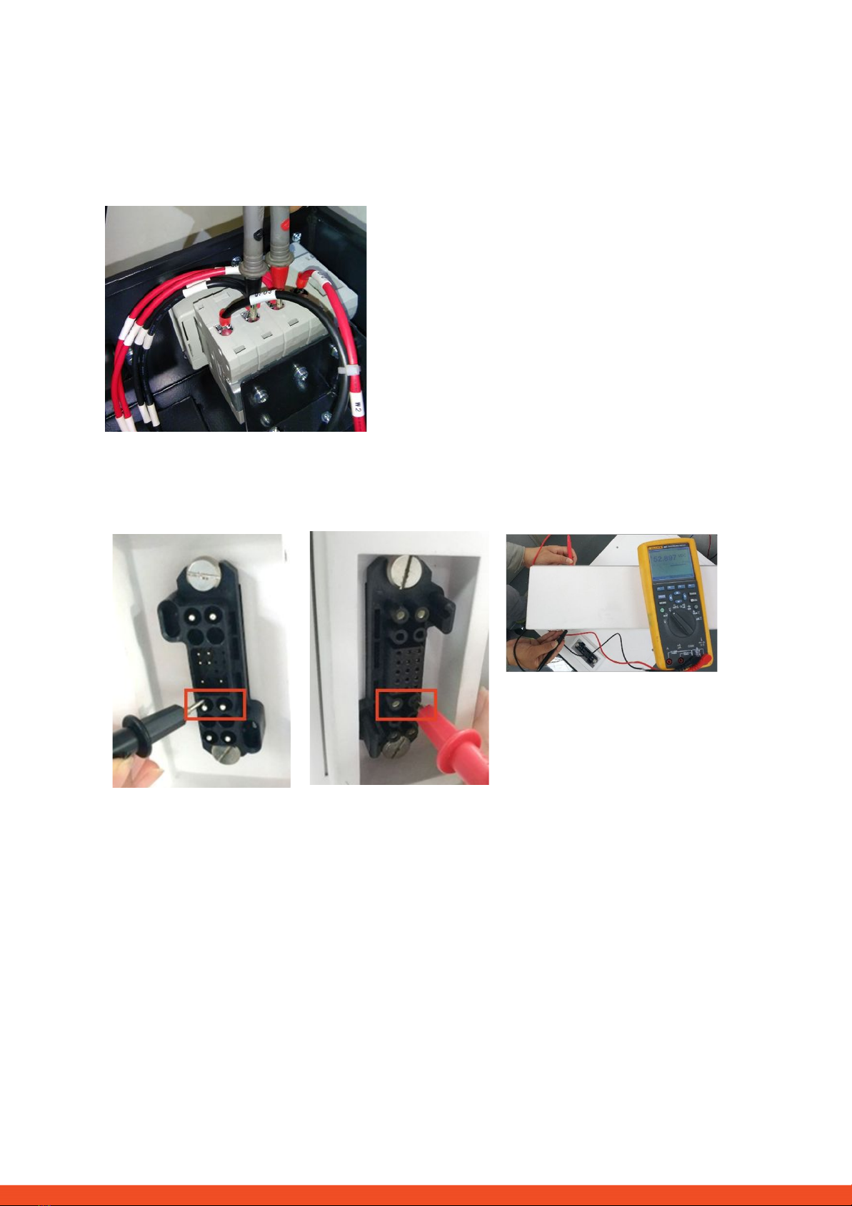
2.10 Voltage measurement
ATTENTION: High voltage!
The nominal voltage is obtained by multiplying the number of modules by 50V. Nominal system voltage should
therefore be in the range 200V-450V.
If the measured voltage deviates significantly from the nominal value, please check the electrical voltage at the
individual modules, as shown below:
Positive
Negative
Measurement:
7
2.11 Visual Check
The PINs should not be bent or touch each other. Otherwise, a short circuit with a damage to the BCU is possible.
Correct
defect
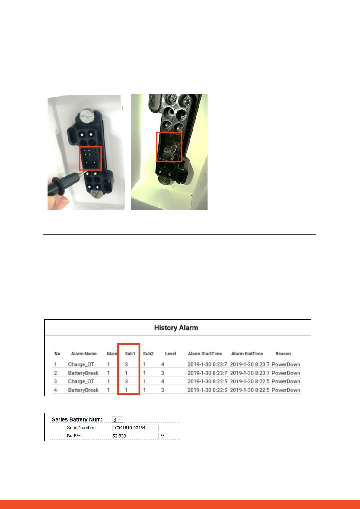
2.12 Identifying a faulty module (Variant 1)
In the web-interface of the battery, event messages and also error codes are displayed. "Current Alarm" shows
current and active messages. Past messages are logged in the “History Alarm”. If an error is displayed in the
Current Alarm or History Alarm then Sub1 shows which module is affected. Please note: The module number has
nothing to do with the stacking order! The module numbering is based on the production date and the oldest
module has the number 1. The corresponding serial number can be obtained in "RUN Data" if you select the
module number there. In the example below, the message "Charge_OT" is reported by module 3.
In Run Data, the correct serial number can be found for module 3:
8
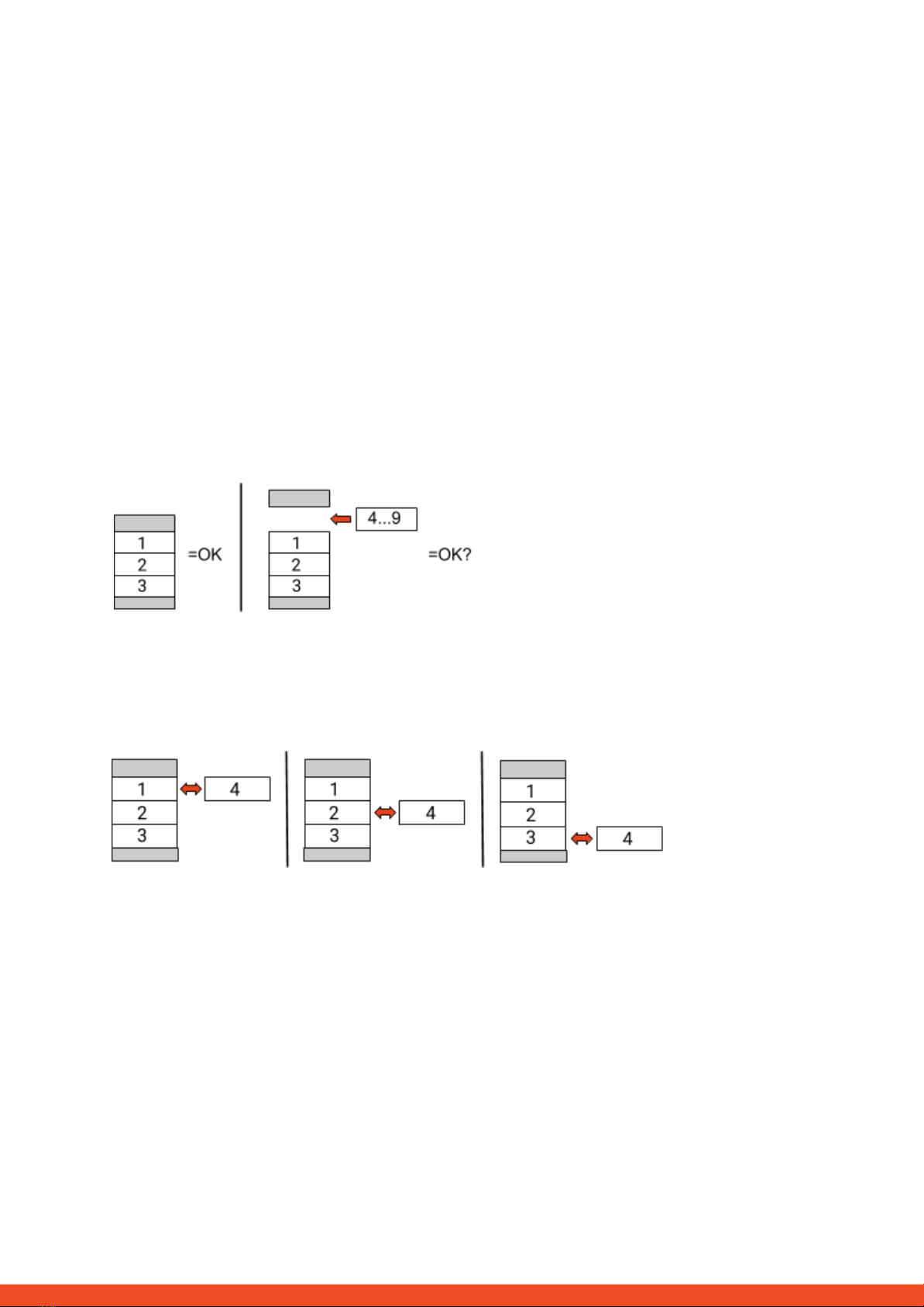
2.13 Identifying a faulty module (Variant 2)
Important:
- The number of modules must always be adapted in the Web Interface (Installation Config) as soon as
modules are added or removed from the system.
- Please perform a visual check of the communication pins according to step 2.11 for each module.
1. Build the Battery-Box with only 3 Modules (+ Base and BCU). Adjust module amount in the Web Interface under
Installation Config. Note: The module amount must be adjusted whenever the number of modules is changed.
2. Check status:
Note:
The battery status is OK when battery is on (Air Switch up and WIFI available) & no errors are shown (Web
Interface: Current Alarm). Otherwise, the battery status is NOT OK.
OK:
Add one module at a time, adjust module number in web interface and check again. If battery status turns to
“NOT OK”, then the defect module is identified to be the one that has been added newly.
NOT OK:
The defect module is probably one of the 3 modules in the tower. Take one of the spare modules and exchange
each of the 3 modules with the spare module one at a time. Check the battery status after each step. If battery
status turns to “OK”, the defect module is the one that was exchanged.
3. If the defective module is found, it may be replaced by a new replacement module. Please contact
EFT-Systems.
9
3. SERVICE TASKS
Please go through the general steps beforehand, see chapter 1.
3.1 BCU replacement
Have you detected a faulty BCU?:
After replacing the BCU, please do not forget to re-do the configuration in the web interface (enter the number of
modules and inverter brand) and install the latest BCU software approved for the inverter.
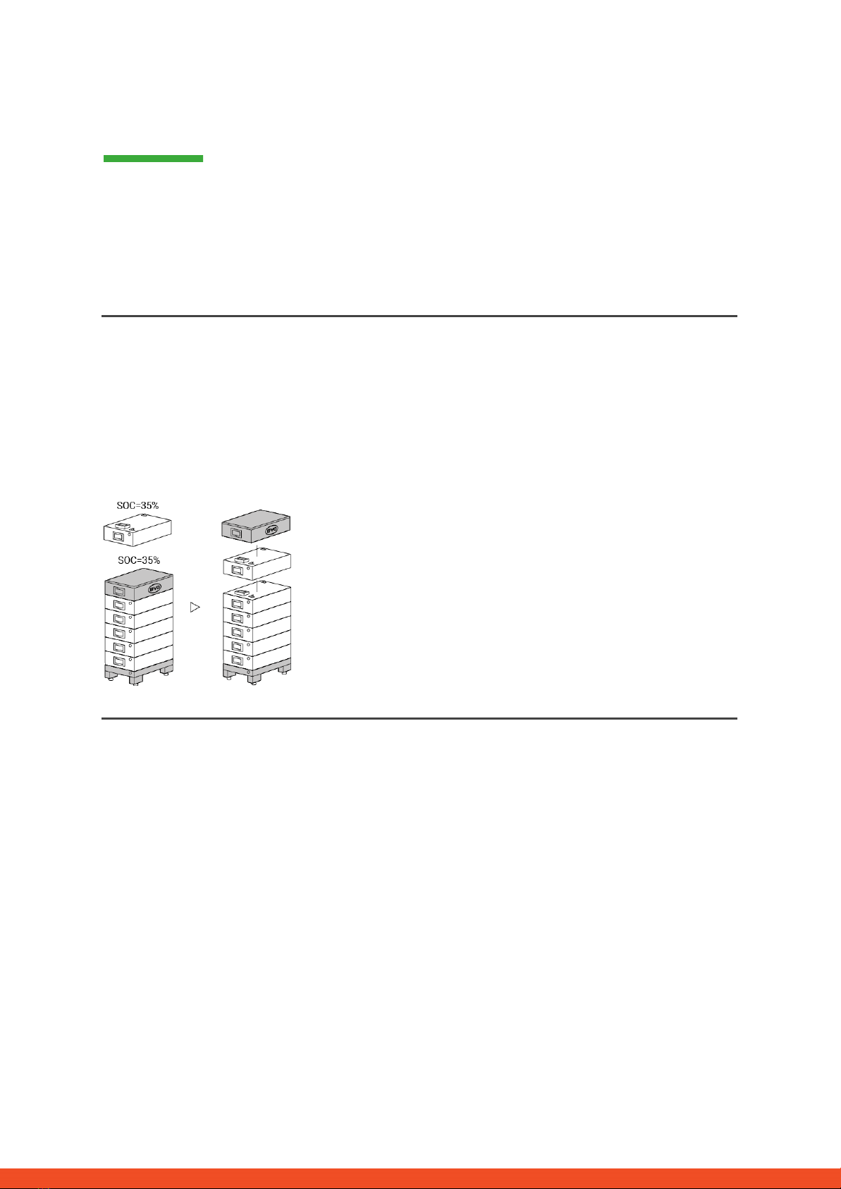
3.2 Module Replacement
Have you detected a faulty module?:
In the meantime you can use the battery system with the remaining modules and a correspondingly reduced
capacity (take into account the minimum number of modules).
Please note: It is important that all modules of a battery tower have a similar state of charge (SOC) with a
tolerance of 5%. New modules have about 35% SOC. If the remaining modules have not yet been put into
operation (not charged / discharged), the new module can easily be added. Otherwise, it is basically a module
extension. In this case, please add the new module to the system only when the system has a SOC between 30%
and 40% (see extension manual).
3.3 Charging with external HV charger
You will receive a charger from us (eg because of the message "Cell_UV")?
Each module should be individually connected to the charger and charged to the same state of charge (SOC).
The charger has a display in which you can set the desired SOC. It's enough if you select 10% SOC. It is very
important that all modules receive exactly the same amount of energy and come to the same SOC level. Please
pay attention to the display or charging time. Before charging, the module must have been at rest for at least 30
minutes. If the charging process is interrupted, then you have to wait at least 30 minutes before the module can
be recharged. (Otherwise the SOC will not be correct)
10

4. SERVICE CONTACT
Please note that this document is intended as a quick reference guide to quickly resolve common problems.
Further information and detailed installation assistance can be found at www.eft-systems.de.
To ensure a smooth process, please register yourself and the system under www.eft-systems.de.
For further help please contact:
EFT-Systems GmbH
Mail: [email protected]
Phone: +49 9352 8523999
IMPORTANT:
In order to be able to process a service case, it is absolutely necessary to get the serial number of the BCU and
all error-specific information, see the table below:
No.
Name
Description
A
Serial number BCU
At the system switch or on the Web interface (Device Information)
B
Photo of the BCU
Complete BCU (inside)
C
Photos of
Communication port
(PIN) in the BCU and
inverter.
In the BCU (detail photo) and on the inverter
D
D1
D2
D3
D4
D5
Screenshots of the web
interface:
- Device Information
- Installation Config
- Current Alarm
- History Alarm
- Run Data
On the web interface
E
Serial number of the
faulty module
(Note: only necessary, if a
faulty module was found!)
On top of the module or on the side of it.
F
Inverter serial number and
model
Important for EFT Systems to analyze and resolve the problem at system level
with the inverter partner.
G
If necessary: Delivery
address
If replacement parts are required we need:
- Complete delivery address (including country)
- Contact person
- Telephone number
H
Additional information
If available, please support us with additional information (eg comments /
information displayed on inverter / additional photos of the system / voltages / ...).
11
This manual suits for next models
6
Table of contents


