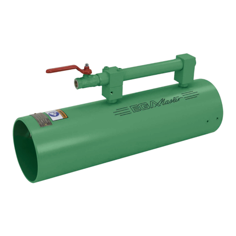
EGAmaster 79620 User manual

COD.79620
MANUAL DE INSTRUCCIONES
OPERATING INSTRUCTIONS
ESPAÑOL ............................... 2
ENGLISH................................ 8
GARANTIA / GUARANTEE... 15
VENTILADOR AXIAL / AXIAL FAN

2
ESPECIFICACIONES TÉCNICAS
Asegúrese de que
está familiarizado con el
manual de instrucciones
antes de operar con esta
máquina.
Máxima presión de trabajo 5 bar
Longitud de la unidad 350 mm
Diámetro nominal 300 mm
Caudal de ventilación 0.57 m³/ s
Peso 13 kg
Consumo de aire (soplado) 0.45 m³/min
Designación ATEX Grupo II; Categoría 2 G c IIB T 6
Nivel sonoro a 1 m de distancia 85.7 dB(A)
ESPAÑOL

3
INSTRUCCIONES DE SEGURIDAD
Cualquier herramienta eléctrica puede ser peligrosa.
Por favor, siga estos simples procedimientos.
Son para su protección.
Siga los Procedimientos de seguridad y prevención actuales de accidentes.
Nunca trabaje bajo la inuencia del alcohol, drogas o medicamentos fuertes.
Mantenga su área de trabajo limpia y despejada.
Mantenga a los niños alejados.
Apague la máquina si se detiene, por cualquier motivo, para evitar un arranque inesperado en
condiciones no controladas.
No utilice la herramienta si está dañada, mal ajustada o si no está completa y correctamente
montada.
Revise la manguera de aire para ver si hay daños.
Los ventiladores instalados al aire libre o verticalmente deben estar equipados con un techo de
protección contra la lluvia. Tenga en cuenta que el usuario es el único responsable de la instalación
del ventilador.
Verique si hay piezas dañadas.
Antes de usar la máquina, debe revisarse cuidadosamente posibles daños en las piezas o en los
dispositivos de protección para asegurarse de que funcionen correctamente y cumplan con la función
designada. Verique la alineación, las conexiones y la jación de las piezas móviles. Las piezas o
dispositivos de protección que estén dañados deberían ser intercambiados o reparados únicamente
por personal calicado. Lo mismo se aplica a interruptores defectuosos y activadores de válvulas. Si la
máquina no puede encenderse o apagarse con el gatillo de la válvula, no debe usarse.
Solo opere la herramienta después de una formación completa o bajo la supervisión de un
instructor.
Nunca exceda la presión máxima de operación.
Seguir las disposiciones nacionales vigentes en el país de aplicación.
¡ATENCIÓN! ¡Nunca use la manguera exible como un asa para su elevación!
USO CORRECTO
Solo el personal calicado puede operar la máquina.
Utilice el ventilador solo después de haberlo montado de forma segura y estando equipado con
protección contra el contacto. Retire las rejillas protectoras de fábrica provistas solo para limpiarlas
y recuerde volverlas a colocar antes de usarlas. Antes de trabajar con en el ventilador, desconecte
siempre la manguera de aire. Conecte a tierra el ventilador para evitar la electricidad estática.
USO INAPROPIADO
Cualquier uso que se desvíe del uso correcto tal y como se describe en el apartado anterior, se
considera un uso incorrecto.
Trabajar sin equipo de protección personal.

4
ZONAS PELIGROSAS
Condiciones
operacionales
----------------
Fase de vida
Funcionamiento
normal
Mal
funcionamiento
Uso
inapropiado
Uso
esperado
Transporte
Transporte de
la máquina en
estado inoperable
Dejar caer la
maquina
Transporte de
la máquina en
estado operable
Desconocido
Manejo
La máquina solo
funciona con
válvula accionada
La máquina
funciona sin
válvula accionada
La válvula está
bloqueada en
condición activa
Desconocido
INSTRUCCIONES DE OPERACIÓN
El motor cumple con las disposiciones de la Directiva 94/9 / CE (Atex 95a).
El impulsor y la carcasa están fabricados con materiales con bajo riesgo de generar calor o
chispas, por si hubiera un problema en el manejo.
Almacene el ventilador en su embalaje original en un lugar seco y protéjalo contra la humedad. Si
se almacena durante un período prolongado, verique que los rodamientos del impulsor se muevan
libremente girándolo con la mano.
Por favor, asegúrese de que no haya materiales extraño, ej. partículas de pintura que entren en el
ujo de aire y causen daños al impulsor.
Use rejillas de protección para evitar que partículas extrañas entren en los oricios de succión y
escape.
No deforme los ventiladores mediante una sujeción inadecuada.
Tenga cuidado de no dañar la carcasa ni ninguna pieza móvil.
Cuando trabaje con el ventilador (como en el ensamblaje, el uso, el mantenimiento y la reparación)
asegúrese de que el espacio sea el mismo en todas las direcciones con una distancia mínima entre
estas partes de al menos el 1% del diámetro de contacto más grande.
Antes de usarlo, desconecte la manguera de aire.
La turbina de potencia no debe ser lubricada. No utilice ningún aceite en la manguera (no use
engrasadores de línea).
La reparación del ventilador sólo debe ser realizada por trabajadores cualicados y formados. Las
instrucciones y directivas tienen que ser guardadas.
La grasa envasada en los cojinetes es suciente para al menos aprox. 5000 horas de trabajo.
Después de este tiempo, desmonte, limpie y rellene de 1/3 a 1/2 con grasa antifricción de alta calidad.
Reemplace los rodamientos dañados. Asegúrese de que los ventiladores estén montados por personal
competente y capacitado.

5
REPUESTOS Y ACCESORIOS
Solo se pueden usar piezas de repuesto originales. No se ofrece ninguna garantía por daños y se
rechaza la responsabilidad, si se utilizan repuestos y accesorios no originales.
La reparación de la máquina solo está permitida por empresas expertas autorizadas.
Problema Causa Remedio
a La máquina no se enciende Aire no conectado Conectar y abrir la línea de
aire
b La máquina gira demasiado
despacio
Presión de funcionamiento
demasiado baja
Aumente la presión de
operación (en la máquina) a
5 bar
c Caja de cambios hace
ruidos fuertes -Póngase en contacto con
una empresa experta
d Otros problemas - Póngase en contacto con
una empresa experta
INSTRUCCIONES DE REPARACIÓN
Desmontaje y montaje.
El desmontaje y el montaje solo deben realizarse utilizando el despiece.
Desarme la herramienta solo, si tiene el conocimiento técnico y la formación apropiada.
Mantenga los contaminantes como la suciedad y la arena lejos de las partes internas en todo
momento.
Siempre determine y corrija la causa del problema antes de volver a armarlo. Si la causa original no
se corrige, puede provocar un desgaste adicional y un fallo en la herramienta.
Piezas de repuesto
Solo se pueden usar piezas de repuesto originales. No se ofrece ninguna garantía por daños y se
rechaza la responsabilidad, si se utilizan repuestos y accesorios no originales.

6
LISTA DE PIEZAS DE REPUESTO
Ventilador axial neumático
Item Qty. Descripción Notas
1 1 Caja de ventilador
2 1 Acoplamiento de rosca externo R 1/2 ''
3 1 Chapa de conducto de aire, conj.
4 4 Tornillo hexagonal
5 2 Tornillo hexagonal
6 6 Tuerca hexagonal
7 6 Arandela de seguridad dentada
8 1 Chapa de conducto de aire, conj.
9 1 ND 300 mm
10 3 Tornillo hexagonal
11 3 Arandela de seguridad dentada
12 1 Arandela
13 1 Alojamiento del cojinete
14 1 Casquillo espaciador
15 1 Eje, conj.
16 2 cojinete de bolas de contacto angular *
17 2 Tuerca hexagonal
18 2 Arandela de seguridad dentada
19 4 Tornillo hexagonal
20 4 Arandela de seguridad dentada
21 1 Impulsor, conj.
22 1 Rueda de turbina, conj.
23 1 Asa, conj.
24 1 Campana silenciadora, conj.
25 3 Tornillo de taladro
30 1 Tornillo hexagonal
31 2 Tuerca hexagonal
32 3 Arandela dentada
* Piezas de desgaste que deberían almacenarse en caso de uso continuo.

7

8
TECHNICAL SPECIFICATION
Before operating
this machine make
sure, that you are familiar
with the operating
instructions.
Max. Operation pressure 5 bar
Unit length 350 mm
Nominal diameter 300 mm
Volume ow (unrestricted discharge) 0.57 m³/ sec
Weight 13 kg
Air consumption (blowing) 0.45 m³/min
ATEX classication Group II; Category 2 G c IIB T 6
Noise level at 1 m distance 85.7 dB(A)
ENGLISH

9
SAFETY INSTRUCTIONS
Any power tool can be dangerous.
Please follow these simple procedures.
They are for your protection.
Follow the general current and appropriate Accident Prevention and Safety Procedures.
Never work under the inuence of alcohol, drugs or stronger medication.
Keep your working area clean and uncluttered.
Keep children away.
Switch o the machine if it stops - for any reason - to avoid the unexpected starting in uncontrolled
condition.
Do not operate the tool if it is damaged, improperly adjusted or not completely and correctly
assembled.
Check air hose for damage.
Fans installed in the open or vertically should be equipped with a rain protection roof. Please be
informed that the user only is responsible for the installation of the fan.
Check damaged parts.
Before using the machine, damaged parts or protective devices should be carefully checked to
make sure they work soundly and full the designated function. Check alignment, connections and
attachment of moving parts. Also check if parts are broken. Parts or protective devices that are
damaged should, if nothing else is mentioned in these operating instructions, only be exchanged
or repaired by qualied personnel. The same applies to defective switches and valve triggers. If the
machine cannot be switched on or o with the valve trigger, it should not be used.
Only operate the tool after a thorough training or under supervision of a trainer.
Never exceed the maximum operation pressure.
Follow the valid national provisions in the country of application.
ATTENTION! Never use the exible hose as a lifting handle!
INTENDED USE
Skilled personnel only is allowed to operate the machine.
Only use the fan after it has been securely mounted and tted with protection against contact to suit
the application. Remove factory-provided protective grilles only for cleaning and remember to re-t
them before use. Before working on the fan always disconnect the air hose. Earth the fan against static
electricity.
IMPROPER USE
Any use deviating from the intended use as described is considered to be improper use.
Working without personal protection equipment.

10
DANGER ZONES
Operational
condition
----------------
Life phase
Normal function Malfunction Improper use Expected use
Transport
Transport of
the machine in
an inoperable
condition
Drop of the
machine
Transport of the
machine in an
operable condition
unknown
Operation
Machine only
works with
actuated valve
Machine runs
without actuated
valve
Valve is blocked in
actuated condition unknown
OPERATION INSTRUCTION
The motor complies with the provisions of the Directive 94/9/EC (Atex 95a).
The impeller and casing are made of materials with a reduced risk of generating heat or sparks, if
there should be an operational problem.
Store fan in its original packing at a dry place and protect it against the weather. If stored for a long
period, check the impeller bearings move freely by turning it by hand.
Please ensure no foreign matter e.g. paint particles get into the airow and causes damage to the
impeller.
Use protective grilles to prevent foreign particles from getting into the suction and exhaust holes.
Do not deform the fans by improper fastening.
Be careful not to damage the casing or any moving parts.
The gap between impeller and casing is properly set when the fan was manufactured.
When working at the fan (like assembly, operation, maintenance and repair) ensure gap is the same
all the way around with a minimum distance between these parts of at least 1% of the greatest contact
diameter.
Prior to operation, blow out the air hose and connect it to the plug cock.
The power turbine must not be lubricated. Do not ll any oil in the hose (do not use line oilers).
Repair of the fan should only be performed by qualied and skilled workers. Instructions and
directives have to be kept.
Bearing clearance too large?
Lubricant on the bearing?
Unusual noise?
The grease packed in the bearings is sucient to at least approx. 5000 working hours. After
this time dismantle, clean and ll 1/3 to 1/2 with high quality antifriction grease. Replace damaged
bearings. Ensure fans are mounted by competent, trained personnel.

11
SPARE PARTS AND ACCESSORIES
Only original spare parts may be used. There is no warranty for damages and liability is
disclaimed, if non-original spare parts and accessories are used.
The repairing of the machine is allowed authorized expert companies only.
The accessories applicable with our machine are listed in our brochure.
Problem Cause Remedy
a Machine does not start Air not connected Connect and open air line
b Machine rotates too slowly Operating pressure too low Increase operating pressure
(on the machine) to 6 bar
c Gearbox makes strong noise -Contact authorized expert
company
d Other problems -Contact authorized expert
company
REPAIR INSTRUCTION
Disassembly and re-assembly.
Dismantling and assembly should only be carried out using the sectional drawing.
Disassemble the tool until only, if you are skilled and have the appropriate technical knowledge.
Then only disassemble the tool as necessary to repair as required.
Keep contaminants such as dirt and grit away from the internal parts at all times.
Always determine and correct the cause of the problem prior to re-assembly. Further wear and tool
failure can result, if the original cause is not corrected.
Spare Parts
Only original spare parts may be used. There is no warranty for damages and liability is
disclaimed, if non-original spare parts and accessories are used.

12
SPARE PART LIST
Pneumatic Axial Fan
Item Qty. Description Remarks
1 1 Fan housing
2 1 External thread coupling R 1/2''
3 1 Air duct sheet metal, assy.
4 4 Hexagonal screw
5 2 Hexagonal screw
6 6 Hexagonal nut
7 6 Toothed lock washer
8 1 Air duct sheet metal, assy.
9 1 Protective grille ND 300 mm
10 3 Hexagonal screw
11 3 Toothed lock washer
12 1 Washer
13 1 Bearing housing
14 1 Spacer bushing
15 1 Shaft, assy.
16 2 Angular contact ball bearing *
17 2 Hexagonal nut
18 2 Toothed lock washer
19 4 Hexagonal screw
20 4 Toothed lock washer
21 1 Impeller, assy.
22 1 Turbine wheel, assy.
23 1 Handle, Assy.
24 1 Silencer hood, assy.
25 3 Drill screw
30 1 Hexagonal screw
31 2 Hexagonal nut
32 3 Serrated washer
* Wear and tear parts to be stored in case of continuous use.

13

14


Table of contents
Languages:
Other EGAmaster Fan manuals
Popular Fan manuals by other brands

Johnson
Johnson Maestrale43 Instructions for use
Fantech
Fantech PB Series Installation, operation & maintenance manual
SPT
SPT SF-1041 owner's manual

UNITED
UNITED USF-617 instruction manual

Mondial Designs Limited
Mondial Designs Limited V-68-6P Instruction and Technical Service Manual
Aardee
Aardee AARF-30 user guide

ecoQ
ecoQ SilentAir Grande instruction manual
NOVENCO
NOVENCO RS35x-CX0-E series Installation and maintenance instructions
Greenheck
Greenheck FGI Fabra Hood Assembly instructions
Minka-Aire
Minka-Aire Wind instruction manual

Stelpro
Stelpro ULTRA SILENCIEUX Series installation guide

Caframo
Caframo Stor-Dry 9406 operating instructions
