EGAmaster 79623 User manual
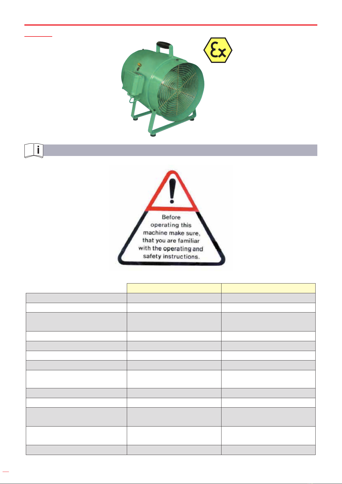
VENTILADOR AXIAL / AXIAL FAN
COD.79623
COD.79624
MANUAL DE INSTRUCCIONES
OPERATING INSTRUCTIONS
ESPAÑOL ............................... 2
ENGLISH.............................. 10
GARANTIA / GUARANTEE... 19
2
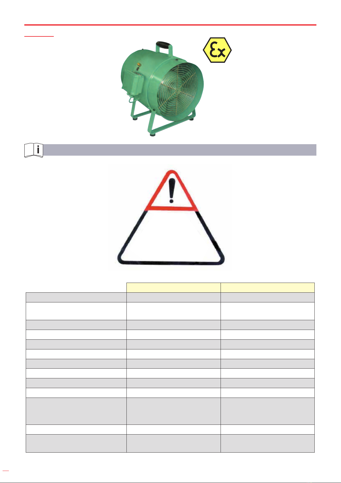
ESPECIFICACIONES TÉCNICAS
Asegúrese de que
está familiarizado
con el manual de
instrucciones antes
de operar con esta
máquina.
COD. 79623 COD. 79624
Longitud de la unidad 390 mm 390 mm
Caudal de ventilación- sin
restricciones 1,5 m bar 1.0 m³/ sec 1.0 m³/ sec
-a contrapresión- 1,5 milibar 1.0 m³/ sec 1.0 m³/ sec
-a contrapresión- 2,5 milibar 0.8 m³/sec 0.8 m³/sec
-a contrapresión- 3,5 milibar 0.6 m³/sec 0.6 m³/sec
Conexión del conducto ujo 300 mm dia. fkujo 300 mm dia.
Peso 20.5 kg 20.5 kg
Voltaje 110V, 50Hz monofásico, AC 230V, 1Ph, 50Hz, AC
Rendimiento del motor 0.37 kW 0.37 kW
Sistema de protección IP 55 IP 55
Clases de protección de
ignición
Motor eléctrico
EX-e-II- T3 EX-e-II-T4
Clasicación ATEX II 2G c IIB T3 II 2G c IIB T3
Nivel sonoro a 1 metro de
distancia 84.9 dB(A) 84.8 dB(A)
ESPAÑOL

3
INSTRUCCIONES DE SEGURIDAD
Cualquier herramienta puede ser peligrosa. Por favor siga estos simples procedimientos.
Hágalo por su seguridad.
Siga los procedimientos apropiados y actualizados de seguridad y prevención.
Nunca trabaje bajo la inuencia del alcohol, drogas o fuerte medicación.
Mantenga su área de trabajo limpia y recogida.
Mantenga a los niños alejados.
Apague la máquina si se detiene-por cualquier razón-para evitar la puesta en marcha imprevista
en condiciones incontroladas.
Desconecte de la toma de corriente y compruebe si el interruptor está apagado, durante el
montaje y desmontaje y cuando adapta/ajusta los respectivos accesorios.
No opere la máquina si está dañada, ajustada de manera inapropiada o no está montada por
completo.
Antes de cualquier uso compruebe la máquina, el cableado y el enchufe. Los desperfectos
tienen que ser reparados únicamente por un especialista autorizado. Compruebe que la máquina
está apagada antes de enchufarse a la toma de corriente.
Los ventiladores que estuvieran instalados al aire libre o verticalmente deberían equiparse con
una protección contra la lluvia. Por favor, considere que el usurario solo es responsable de la
instalación del ventilador.
No toque los cables durante el uso de la maquinaria si la línea de alimentación está dañada.
Desconéctela inmediatamente de la fuente de energía. Nunca use una máquina con una línea de
alimentación defectuosa.
Tenga siempre en cuenta el momento de reacción de la máquina.
No toque las partes giratorias.
Antes de transportarla apague el motor y desenchúfelo de la toma de corriente.
Revise las partes dañadas. Antes de usar la máquina, las partes dañadas o los dispositivos de
protección deberían revisarse cuidadosamente para asegurarse de que trabajan cumpliendo con la
función para la que han sido diseñados. Revise la alimentación, las conexiones y el acoplamiento
de las partes móviles. Revise también si hay partes rotas. Las piezas o los dispositivos de protección
que están dañados solo deberían ser reparados o cambiados por personal cualicado, si no se
especica lo contrario. Se aplica lo mismo a los interruptores defectuosos y a los gatillos. La
máquina no debería emplearse si la máquina no se puede encender ni apagar con el gatillo.
Emplee la máquina solo después de estar capacitado para ello o bajo la supervisión de personal
cualicado.
No exceda nunca la presión máxima de operación.
Para adquirir el producto acuda a un proveedor nacional valido.
4
APLICACIÓN
Solo el personal cualicado, podrá operar con la máquina.
Conecte a tierra el ventilador para evitar electricidad estática.
Instale la guarda protectora antes del encendido. Asegúrese de que las entradas desprotegidas y
las salidas de descarga están equipadas con protección contra el contacto.
Retire las rejillas protectoras de fábrica únicamente para limpiarlas.
USO INAPROPIADO
Cualquier desviación del uso apropiado descrito, se considerará un uso inapropiado.
Trabajar sin el equipamiento de protección personal.
ZONAS PELIGROSAS
Condición
operativa
----------------
Etapa de vida
Función normal Fallo Uso inaporppiado Uso apropiado
Transporte
Transporte de
la máquina en
reposo
Caída de la
máquina
Transporte de la
máquina en uso Desconocido
Operación
La máquina
solo trabaja con
una válvula de
actuación
La máquina
trabaja sin válvula
de actuación
La válvula está
bloqueada en
operación
Desconocido
INSTRUCCIONES DE OPERACIÓN
Motor monofásico AC con sistema de tracción (sistema de protección IP 55) 79623-110V,
79624-230V, clase de aislamiento F. Temperatura ambiente de 20°C a +40°C. El caudal nominal
asciende al 100 % del rendimiento del motor por encima de los 1000 m sobre el nivel del mar.
Conecte el contacto de acuerdo con las instrucciones del motor del fabricante. Los dispositivos
de seguridad deben instalarse antes de la puesta en marcha de la máquina. Asegúrese de que las
entradas sin protección y las salidas están equipadas con protección contra el contacto.
¡Atención a la conexión!
Estos trabajos deben realizarse con la máquina apagada. La tensión y la frecuencia de línea
deben de concordar con los datos de la placa de datos de servicio. Se permite una desviación de
un 5% en el voltaje o la frecuencia sin que se produzca una reducción en el rendimiento. Conecte
y coloque el arco del interruptor de acuerdo con lo explicitado en el diagrama de conexiones
contenido en el cuadro de sujeción. Conecte el conductor de protección con esta abrazadera
Lubricación
Vea las instrucciones en el manual del fabricante del motor.

5
Mantenimiento e instrucciones de montaje
La lubricación de los cojinetes de fricción del motor debe hacerse de acuerdo con las
instrucciones del fabricante del motor. El funcionamiento del ventilador tiene que comprobarse
regularmente. Un funcionamiento inestable puede darse por desgaste (desequilibrado) o daños en
el impulsor ocasionados por la presencia de agentes extraños. Siga los pasos adecuados (limpieza,
cambio de las piezas defectuosas o puesta a punto) cuando las causas de esos mismos daños o del
mal funcionamiento se hayan identicado correctamente. Una mala puesta en marcha da lugar a
vibraciones y a fallos en el material.
INSTRUCCIONES DE REPARACIÓN
Montaje y desmontaje. El montaje y desmontaje deberían llevarse a cabo siguiendo
rigurosamente los planos de sección. Desmonte la herramienta únicamente si ha sido formado
para esta actividad y tiene el conocimiento técnico preciso. Y solo desmonte la unidad si fuera
necesaria alguna reparación. Mantenga en todo momento los agentes contaminantes tales como la
suciedad o la arenilla lejos de las partes internas. Corrija y je siempre la causa del problema antes
de volver a montar la unidad. Si la causa original del problema no se ha resuelto con éxito puede
dar lugar a un desgaste mayor y a un fallo de la herramienta.
PIEZAS Y ACCESORIOS DE REPUESTO
Solo se pueden utilizar partes de repuesto originales. No hay garantía, ni nos hacemos
responsables de los daños en caso de que se empleen partes o accesorios que no sean originales.
La reparación de las máquinas, solo está autorizada si las llevan a cabo compañías con expertos
autorizadas para ello.
Los accesorios aplicables a nuestras máquinas se muestran en nuestro folleto.
Problema Causa Solución
a El motor no arranca No se ha conectado a la
fuente de alimentación
Conecte a la fuente de
alimentación
b Otros problemas -
Póngase en contacto con
la compáia experta
autorizada

6
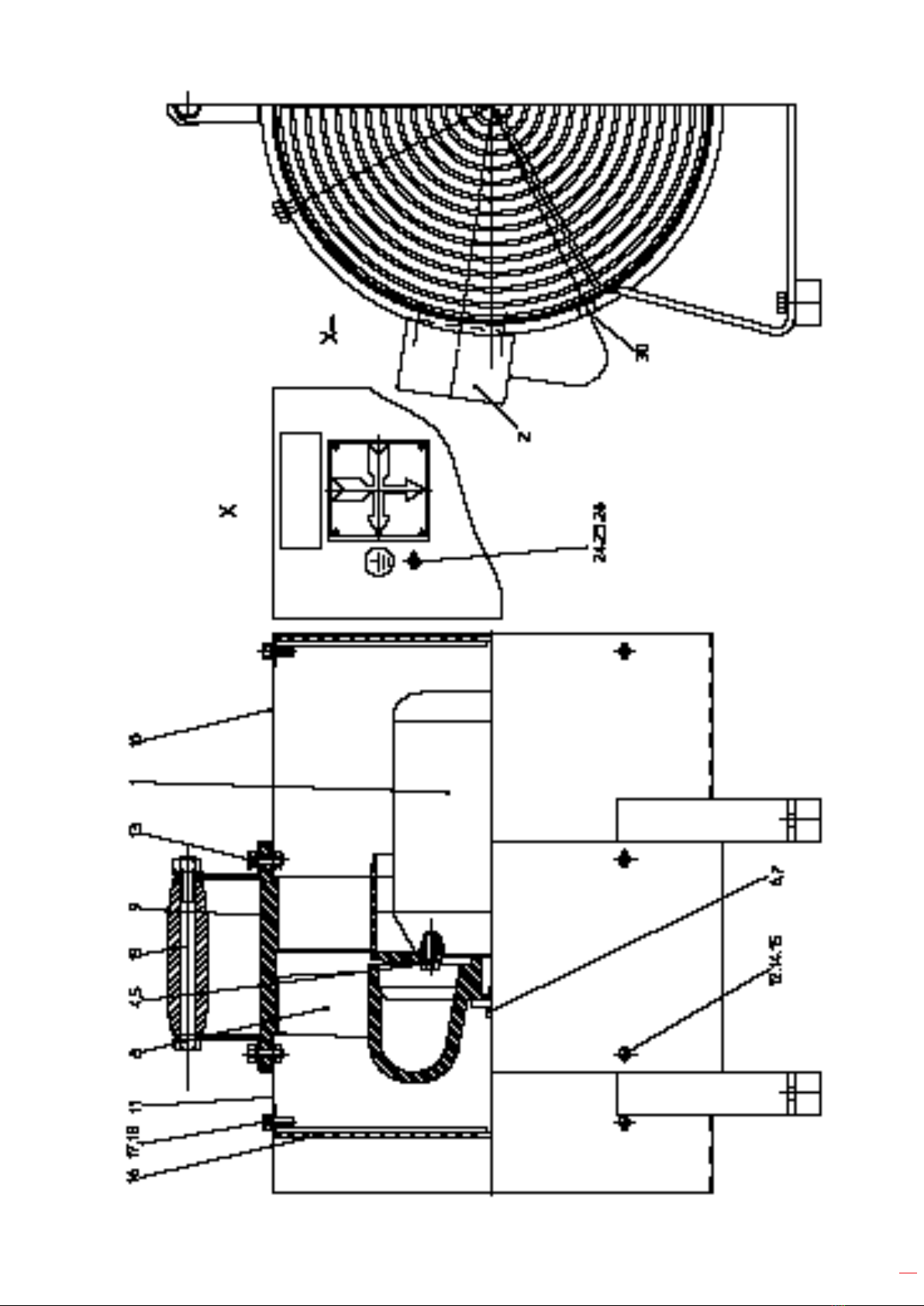
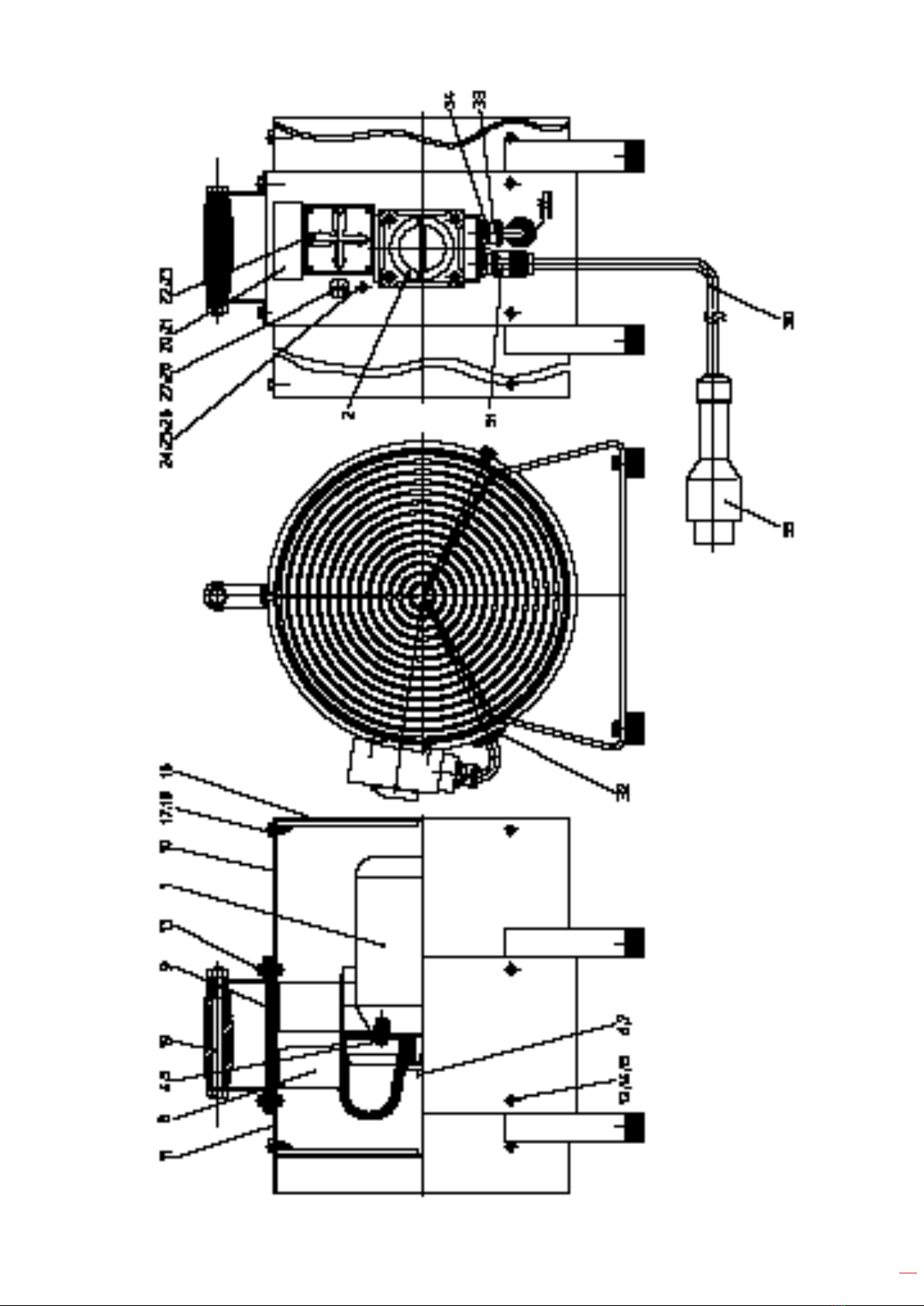
PIEZAS DE REPUESTO
Solo se utilizarán piezas de repuesto originales. La garantía del producto se invalidará y la
empresa no se hará cargo de los daños si se utilizan piezas de repuesto y accesorios no originales.
Ventilador axial eléctrico - COD. 79623
Item Qty. Descripción
1 Motor monofásico Eex 110 V, 50 Hz
1 1 Motor monofásico Eex 110 V, 50 Hz
2 1 Interruptor de instalación
4 4 Tornillo hexagonal
5 4 Arandela de retención dentada
6 1 Tornillo cabeza cilíndrica
7 1 Arandela
8 1 Impulsor
9 1 Carcasa con control
10 1 Protección, montaje.
11 1 Protección, montaje
12 4 Tornillo hexagonal
13 2 Tornillo hexagonal
14 6 Tuerca hexagonal
15 6 Arandela de retención dentada
16 2 Rejilla protectora
17 6 Tornillo hexagonal
18 6 Arandela de retención dentada
19 1 Asa
24 1 Tornillo hexagonal
25 2 Tuerca hexagonal
26 3 Disco de ventilador
30 1 Cable de conexión de alimentación
31 1 Prensaestopa
32 1 Boquilla de paso
33 1 Prensaestopa
34 2 Reducción
35 1 Enchufe

7
8
Ventilador axial eléctrico - COD. 79624
Item Qty. Descripción
1Motor monofásico Eex 230V, 50 Hz con caja de conexiones
1 1 Motor monofásico Eex 230V, 50 Hz
2 2 Caja de conexiones
4 4 Tornillo hexagonal
5 4 Arandela de retención dentada
6 1 Tornillo cabeza cilíndrica
7 1 Arandela
8 1 Impulsor
9 1 Carcasa
10 1 Protección, montaje
11 1 Protección, montaje
12 4 Tornillo hexagonal
13 2 Tornillo hexagonal
14 6 Tuerca hexagonal
15 6 Arandela de retención dentada
16 2 Rejilla protectora
17 6 Tornillo hexagonal
18 6 Arandela de retención dentada
19 1 Asa
24 1 Tornillo hexagonal
25 2 Tuerca hexagonal
26 3 Disco de ventilador
30 1 Boquilla
9
10
TECHNICAL SPECIFICATION
COD. 79623 COD. 79624
Unit length 390 mm 390 mm
Volume ow - unrestricted 1.0 m³/ sec 1.0 m³/ sec
- at counter pressure -
1, 5 m bar 1.0 m³/ sec 1.0 m³/ sec
- at counter pressure - 2,5 m bar 0.8 m³/sec 0.8 m³/sec
- at counter pressure - 3,5 m bar 0.6 m³/sec 0.6 m³/sec
Connection of duct ush for 300 ush for 300 mm dia.
Weight 20.5 kg 20.5 kg
Voltage 110 V, 50 Hz single-phase,
AC 230 V, 1 Ph., 50 Hz, AC
Motor output 0.37 kW 0.37 kW
Protective system IP 55 IP 55
Type of explosion protection
Electric motor EX-e-II- T3 EX-e-II-T4
ATEX specication
Fan II 2G c IIB T3 II 2G c IIB T3
Noise level at 1 m distance 84.9 dB(A) 84.8 dB(A)
ENGLISH

11
SAFETY INSTRUCTIONS
Any tool can be dangerous.
Please follow these simple procedures.
They are for your protection.
Follow the general current and appropriate Accident Prevention and Safety Procedures.
Never work under the inuence of alcohol, drugs or stronger medication.
Keep your working area clean and uncluttered.
Keep children away.
Switch off the machine if it stops - for any reason - to avoid the unexpected starting in
uncontrolled condition.
Unplug power supply and check, if the switch is off, when the machine is in an uncontrolled
condition, during assembly and disassembly and when adjusting resp. tting an accessory part.
Do not operate the tool if it is damaged, improperly adjusted or not completely and correctly
assembled.
Before every use check the machine, cable and plug. Damages have to be eliminated by an
authorised specialist only. Take care that the machine is switched off when the plug is inserted into
a power receptacle.
Fans installed in the open or vertically should be equipped with a rain protection roof. Please be
informed that the user only is responsible for the installation of the fan.
Do not touch the cable, if the power supply line is damaged during work.
Immediately disconnect power supply. Never apply a machine with defective power supply line.
Always consider the reaction moment of the machine.
Do not touch rotating parts.
Always switch off the motor disconnect power before transport.
Check damaged parts. Before using the machine, damaged parts or protective devices should
be carefully checked to make sure they work soundly and full the designated function. Check
alignment, connections and attachment of moving parts. Also check if parts are broken. Parts
or protective devices that are damaged should, if nothing else is mentioned in these operating
instructions, only be exchanged or repaired by qualied personnel. The same applies to defective
switches and valve triggers. If the machine cannot be switched on or off with the valve trigger, it
should not be used.
Only operate the tool after a thorough training or under supervision of a trainer.
Follow the valid national provisions in the country of application.
12
INTENDED USE
Skilled personnel only is allowed to operate the machine.
Earth the fan against static electricity!
Safety guard should be tted before starting. Ensure that unprotected intake and blow-off outlet is
tted with protection against contact.
Remove factory-provided protective grilles for cleaning only.
IMPROPER USE
Any use deviating from the intended use as described is considered to be improper use.
Working without personal protection equipment.
DANGER ZONES
Operational
condition
----------------
Life phase
Normal function Malfunction Improper use Expected use
Transport
Transport of the
machine in an
inoperable
condition
Drop of the
machine
Transport of the
machine in an
operable
condition
unknown
Operation
Machine only
works with
actuated switch
Machine runs
without actuated
switch
Switch is blocked
in actuated
condition
unknown
OPERATION INSTRUCTION
Drive System
Single-Phase-AC motor (protective system IP 55) 79623-110V, 79624-230V, insulation class F.
Environment temperature - 20°C to +40°C. The nominal output amounts to 100 % of the motor
output up to 1000 m sea level. Connect the contact according to the instructions of the motor
manufacturer. Safety guard should be tted before starting. Ensure that unprotected intake and
blow-off outlet is tted with protection against contact.
Connection Attention!
Take up all work in dead state of machine only! Main voltage and line frequency must be in
conformity with data on the rating plate. 5% voltage or frequency deviations are allowed without
reduction of output. Connect and arrange the switch bow according to the diagram of connections
contained in the clamping box. Connect protective conductor with this clamp.
Lubrication
See instructions in the manual of the motor manufacturer.
13
Maintenance and assembly instruction
The lubrication of the motor friction bearings has to be done according to the instructions of
the motor manufacturer. Quiet running of the fan must be checked regularly. Unsteady running
is caused by deposition in the impeller or by wear (unbalance) or by damage of the impeller
produced by foreign substances. Take suitable steps (cleaning, changing of defective parts, lining-
up) when the damage or cause for unsteady running is well-known. Unsteady running leads to
vibrations and faults in material.
REPAIR INSTRUCTION
Disassembly and re-assembly Dismantling and assembly should only be carried out using the
sectional drawing. Disassemble the tool until only, if you are skilled and have the appropriate
technical knowledge. Then only disassemble the tool as necessary to repair as required. Keep
contaminants such as dirt and grit away from the internal parts at all times. Always determine and
correct the cause of the problem prior to re-assembly. Further wear and tool failure can result, if the
original cause is not corrected.
SPARE PARTS AND ACCESSORIES
Only original spare parts may be used. There is no warranty for damages and liability is
disclaimed, if non-original spare parts and accessories are used. The repairing of the machine is
allowed authorized expert companies only. The accessories applicable with our machine are listed
in our brochure.
Problem Cause Remedy
a Motor doesn’ t start No connection to power
supply Connect to power supply
b Other problems Contact authorized expert
company
14
SPARE PARTS
Only original spare parts may be used. There is no warranty for damages and liability is
disclaimed, if non-original spare parts and accessories are used.
COD. 79623 - Electric Axial Fan
Item Qty. Description
1 Single-phase Motor Eex 110 V, 50 Hz
1 1 Single-phase Motor Eex 110 V, 50 Hz
2 1 Installation Switch
4 4 Hexagon screw
5 4 Toothed lock washer
6 1 Fillister-head screw
7 1 Washer
8 1 Impeller
9 1 Housing with control
10 1 Sheet cover, Assy.
11 1 Sheet cover, Assy.
12 4 Hexagonal screw
13 2 Hexagonal screw
14 6 Hexagonal nut
15 6 Toothed lock washer
16 2 Protective grille
17 6 Hexagonal screw
18 6 Toothed lock washer
19 1 Handle
24 1 Hexagonal screw
25 2 Hexagonal nut
26 3 Fan disc
30 1 Power connection cable
31 1 Cable screwing
32 1 Step nipple
33 1 Cable screwing
34 2 Reduction
35 1 Plug
15

16
COD. 79624 - Electric Axial Fan
Item Qty. Description
1 Single-phase Motor Eex 230V, 50 Hz with terminal box
1 1 Single-phase Motor Eex 230V, 50 Hz
2 2 Terminal box
4 4 Hexagonal screw
5 4 Toothed lock washer
6 1 Fillister-head screw
7 1 Washer
8 1 Impeller
9 1 Housing
10 1 Sheet cover, Assy.
11 1 Sheet cover, Assy.
12 4 Hexagonal screw
13 2 Hexagonal screw
14 6 Hexagonal nut
15 6 Toothed lock washer
16 2 Protective grille
17 6 Hexagonal screw
18 6 Toothed lock washer
19 1 Handle
24 1 Hexagonal screw
25 2 Hexagonal nut
26 3 Fan disc
30 1 Guide nozzle

17

18

ARTICULO / ITEM / ARTICLE: ....................................................................................................................
Nº DE SERIE / SERIE Nº / Nº SERIE: ...........................................................................................................
DISTRIBUIDOR / DISTRIBUTOR / DISTRIBUTEUR: ...................................................................................
PAIS / COUNTRY / PAYS: .............................................................................TEL.:....................................
FECHA DE VENTA / SALE DATE / DATE VENTE:........................................................................................
NOMBRE DEL COMPRADOR / BUYER NAME / NOM DE L’ACHETEUR:..................................................
TEL. COMPRADOR / BUYER TEL. / TEL. DE L’ACHETEUR:........................................................................
CERTIFICADO DE GARANTIA
GUARANTEE CERTIFICATE
CERTIFICAT DE GARANTIE
SELLO / STAMP / CACHET
EGA MASTER GARANTIZA AL COMPRADOR DE ESTA MAQUINA LA GARANTIA TOTAL (DURANTE 12 MESES), DE LAS PIEZAS CON DEFECTOS DE FABRICACION. ESTA GARANTIA NO CUBRE AQUELLAS
PIEZAS QUE POR SU USO NORMAL TIENEN UN DESGASTE. PARA OBTENER LA VALIDEZ DE LA GARANTIA , ES ABSOLUTAMENTE IMPRESCINDIBLE QUE COMPLETE Y REMITA ESTE DOCUMENTO A EGA
MASTER , DENTRO DE LOS SIETE DIAS A PARTIR DE LA FECHA DE COMPRA.
EGA MASTER GUARANTEES TO THE BUYER OF THIS MACHINE THE TOTAL WARRANTY (DURING 12 MONTHS), OF THE PIECES WITH MANUFACTURING FAULTS.
THIS GUARANTEE DOES NOT COVER THOSE PIECES WORN OUT DUE TO A NORMAL USE. IN ORDER TO OBTAIN THE VALIDITY OF THIS WARRANTY , IT IS ABSOLUTELY NECESSARY TO FULFILL THIS
DOCUMENT AND RESEND IT TO EGA MASTER WITHIN 7 DAYS FROM SALE DATE.
EGA MASTER GARANTIE A L’ACHETEUR DE CETTE MACHINE LA GARANTIE TOTALE (PENDANT 12 MOIS) DES PIECES AVEC DEFAUTS DE FABRICATION. CETTE GARANTIE NE COUVRE PAS LES PIECES QUE
PAR UN USAGE NORMAL, SOIENT DETERIOREES. POUR OBTENIR LA VALIDITE DE LA GARANTIE, IL EST ABSOLUMENT IMPERATIF COMPLETER ET ENVOYER CE DOCUMENT EGA MASTER, DANS UN DELAI
DE 7 JOURS A PARTIR DE LA DATE D’ACHAT.
EJEMPLAR PARA EGA MASTER / COPY FOR EGA MASTER / EXEMPLAIRE POUR EGA MASTER
ARTICULO / ITEM / ARTICLE: ....................................................................................................................
Nº DE SERIE / SERIE Nº / Nº SERIE: ...........................................................................................................
DISTRIBUIDOR / DISTRIBUTOR / DISTRIBUTEUR: ...................................................................................
PAIS / COUNTRY / PAYS: .............................................................................TEL.:....................................
FECHA DE VENTA / SALE DATE / DATE VENTE:........................................................................................
NOMBRE DEL COMPRADOR / BUYER NAME / NOM DE L’ACHETEUR:..................................................
TEL. COMPRADOR / BUYER TEL. / TEL. DE L’ACHETEUR:........................................................................
CERTIFICADO DE GARANTIA
GUARANTEE CERTIFICATE
CERTIFICAT DE GARANTIE
SELLO / STAMP / CACHET
EGA MASTER GARANTIZA AL COMPRADOR DE ESTA MAQUINA LA GARANTIA TOTAL (DURANTE 12 MESES), DE LAS PIEZAS CON DEFECTOS DE FABRICACION. ESTA GARANTIA NO CUBRE AQUELLAS
PIEZAS QUE POR SU USO NORMAL TIENEN UN DESGASTE. PARA OBTENER LA VALIDEZ DE LA GARANTIA , ES ABSOLUTAMENTE IMPRESCINDIBLE QUE COMPLETE Y REMITA ESTE DOCUMENTO A EGA
MASTER , DENTRO DE LOS SIETE DIAS A PARTIR DE LA FECHA DE COMPRA.
EGA MASTER GUARANTEES TO THE BUYER OF THIS MACHINE THE TOTAL WARRANTY (DURING 12 MONTHS), OF THE PIECES WITH MANUFACTURING FAULTS.
THIS GUARANTEE DOES NOT COVER THOSE PIECES WORN OUT DUE TO A NORMAL USE. IN ORDER TO OBTAIN THE VALIDITY OF THIS WARRANTY , IT IS ABSOLUTELY NECESSARY TO FULFILL THIS
DOCUMENT AND RESEND IT TO EGA MASTER WITHIN 7 DAYS FROM SALE DATE.
EGA MASTER GARANTIE A L’ACHETEUR DE CETTE MACHINE LA GARANTIE TOTALE (PENDANT 12 MOIS) DES PIECES AVEC DEFAUTS DE FABRICATION. CETTE GARANTIE NE COUVRE PAS LES PIECES QUE
PAR UN USAGE NORMAL, SOIENT DETERIOREES. POUR OBTENIR LA VALIDITE DE LA GARANTIE, IL EST ABSOLUMENT IMPERATIF COMPLETER ET ENVOYER CE DOCUMENT EGA MASTER, DANS UN DELAI
DE 7 JOURS A PARTIR DE LA DATE D’ACHAT.
EJEMPLAR PARA EL CLIENTE / COPY FOR THE CUSTOMER / EXEMPLAIRE POUR LE CLIENT

C/ ZORROLLETA 11, POL. IND. JUNDIZ
01015 VITORIA, SPAIN P.O.B. APTDO. 5005
TEL. 34 - 945 290 001 FAX. 34 - 945 290 141
www.egamaster.com
This manual suits for next models
1
Table of contents
Languages:
Other EGAmaster Fan manuals


