Egholm Park Ranger 2150 User manual

Park Ranger 2150
OperatOr´smanual
SUCTION SWEEPER

2Operator´s Manual Park Ranger 2150 Suction sweeperOperator´s Manual Park Ranger 2150 Suction sweeper
Dear Customer
Congratulations with your Egholm product
The Park Ranger 2150 is a Danish designed and manufactured product, which oers a very
exible way of maintaining outdoor areas.
Optimal use of your Park Ranger 2150 suction sweeper
To ensure optimal performance of your Park Ranger 2150 suction sweeper, please read this
manual carefully before using the machine. Failure to do so can result in personal injury and
damage to the machine.
Safety
The suction sweeper is equipped with various devices to ensure optimal operational
safety, both for
the user and the surroundings. We therefore ask you to pay particular attention to Safety section
1.1. The machine must only be serviced by professionals.
The suction sweeper is intended only for professional use, and on delivery, the user will receive
thorough instructions in the use of the machine and will thus become a competent operator.
Do not lend the machine to anyone who has not been thoroughly trained and has not read this
manual carefully.
The operator’s manual should be considered as a permanent part of the machine and so must
remain with it if the machine is sold.
Warnings
Some items in this operator’s manual are marked with this warning symbol.
The warning indicates areas where extra care has to be taken to avoid personal
injury or damage to the machine and its accessories. The warning also shows
what you should pay special attention to.
Reservations
As it is Egholm policy to make continuous improvements, we reserve the right to alter the
specications and equipment at any time without notice. Egholm accepts no liability
for errors or
shortcomings in the operator’s manual.
Contact us
Should you have questions of any kind regarding your new Egholm product, do not hesitate to
contact Egholm.
Best regards
Egholm A/S· Transportvej 27 · DK-7620 Lemvig
T. +45 97 81 12 05 · F. +45 97 81 12 10
e-mail: info@egholm.dk · www.egholm.eu
Introduction
!

3
Operator´s Manual Park Ranger 2150 Suction sweeperOperator´s Manual Park Ranger 2150 Suction sweeper
1. General information
The Park Ranger 2150 suction sweeper unit is the most
eective choice for maintenance sweeping tasks on
footpaths, pavements, car parks, stairwells etc. The sweeper
unit features a breglass high tip hopper, a rotation cast
fresh water tank and twin front brushes. It is a robust and
compact machine with low noise operation.
The dust is fully under control with the Park Ranger 2150
suction sweeper unit. Two spray jets tted on the front
brushes dampen the sweeping area and bind the dust. The
collecting tank features an innovative lter system binding
even the smallest dust particles inside the hopper. Hopper
dischargefollows directly from the drivers seat.
When sweeping in dry sweeping conditions the brush speed
can be adjusted in order to reduce the amount of dust swirled
up by the rotating brushes.
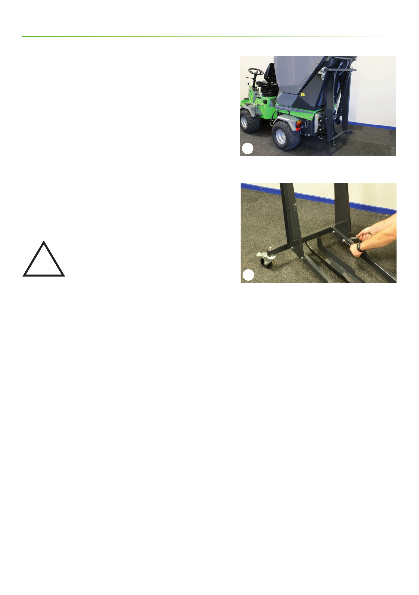
Attaching and detaching of the suction sweeper unit is quick
and easy with the special designed roller stand. The front
brushes and the collecting tank are dismounted directly on
the stand, which ensures the driver an easy handling and
a minimum storage room. With the Park Ranger 2150 the
changeover from one attachment to another is done in less
than 4 minutes - no tools required.
Additional Side Brush - Optional equipment
A hydraulically operated third brush increases the sweeping
path to 1660 mm and makes it easy to keep also hard
accessible angles and corners neat and clean.
Remote vac hose - Optional equipment
The remote vac hose is ideal for the cleaning of places with
dicult access like between parked bicycles, on basements
stairs etc. The 6 m long hose is kept on the top of the hopper
and is always within reach.
Contents
Introduction ....................................................................................2
Contents........................................................................................3
General information..............................................................................4
1.1 Safety.....................................................................................4
1.2 EU Declaration of Conformity.................................................................6
1.3 Technical data .............................................................................7
Operator´s Manual ...............................................................................8
2.1 Assembling the hopper frame ................................................................8
2.2 Assembly/Disassembly......................................................................9
2.3 Important before starting ..................................................................16
2.4 Start-Up .................................................................................17
2.5 Hopper discharge .........................................................................19
2.6 Adjustment...............................................................................20
Service and maintaince ..........................................................................23
3.1 Cleaning/replacing lter system and turbine ..................................................23
3.2 Maintenance .............................................................................24
3.3 Troubleshooting...........................................................................26
Conditions .....................................................................................29
4.1 Warranty.................................................................................29
4.2 Complaints ...............................................................................30
4.3 Disposal..................................................................................30
Wearing parts .................................................................................31
5.1 Wearing parts - Park Ranger 2150 suction sweeper .............................................31
Notes ........................................................................................33

1
2
3
4
4Operator´s Manual Park Ranger 2150 Suction sweeperOperator´s Manual Park Ranger 2150 Suction sweeper
1.1 Safety
Assembly
Check that the bonnet is closed and locked before
attaching the sweeper unit. (Picture 1)
Make sure that the hopper is attached correctly, and
that the locking handle is left in locked position.
(Picture 2)
Prevent people from standing close
to the suction sweeper
Make sure there is no one close to the
machine when it is in use.
Attention!
As it is articulated, the rear end of the
machine swings out when turning. Make
sure that no one is near the machine
while it is in use as there is a danger of
crushing.
Risk of crushing
Make sure no one gets their ngers
trapped when the hopper is lowered after
tipping.
Risk of impact when using the lever
Do not let go of the lever when the hopper
is lowered as that is dangerous. Keep a
good grip of the lever until the hopper is
on the machine. (Picture 3)
Reduce noise level and energy
consumption
In order to reduce both noise level and
energy consumption, it is recommended
to avoid excessive motor speeds.
Avoid damage to your hearing
Always wear approved ear protectors
when using the machine. (Picture 4)
General information
Close and lock the bonnet
Locked position
Lowering the hopper
Wear ear protectors
!
!
!
!
!
!

1Máx. 10°
5
Operator´s Manual Park Ranger 2150 Suction sweeperOperator´s Manual Park Ranger 2150 Suction sweeper
Avoid roll-overs
Do not drive the machine in a place where
it can slide, tip or roll. Do not drive on
slopes with an incline of more than 10°.
(Picture 1)
The hopper is tted with a load cell,
which is activated, when the hopper load
reaches 300 kg. When the alarm sounds,
the hopper must be emptied.
Attention!
The load cell must be checked daily,
before sweeping. (Refer to section 2.3.4)
The load cell must be calibrated each
month. (Refer to section 2.6.4)
Before emptying the hopper, make
sure that:
a. The machine is rmly placed on a level
surface and is not “angled”
b. That there is sucient space for the
open back cover.
The cab of the Park Ranger 2150 is approved as
a roll-over protection structure. (ROPS)
It is recommended that this cab is tted for
operation in areas with a high risk of
tipping.
General information
!
!
!
!
!
Do not drive on slopes with an incline of more than 10°

6Operator´s Manual Park Ranger 2150 Suction sweeperOperator´s Manual Park Ranger 2150 Suction sweeper
1.2 EU Declaration of Conformity
Manufacturer: Egholm A/S
Address: Transportvej 27 · DK-7620 Lemvig
Telephone: (+45) 97 81 12 05
hereby declares that
Machine: Suction sweeper 2150
Type: FS2150
· has been manufactured in conformity with the provisions of Machinery
Directive 2006/42/EU
· has been manufactured in conformity with the provisions of
Directive 2000/14/EU
and in accordance with
· DS/EN 13019 Machines for road surface cleaning – Safety requirements
The Park Ranger 2150 tted with the FH 2100 cab (ROPS approved)
· has been tested at the Danish Institute of Agricultural Sciences at Bygholm
in conformity with directive 86/298/EEC concerning rear mounted, roll-over
protection structures of narrow-track wheeled agricultural and forestry
tractors.
Place: Lemvig
Date:
Signature:
Knud Olsen, Senior Engineer
General information

7
Operator´s Manual Park Ranger 2150 Suction sweeperOperator´s Manual Park Ranger 2150 Suction sweeper
1.3 Technical data
General information
Dimensions
Suction sweeper, standard with two brushes:
Assembled: Storage dimensions:
Length(L) 2,900 mm 1,350 mm
Width (B) 1,200 mm 1,010 mm
Height without cab 1,850 mm 1,920 mm
Height with cab 1,935 mm
Height with remote vac hose 2,200 mm
Suction Sweeper Unit, with additional side brush:
Assembled: Storage dimensions:
Max. length (L): 3,550 mm 750 mm
Max. width (B): 1,660 mm 600 mm
Side Brush Height (H): 450 mm 450 mm
Technical data
Type FS2150
Sound power level, re Directive 2000/14/EU 107 Lwa
Hopper volume 450 litres
Max. weight in hopper 300 kg
Water tank volume 100 litres
Clearing width 1,200 mm
Clearing width with one side-brush 1,660 mm
Tipping height 1,300 mm
Ground clearance under vacumm nozzle 55 mm
Ground clearance below brushes 140 mm
Clearing area at 5-8 km/h 5,000-8,000 m2/h
Water capacity 1 water jet approx. 2½ hours
3 water jets approx. 1½ hours
Hydraulic oil Texaco Rando HDZ 46
or equivalent
Attention
Specications may change without notice.

1
2
8Operator´s Manual Park Ranger 2150 Suction sweeperOperator´s Manual Park Ranger 2150 Suction sweeper
Operator´s Manual
2.1 Assembling the hopper frame
The hopper frame is folded up and hung on the hopper on
delivery. Assembling the hopper frame:
1. Take the hopper frame down and unfold it. (Picture 1)
2) Put the frame together using the two bolts supplied.
(Picture 2)
Moving the hopper frame
The hopper frame can be transported on the suction
sweeper. Fold it down in reverse order and hang it on the
hopper.
Attention!
The hopper must never be emptied when
the hopper frame is hanging on the
suction sweeper!
Transporting the hopper frame on the hopper
Two bolts on the hopper frame
!

1
2
3
A B
B
C
9
Operator´s Manual Park Ranger 2150 Suction sweeperOperator´s Manual Park Ranger 2150 Suction sweeper
2.2 Assembly/Disassembly
Fittings of Standard Brushes
1. Turn the locking handle all the way to the left.
(Picture 1)
2. Approach the front brushes with the machine until the
two A-frames interlink.
3. Lift the A-frame using lever A on the left side of the
machine until the brushes are suspended freely above the
ground. (Picture 2)
4. Lock the front brushes on the A-frame by pushing the
lock handle all the way to the right.
5. Connect the two hydraulic hoses from the front brushes
with the B-outlets on the left side of the machine.
(Picture 2)
6. Fasten the hydraulic hoses with a rubber ring to a catch
under the footboard in order to ensure that the hoses lie
correctly over the guard. (Picture 3)
Operator´s Manual
A-frames Locking handle
Lever A, B, C B-outlets
Fasten with rubber ring

1
2
10 Operator´s Manual Park Ranger 2150 Suction sweeperOperator´s Manual Park Ranger 2150 Suction sweeper
2.2 Assembly/Disassembly - continued
Before tting the additional side brush
When the additional side brush is ordered together with
the suction sweeper unit, the front brushes will be
prepared for the extra brush upon delivery.
When the additional side brush is ordered separately, the
twin front brushes will have to be prepared for the extra
brush by means of an arm to be tted on the front brushes
before the rst use. Fit the arm as follows:
1. Remove the bolt on the right front brush. (Picture 1)
2. Screw ttings together. (Picture 1)
3. Mount the ttings for the spray jet with the bolt.
(Picture 2)
4. Tighten the bolt to 45 Nm.
5. The arm is now xed and ready for use.
Remove bolt-Fittings
Mount the ttings with the bolt
Operator´s Manual

1
2
3
11
Operator´s Manual Park Ranger 2150 Suction sweeperOperator´s Manual Park Ranger 2150 Suction sweeper
Fitting the side brush
1. Lower the side brush down into the arm (Picture 1)
and secure with safety split (A).
2. Fit the cylinder and secure with safety split (B).
(Picture 2)
3. Lead the hydraulic hoses along the right side of the
machine and connect with the E-outlets. (Picture 3)
Important! Before starting
The hydraulic hoses must be connected
to the E-outlets of the three-way-valve
before starting or there will be pressure in
the couplings.
Fitting the side brush Arm
Secure with safety split
E-outlet
!
Operator´s Manual

1
2
3
12 Operator´s Manual Park Ranger 2150 Suction sweeperOperator´s Manual Park Ranger 2150 Suction sweeper
Fitting the hopper
1. Check that the engine bonnet is locked before tting the
sweeper unit.
2. Back the machine up to the hopper, which is stored
on the roller stand, and stop the engine.
3. Push the roller stand with hopper over the bonnet
and leave approx. 5 cm of the hopper to project to
the rear.
4. Press down the lever, push the lock catch free from
the beard and lower the hopper slowly down over
the machine. (Picture 1)
Warning!
Avoid getting your ngers caught and
keep a rm grip of the lever when
lowering the hopper.
5. Release the roller stand and pull away.
6. Push the hopper forwards into place.
7. Make sure that the locking handle is left in locked
position - shake the hopper slightly to test a correct
t. (Picture 2)
8. Connect the 12 Volt plug on the right side of the
machine.
9. Fit the 2 hydraulic hoses to the D-outlet on the right side
of the machine. (Picture 3)
10. Connect the water hose. (Picture 3)
Lowering the hopper
Locked position 12 Volt plug
D-outlets Water hose
!
Operator´s Manual

1
2
3
13
Operator´s Manual Park Ranger 2150 Suction sweeperOperator´s Manual Park Ranger 2150 Suction sweeper
11. Attach the suction hose to the suction mouth.
(Picture 1)
12. When tting the sweeper unit with twin front brushes,
connect the two small hydraulic hoses to the C-outlets on
the rear chassis. (Picture 2)
13. If the sweeper unit is equipped with additional side
brush, lead the hydraulic hoses along the right side of the
machine and connect with the E-outlets. (Picture 3) Attach the suction hose to the suction mouth
C-outlets
E-outlets
Operator´s Manual

1
2
3
4
14 Operator´s Manual Park Ranger 2150 Suction sweeperOperator´s Manual Park Ranger 2150 Suction sweeper
Before tting the remote vac hose
When the remote vac hose is ordered together with the
suction sweeper unit, the hopper will be prepared for
the hose upon delivery.
When the remote vac hose is ordered separately, the
hopper will have to be prepared for the hose by means
of a support ring and a transport lock to be tted on
the hopper before the rst use. Fit the support ring
and the transport lock as follows:
Support ring
1. Dismount the top grating (Picture 2) by loosening
the four screws on the front of the grating.
2. Fit the support ring and screws in the holes on the
hopper. (Picture 1)
3. Fit the top grating again.
Transport lock
1. Put a nylon block on both ends of the transport
lock.
2. Fit the transport lock by pressing the nylon blocks into
the fourth row (from behind) of the top grating (hole in
the ball catch pointing forwards). (Picture 2)
3. The support ring and the transport lock now form
an integral part of the suction sweeper unit, and the
remote vac hose can be tted.
Fitting the remote vac hose
Fit the remote vac hose by lowering it down into the
hole on the top front side of the hopper. (Picture 3)
Working with the remote vac hose
Reduce the suction power and pull down the remote
vac hose from the storage case on the top of the
hopper. The remote vac hose is now ready for use.
(Picture 4)
Support ring Screws
4. Hole Transport lock Top grating
Fitting: Storage case Support ring
Remote vac hose in use
Operator´s Manual

1
2
3
15
Operator´s Manual Park Ranger 2150 Suction sweeperOperator´s Manual Park Ranger 2150 Suction sweeper
Transport of the remote vac hose
1. Start the suction sweeper unit and set the air ow to
the remote vac hose. (Page 17 - switch handle)
2. Enter the remote vac hose into the storage case and
let the hose be contracted by the vacuum.
3. Attach the rubber strap. (Picture 1)
4. Lock the transport lock. (Picture 1) If the remote vac
hose is ordered separately, the support ring and transport
lock will have to be tted before starting.
NB! When driving short distances, the vac hose can be
left uncontracted in the storage case. In that case beware
of the hose not getting caught in anything on the way.
Dismounting the suction sweeper unit
Like tting, just in reverse order.
DON’T FORGET when dismounting!
1. Disconnect the suction hose from the front brushes
and hook it on the ttings to the right below the
hopper opening. (Picture 2)
2. Remove the 12 Volt plug.
3. Disconnect the hydraulic hoses and the water hose -
suspend them around the suction hose to avoid them
getting jammed by the next tting. (Picture 3)
Warning
Make sure that all hydraulic and water
hoses have been disconnected and that
no hoses are caught in something when
driving away from the hopper!
Dismounting the additional side brush
Like tting, just in reverse order. (Page 11)
If sweeping is to be continued after having dismounted
the additional side brush, connect the two hydraulic
hoses in front of the brushes.
!
Rubber strap Transport lock
Fittings for suction hose
Storage of hydraulic and water hoses
Operator´s Manual

1
2
3
4
16 Operator´s Manual Park Ranger 2150 Suction sweeperOperator´s Manual Park Ranger 2150 Suction sweeper
2.3 Important before starting
1. Water lling
Filling the water tank before starting is important.
(Picture 1)
The suction sweeper unit comes standard with 3 jet
sprayers: one in the hopper and one on each of the
twin front brushes. (Picture 2 and 3)
The water capacity is enough for about 1.5 hours of
work when using all jet sprayers, or for about 2.5 hours
when using only the jet sprayer inside the hopper.
2. Control of turbine and lter
Check the turbine and the lter and remove possible
dirt. (Refer to paragraph 3.1.)
3. Adjustment of the brushes
In order to ensure the brushes a long lifetime it is
important that they are adjusted correctly, so that the
brushes do not apply too much pressure on the
ground. (Refer to paragraph 2.6.)
4. Load cell check
1. Plug the 12 v connector into the power output.
2. Turn the ignition to rst position.
3. Switch on the power output.
4. Pull on the wire at the rear of the hopper. (Picture 4)
The alarm will sound. If there is no alarm, check the
load cell.
Attention!
The suction sweeper unit must only be
used with fully functional load cell and
water pump in the hopper!
Stop the engine immediately in case of
unbalance or vibrations in the lter or
the turbine.
A level switch ensures that the water
pump stops automatically when the
water tank is empty.
Filling of water
Water jet in hopper
Water jets in front of the two standard brushes
Pre-start test - pull wire
!
!
!
Operator´s Manual

1
2
3
4
17
Operator´s Manual Park Ranger 2150 Suction sweeperOperator´s Manual Park Ranger 2150 Suction sweeper
2.4 Start-Up
1. Start the engine.
(Refer to the instruction manual for Park Ranger 2150
basic unit)
2. Switch the power output on, the water pump will
start and the overload alarm will sound if overload in
the hopper. (Picture 1)
3. If the two front-mounted jet sprayers are to be
activated, open the tap on the water hose on the right side
of the machine. (Picture 2)
4. Start the suction sweeper unit by pushing lever D
(on the right side of the machine) slowly upwards into
position 1. (Throttle hand lever being at least in half
throttle position). (Picture 2)
5. Activate the brushes by pushing lever B (on the left side
of the machine) into position 1. (Picture 3)
Attention!
Ensure the power output is always
switched on when sweeping, otherwise
the load cell and water pump will not
work.
Activating the additional side brush
If an additional side brush is tted, this is activated
automatically together with the twin front brushes when
pushing lever B into position 1. (Picture 3)
The additional side brush is operated with lever C on the
left side of the machine. (Picture 3)
Switching between the remote vac hose
and the front brushes
Turn the switch handle to redirect the ow between the
remote vac hose and the front brushes. (Picture 4)
!
Power outlet button
Lever D Tap for front-tted jet sprayers
Lever B Lever C
Switch handle
Operator´s Manual

1
2Máx. 10°
18 Operator´s Manual Park Ranger 2150 Suction sweeperOperator´s Manual Park Ranger 2150 Suction sweeper
Lever D Switch
Do not drive on slopes with an incline of more than 10°
Activating attachments from outside the
cab - only for the remote vac hose
1. Park the machine with the parking brake locked.
2. Press the button for conscious activating of
attachments while activating lever D. (Picture 1)
Avoid roll-overs
Do not drive the machine in a place where
it can slide, tip or roll. Do not drive on
slopes with an incline of more than 10°.
(Picture 2)
!
Operator´s Manual

1
2
3
4
19
Operator´s Manual Park Ranger 2150 Suction sweeperOperator´s Manual Park Ranger 2150 Suction sweeper
Lever D
Switch o power
Lever C
Hopper discharge
2.5 Hopper discharge
If the alarm sounds, empty the hopper
Hopper discharge follows either directly into a skip or
on the ground. The hopper has a discharge height of
130 cm.
Note!
Before hopper discharge make sure that:
a) The machine is horizontal and not ”broken”
b) There is enough space around the hopper to open the
tailgate and for the remote vac hose, if this is tted.
1. Stop the turbine by pushing lever D (on the right side of
the machine) into neutral position. (Picture 1)
2. Switch the power output o, hereby de-powering the
water pump and overload alarm. (Picture 2)
3. Drive to the nearest rubbish tip.
4. Hopper discharge follows by pushing lever C slowly
into position 1. (Picture 3)
5. When the hopper is discharged, push lever C
slowly into position 2 to lower the hopper. Make
sure that the hopper is fully lowered before releasing
lever C. (Picture 3)
6. Turn the engine o.
7. Move lever C once up and down to equalize the
hydraulic pressure, otherwise the alarm will sound
when power output is switched on. (Picture 3)
8. Start the engine.
9. Switch output power on before sweeping continues.
(Picture 2)
Empty the hopper every day after use.
Operator´s Manual

1
2
20
20 Operator´s Manual Park Ranger 2150 Suction sweeperOperator´s Manual Park Ranger 2150 Suction sweeper
Nose wheel for brush adjustment
Height adjustment Adjusting bolts
Important!
In order to avoid personal injury, never
open the tailgate before the turbine has
stopped! After switching o the turbine,
the turbine will keep running for approx.
15 sec.
Make sure that no person gets trapped
during hopper discharge.
Make sure that the hopper is fully
lowered after discharge!
2.6 Adjustment
1. Brush adjustment
Adjust the brushes by raising or lowering the nose wheel.
Set the brushes to touch the surface just enough to
obtain full sweeping width letting half of the brush ring in
contact with the surface. (Picture 1)
Basic Adjustment of the Suction Nozzle
Adjustment follows through the two bolts on the top of
the housing. The distance between the surface and the
suction nozzle should be approx. 25 mm. (Picture 2)
!
!
!
Operator´s Manual
Other manuals for Park Ranger 2150
18
Table of contents
Other Egholm Blower manuals