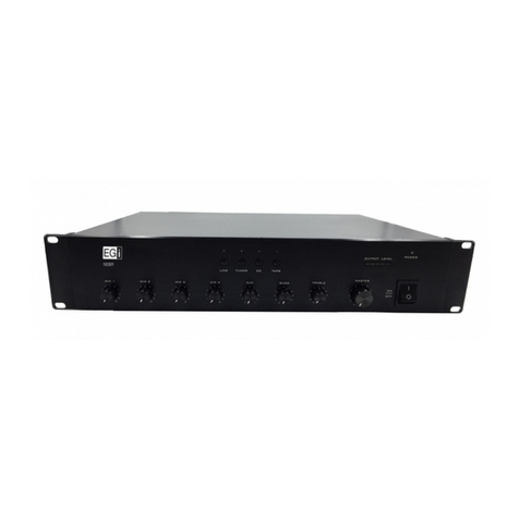
EGi Domos2 40426 User manual

009145 • 07/2018
Domos2
40426
–L L R +R
230 V~
3 4 5 6 7 8 9
2 0 1 – +L – +R
40291
L R ON COM AUTO
LN
25 W; 4 Ω
25 W; 4 Ω
1.5 W; 32 Ω1.5 W; 32 Ω1.5 W; 32 Ω1.5 W; 32 Ω1.5 W; 32 Ω
8
6
5
4
3
7
1
N L –L L R +R
2
L R ON COM AUTO
Especificaciones técnicas
40426 Etapa digital 2x25 W o 1x50 W con entrada PIN y Auto Line IN
es manual de instrucciones
Avda. Almozara, 79 • 50003 ZARAGOZA - España • T. +34 976 40 53 53 • F. +34 976 40 53 54 • e-mail: [email protected] • www.egiaudio.com
Funcionamiento
FUNCIONAMIENTO
IMPORTANTE: Antes de realizar ninguna conexión asegúrese de que la etapa de potencia no esté conectada a la red eléctrica.
La etapa de potencia 40426 necesita estar correctamente conectada antes de recibir alimentación, ya que se configura automáticamente tal y como se han realizado sus
conexiones al recibir red eléctrica. En caso de realizar cualquier cambio es necesario desactivar la red eléctrica, realizar el cambio y volver a conectar a la red eléctrica.
CONEXIONADO
Para comenzar a conectar la etapa de potencia 40426 siga las siguientes indicaciones.
AUDIO INPUT
Se pueden conectar 2 tipos de líneas de entrada (1) detectables manual o automáticamente.
• EGi PIN audio procedente de módulos EGi, con señales de audio de 3 V~ + señales de activación de +4.5 a 7 Vdc, para activar el encendido de la etapa
automáticamente a la vez que incorpora una señal de audio de valor suficiente para llevar líneas de cable paralelo o trenzado.
• LINE audio procedente de fuentes de sonido o módulos preamplificados, con señales de audio de 250 mV~ a 750 mV~ sin ningún tipo de activación.
POWER ON CONTROL
Para poder activar la etapa manual o automáticamente con señales preamplificadas, puede hacerlo de 2 maneras mediante el siguiente tipo de conexionado (2).
• ON/COM - Mediante estos 2 contactos normalmente abiertos (NA), podemos activar la etapa manualmente cerrando dicho contacto a través de un puente cerrado,
relés o interruptores normalmente abiertos (NA), para cerrarlos y activar la etapa en POWER ON. Mientras el contacto esté cerrado la etapa estará encendida (ON).
• AUTO/COM - Mediante estos 2 contactos normalmente abiertos (NA), podemos activar la etapa automáticamente cerrando dicho contacto a través de un
puente. Des esta forma, la etapa queda en estado de stand-by pero activando el sistema de detección de audio para encender la etapa cuando se detecte
una señal de audio. Dicha detección funciona y activa la etapa de potencia en el momento que hay una señal de audio mínima.
Durante el tiempo que haya música la etapa funcionará indefinidamente hasta que no aparezcan huecos de silencio de más de 30 segundos. A partir de ese
tiempo la etapa pasará a modo stand-by hasta que vuelva a detectar otra señal de audio.
NOTA: Existen pasajes en la música de intervalos similares, pero son muy puntuales y no importantes ya que la etapa volverá a activarse en el momento que
haya audio. Se recomienda tener especial cuidado en el cableado a utilizar entre la fuente musical y la etapa; ya que estos pueden inducir ruidos que nos
activen la etapa sin existir audio. Para ello, utilizar cable trenzado para líneas EGi PIN o líneas coaxiales apantalladas para entradas LINE IN.
115 ~ 230 V~; 50/60 Hz
66 W
25 + 25 W (estéreo) o 50 W (mono)
4 Ω(estéreo) o 2 Ω(mono)
Modo LINE IN: 33 KΩ
Modo PIN IN: 14 KΩ
Modo LINE IN: 500 - 750 mV
Modo PIN IN: 1 - 3 V
Tensión de alimentación
Consumo máximo
Potencia de salida de sonido
Impedancia mínima de salida
Impedancia de entrada
Sensibilidad de entrada
20 Hz ÷ 20 KHz
0.1%
En carril DIN o empotrable en caja EGi
ref. V11F + embellecedor ref. 40810
0.36
105 x 85.5 x 65
Respuesta en frecuencia (@ –3 dB)
Distorsión (THD)
Alojamiento
Peso (Kg.)
Dimensiones (mm)
Esquema de conexión
2 conductores
CONEXIÓN EN MODO MONO PUENTE
Desde 2 altavoces de 4 Ωen paralelo, hasta 16 altavoces de 32 Ω(total mín. 2 Ω).
EJEMPLO DE CONEXIÓN
A MANDOS EGi
EJEMPLO DE CONEXIÓN A FUENTES DE AUDIO EXTERNAS
CONEXIÓN EN MODO ESTÉREO
Desde 1 altavoz de 4 Ω, hasta 8 altavoces de 32 Ω
en paralelo (total mín. 4 Ω).
Salida de audio,
mezcladores, PC,
tablet, móvil, CD, DVD...
Cierre de contacto relé
o interruptor de encendido fijo
ON/COM (NA).
Cierre de contacto para activación
detección automática de audio
AUTO/COM.
3 conductores
1Entrada de audio externa (PIN o LINE IN).
2 Encendido externo opcional (ON fijo o AUTO automático).
3Led indicador de estado en reposo (STBY).
4 Led de encendido (ON).
5 Detección de conexión en modo mono puente.
6 Led de protección contra cortocircuito, sobrecarga o temperatura.
7 Salida de altavoces estéreo (–L +L; –R +R) y mono puente ( / ).
8 Entrada de alimentación o tensión de red.
SPEAKERS CONNECTION
Para detectar el modo de conexión realizado, primero conectar los altavoces en la salida SPEAKER CONNECTION (7) según el modo deseado, y luego alimentar
a la etapa con corriente eléctrica en la entrada de alimentación.
Antes de realizar cualquier cambio en el modo de conexión de los altavoces, recuerde quitar primero la alimentación de red, segundo modificar la conexión
de los altavoces y por último volver a conectar la alimentación de red (NO REALIZAR CAMBIOS DE CONEXIÓN EN ALTAVOCES MIENTRAS EXISTA
ALIMENTACIÓN DE RED).
• CONEXIÓN EN MODO ESTÉREO (– L + / – R +) - Conectando 2 líneas de altavoces obtenemos una conexión estéreo. Una en el canal izquierdo (Left) y otra
en el canal derecho (Right). De esta manera al recibir la corriente eléctrica, la etapa detectará que el funcionamiento es modo estéreo de 2x25 W y la impedancia
mínima por línea no debe ser inferior a 4 Ω.
• CONEXIÓN EN MODO MONO BRIDGE ( / ) - Conectando 1 línea de altavoces en modo puente, al recibir la corriente eléctrica, la etapa de potencia pasa
a modo mono sumando las entradas L y R, obteniendo un solo canal en modo puente de máximo de 1x50 W e impedancia mínima no inferior a 2 Ω.
Esta conexión tiene la peculiaridad de ir solo en las 2 tomas centrales de la regleta “conexiones de altavoces”, y no deben usarse las 2 conexiones laterales
de la misma.
NOTA: Para garantizar una correcta reproducción de audio y de frecuencias graves, ES OBLIGATORIO respetar las polaridades de los altavoces y de la etapa
en todo momento; tanto las conexiones en paralelo como las conexiones en serie.
TOMA DE RED ELÉCTRICA
Para conectar la red eléctrica asegúrese de que no existe corriente en los cables a conectar. Seguidamente, desatornille la tapita de protección (8), suelte la regleta
de conexión y conecte debidamente línea por línea el NEUTRO, la FASE y la TIERRA (evite dejar filamentos sueltos). Conecte de nuevo la regleta enchufable a la
etapa de potencia, oriente la salida de los cables hacia la parte inferior y cierre con la tapa protectora.
LEDS DE ESTADO
La finalidad de estos leds es informar al instalador o usuario del estado en que se encuentra la etapa de potencia.
• STBY (3) - Indica que existe alimentación de red continua en la fuente de alimentación interna y que, en caso de ser el único led encendido, la etapa se
encuentra en modo STAND-BY.
• POWER ON (4) - Indica que la etapa está activada y encendida en funcionamiento; bien por entrada PIN, bien por entrada LINE IN AUTO o por entrada LINE IN ON.
• MONO BRIDGE 50 W (5) - Indica que se ha conectado solo una línea de altavoces en modo PUENTE en el centro de las tomas centrales de la regleta
“conexiones de altavoces”, que la etapa se ha puesto en modo MONO PUENTE.
• PROTECTION (6) - Indica que durante el funcionamiento de la etapa se ha detectado una protección de la misma; bien por exceso de temperatura, cortocircuito
en las líneas de altavoces, impedancias inferiores a las recomendadas en las líneas de altavoces, derivaciones de estas líneas a tierra o por picos de armónicos
muy elevados.
SOBRE ESTE MANUAL
Todos los esfuerzos han sido realizados para asegurar que los contenidos
de este manual sean correctos y estén actualizados. Sin embargo, no es
posible garantizar la fidelidad de los contenidos, y el fabricante se reserva
el derecho de efectuar cambios sin previo aviso.
SOPORTE TÉCNICO
Si durante el uso de su sistema se encuentra con un problema, y no puede
solucionarlo consultando el manual, por favor, contacte con su instalador.
Puede también consultar la web www.egiaudio.com donde encontrará
información actualizada y otros recursos para dar solución a su problema.
INFORMACIÓN DE COPYRIGHT
Ninguna parte de este manual, incluyendo los productos o el software
descrito en él, podrá ser reproducido, transmitido, almacenado en sistemas
de recuperación, o traducido a ningún idioma en forma o medio alguno,
exceptuando documentación almacenada por el comprador para realizar
copias de seguridad, sin expreso consentimiento previo y por escrito del
fabricante.
Los productos y nombres corporativos que aparecen en este manual pueden
ser marcas registradas o copyright de sus respectivas compañías, y son
utilizadas aquí solo por motivos de identificación o explicativos y en beneficio
del dueño, sin intención de infringir dichas normas.
INSTRUCCIONES DE SEGURIDAD
Este sistema ha sido diseñado y fabricado para cumplir con los últimos
estándares de seguridad para equipos electrónicos en el ámbito
doméstico. Sin embargo, para asegurar un uso seguro de este producto,
es importante tener en cuenta las instrucciones indicadas en esta
documentación.
•Ningún producto de EGi deberá cubrirse con cualquier elemento que
dificulte su ventilación.
•No deben situarse sobre el aparato fuentes de llama desnuda tales como
velas encendidas o similares.
• No verter agua, no exponer a goteo o proyecciones de agua.
•Cortar el suministro de corriente antes de efectuar cualquier intervención
en la instalación.
•No exponga el producto a la acción directa del sol.
•No presionar con fuerza las partes móviles del producto.
•El usuario debe evitar cualquier intento de intervención o reparación del
producto y dirigirse únicamente a personal cualificado.
•Utilice únicamente los accesorios suministrados por EGi.
•EGi declina toda responsabilidad que derive del uso impropio del producto
o de un uso distinto de aquel para el que está destinado (ver el apartado
Garantía).
IMPORTANTE
Lea detenidamente estas "Instrucciones de seguridad" antes de utilizar cualquier producto EGi.
El signo de exclamación dentro de un triángulo indica la
existencia de importantes instrucciones de operación y
mantenimiento en la documentación que acompaña al producto
y la existencia de componentes internos cuyo reemplazo puede
afectar a la seguridad.
Aparato de Clase I.
El signo del rayo con la punta de flecha, alerta contra la presencia
de voltajes peligrosos. Para reducir el riesgo de choque eléctrico,
no retire la cubierta.
Los signos del rayo cerca de los terminales de salida del
amplificador alertan del riesgo de choque eléctrico en condiciones
normales de uso (terminales peligrosos al tacto). No toque dichos
terminales mientras el equipo esté encendido.
El presente producto no puede ser tratado como residuo
doméstico normal, sino que debe entregarse en el
correspondiente punto de recogida de equipos eléctricos y
electrónicos.
El producto es conforme a las Directivas Europeas que le aplican.
RESPONSABILIDAD
Debido al amplio espectro de servicios y dispositivos con los que interactúa el
sistema, el fabricante no puede responsabilizarse de fallos o funcionamientos
defectuosos o anómalos de dispositivos o sistemas no fabricados por EGi
conectados o usados por cualquier módulo de la serie.
DECLARACIÓN DE CONFORMIDAD
Electroacústica General Ibérica, S. A. con dirección en Avda. Almozara, 79 - 50003
Zaragoza (España), declara bajo su única responsabilidad que los equipos
descritos en este manual incorporan las funciones especificadas en cada caso
y son conformes con la normativa vigente: Directiva 2004 / 108 CE, relativa a
la compatibilidad electromagnética y Directiva de Baja Tensión 2006 / 95 / CE,
relativa a la seguridad de los receptores de baja tensión.
Debido a la política de mejora constante, EGi se reserva el derecho a
modificar en cualquier momento sus productos. Si bien se trata de
presentar la documentación actualizada, puede que los documentos y la
imagen proporcionada no coincidan con el producto adquirido.
Puede consultar las últimas versiones de documentación en
www.egiaudio.com
EGi no se responsabiliza de posibles errores en el texto o referencias.
Todas las marcas citadas están registradas por sus propietarios.
EGi garantiza sus fabricados electrónicos y electroacústicos contra cualquier defecto de fabricación que afecte a su funcionamiento durante 36 meses a
partir de la fecha de su producción (indicada en cada fabricado), comprometiéndose a reparar o reponer los módulos defectuosos cuyo fallo, siempre
a juicio de EGi, se deba a defecto de fabricación, sin cargos de repuestos.
Esta garantía no incluye gastos de envío de módulos, ni mano de obra de sustitución en la instalación de los citados módulos electrónicos y electroacústicos.
En ningún caso la garantía cubre los desperfectos o roturas de piezas embellecedoras (rejillas, embellecedores, carátulas, marquillos...).
Esta garantía se refiere únicamente al concepto de sustitución en fábrica de los módulos producidos por EGi, excluyéndose cualquier otra cobertura o
responsabilidad sobre el resto de materiales o el conjunto de la instalación puesta a disposición del usuario, pero que EGi no suministra ni ejecuta.
Por lo tanto no quedan cubiertas por esta garantía:
a. La instalación e interconexionado entre sus módulos.
b. Las consecuencias de abuso o mal uso del producto, incluyendo pero no limitado a:
b.1. No usar el producto para fines normales, o no seguir las instrucciones de EGi, para el correcto uso y mantenimiento del mismo.
b.2. La instalación o utilización de los productos de forma no concordante con las normas técnicas o de seguridad vigentes.
c. Las averías producidas por la incorrecta instalación de los módulos, o con cable que no sea el adecuado.
d. Las averías generadas por intervención de persona no autorizada por EGi.
e. Las consecuencias de mezcla con equipos de otro origen, así como adaptaciones, modificaciones, ajustes y/o tentativas de ajustes, irrespectivamente de que
ello haya sido efectuado de forma técnicamente correcta en principio, siempre que no exista expresa autorización por EGi.
f. Las consecuencias de accidentes, catástrofes naturales o cualquier causa ajena al control de EGi, incluyendo pero no limitado al rayo, agua y
disturbios públicos.
En todos estos casos excluidos de la garantía, y siempre que los módulos no sean juzgados como defectuosos por parte de EGi, su remitente deberá hacerse
cargo del importe total de la reparación, y caso de producirse visita de nuestros técnicos, su solicitante correrá con los gastos originados sin causa justificada
de garantía.
EGi se reserva el derecho a modificar en cualquier momento sus productos. Si bien se trata de presentar la documentación actualizada, puede que los documentos
y la imagen proporcionada no coincidan con el producto adquirido.
ATENCIÓN: Si Vd. observa algún problema en su instalación EGi nuestro Servicio de Atención al cliente le atenderá de 9 h. a 15 h.
Garantía
Información

009145 • 07/2018
Domos2
40426
–L L R +R
230 V~
3 4 5 6 7 8 9
2 0 1 – +L – +R
40291
L R ON COM AUTO
LN
25 W; 4 Ω
25 W; 4 Ω
1.5 W; 32 Ω1.5 W; 32 Ω1.5 W; 32 Ω1.5 W; 32 Ω1.5 W; 32 Ω
8
6
5
4
3
7
1
N L –L L R +R
2
L R ON COM AUTO
EGi guarantees its electronic and electroacoustic products against any manufacturing defect that affects its operation for 36 months from the production
date (indicated in every manufacture), taking the commitment of repairing or replacing the faulty modules which failure, always to the discretion of EGi, is
caused by a manufacturing defect, without any charge for spare parts.
This guarantee does not include charges for the shipping and handling of the modules, nor the labour charges for the replacement in the installation of the aforementioned
electronic and electroacoustic modules. The guarantee will not cover in any case the damages or breakings of the trimming pieces (lattices, trims, masks, frames...).
This guarantee refers only to the concept of replacement in factory of the modules produced by EGi, excluding any other cover or responsibility on the rest
of the materials or the whole of the installation that is put at the user disposal, but that is not supplied nor executed by EGi.
Therefore this guarantee does not cover:
a. The fitting up and the interconnection between the modules.
b. The results from the abuse or misuse of the product, including but not limited to:
b.1. Not using the product for usual purposes, or not following the instructions from EGi for the correct use and maintenance of the product.
b.2. The installation or use of the products in a way that is not concordant with the technical or security rules now in force.
c. The malfunctions caused by the wrong installation of the modules, or by an installation with inappropiate cables.
d. The malfunctions caused by the intervention of a person non-authorised by EGi.
e. The consequences of mixing with equipment from other sources, and also adaptations, modifications, adjustments and/or adjustment attempts, irrespectively
of those that have been performed in a technically correct way, provided that there is not an express authorisation by EGi.
f. The consequences of accidents, natural catastrophes or any cause beyond EGi control, including but not limited to lightning, water and public disturbances.
In all these cases that are excluded from the guarantee, and every time that the modules are not considered as faulty by EGi, the sender should take responsibility
of the full amount of the repair, and in the event of a visit from our technicians, the requesting person will bear the expenses originated without a cause justified
in the guarantee.
EGi reserves the right to modify its products at any time. Although it is about presenting updated documentation, the documents and the image provided may not
match the product purchased.
ATTENTION: If you notice any problem in your EGi installation, our Customer Support Service will attend you from 9 h. to 15 h (Central European Time).
Guarantee
Technical specifications
40426 Digital amplifier 2x25 W or 1x50 W with PIN input and Auto Line IN
en instruction manual
Av. Almozara, 79 • 50003 ZARAGOZA - Spain • T. +34 976 40 53 56 • F. +34 976 40 53 54 • e-mail: [email protected] • www.egiaudio.com
Function
115 ~ 230 V~; 50/60 Hz
66 W
25 + 25 W (stereo) or 50 W (mono)
4 Ω(stereo) or 2 Ω(mono)
LINE IN mode: 33 KΩ
PIN IN mode: 14 KΩ
LINE IN mode: 500 - 750 mV
PIN IN mode: 1 - 3 V
Power supply
Max. power consumption
Sound power output
Output impedance
Intput impedance
Input sensitivity
20 Hz ÷ 20 KHz
0.1%
DIN rail or recessed in EGi box ref.
V11F + trim ref. 40810
0.36
105 x 85.5 x 65
Frequency response (@ –3 dB)
Distortion (THD)
Housing
Weight (Kg)
Dimensions (mm)
1External audio input (PIN or LINE IN).
2 Optional external switching-on (fixed ON or automatic AUTO).
3Standby led (STBY).
4 Power on led (ON).
5 Detection of connection in mono bridge mode.
6 Short-circuit, overload or temperature protection LED.
7 Stereo speaker output (–L +L; –R +R) and mono bridge ( / ).
8 Mains power input.
OPERATING
IMPORTANT: Before making any connections, make sure that the power unit is not connected to the mains.
Power stage 40426 needs to be correctly connected before receiving power, since it is automatically configured as its connections have been made when receiving
electrical network. In case of making any change it is necessary to deactivate the electrical network, make the change and reconnect to the electrical network.
CONNECTION
To start connecting the 40426 power stage, follow the instructions below.
AUDIO INPUT
You can connect 2 types of input lines (1) detectable manually or automatically.
• EGi PIN audio from EGi modules, with 3 V~ audio signals + activation signals from +4.5 to 7 Vdc, to activate the start of the stage automatically while
incorporating an audio signal of sufficient value to carry Parallel or twisted cable lines.
• LINE audio from sound sources or preamplified modules, with audio signals from 250 mV~ to 750 mV~ without any activation.
POWER ON CONTROL
To activate the manual stage or automatically with pre-amplified signals, you can do it in 2 ways using the following type of connection (2).
• ON/COM - By means of these 2 normally open (NO) contacts, we can activate the stage manually by closing this contact through a closed bridge, relays or normally
open switches (NO), to close them and activate the stage in POWER ON. While the contact is closed the stage will be on (ON).
• AUTO/COM - By means of these 2 normally open contacts (NO), we can activate the stage automatically by closing this contact through a bridge. In this way, the
stage is in a stand-by state but activating the audio detection system to turn on the stage when an audio signal is detected. This detection works and activates
the power stage at the moment that there is a minimum audio signal.
During the time that there is music, the stage will work indefinitely until there are no hollows of silence of more than 30 seconds. After that time the stage will
go into stand-by mode until it detects another audio signal again.
NOTE: There are passages in music of similar intervals, but they are very punctual and not important since the stage will be activated again when there is
audio. It is recommended to take special care in the wiring to be used between the musical source and the stage; since these can induce noises that activate
the stage without audio. To do this, use twisted cable for EGi PIN lines or shielded coaxial lines for LINE IN inputs.
Wiring diagram
2 conductors
CONNECTION IN BRIDGE MONO MODE
From 2 speakers in parallel at 4 Ω, up to 16 speakers in parallel at 32 Ω(total minimum 2 Ω).
CONNECTION EXAMPLE
WITH EGi SOUND UNITS
CONNECTION EXAMPLE WITH AUDIO SOURCES
CONNECTION IN STEREO MODE
From 1 speaker at 4 Ω, up to 8 speakers in parallel at 32 Ω
(total minimum 4 Ω).
Audio OUT, mixers, PC,
tablet, mobile, CD, DVD...
Close contact relay
or switch on fixed ON/COM (NO).
Close contact for automatic activation
audio detection AUTO/COM.
3 conductors
SPEAKERS CONNECTION
To detect the connection mode made, first connect the speakers to the SPEAKER CONNECTION output (7) according to the desired mode, and then feed the stage
with electric current at the power input.
Before making any changes to the speaker connection mode, remember to first remove the mains supply, second modify the speaker connection and finally
reconnect the mains power (DO NOT MAKE CONNECTION CHANGES IN LOUDSPEAKERS WHILE POWER IS EXISTING OF NETWORK).
• CONNECTION IN STEREO MODE (– L + / – R +) - Connecting 2 speaker lines we obtain a stereo connection. One on the left channel (Left) and one on the right
channel (Right). In this way when receiving the electric current, the stage will detect that the operation is stereo mode of 2x25 W and the minimum impedance per
line should not be less than 4 Ω.
• CONNECTION IN MONO BRIDGE MODE ( / ) - Connecting 1 line of speakers in bridge mode, when the electric current is received, the power stage goes
into mono mode adding the L and R inputs, obtaining a single channel in bridge mode of maximum 1x50 W and minimum impedance not less than 2 Ω.
This connection has the peculiarity of going only in the 2 central sockets of the terminal strip "speaker connections", and the 2 lateral connections of the same
should not be used.
NOTE: To guarantee a correct reproduction of audio and of low frequencies, it is OBLIGATORY to respect the polarities of the speakers and the stage at all
times; both parallel connections and serial connections.
ELECTRIC POWER MAINS
To connect the electrical network, make sure that there is no current in the cables to be connected. Next, unscrew the protection cap (8), release the connection
strip and connect line by line NEUTRAL, PHASE and EARTH (avoid leaving loose filaments). Reconnect the plug-in terminal block to the power section, guide the
cable outlet to the bottom and close it with the protective cover.
STATUS LEDS
The purpose of these LEDs is to inform the installer or user of the state in which the power stage is located.
• STBY (3) - It indicates that there is continuous power supply in the internal power supply and that, if the only LED is on, the stage is in STAND-BY mode.
• POWER ON (4) - Indicates that the stage is activated and turned on during operation; either by PIN input, either by LINE IN AUTO input or by LINE IN ON input.
• MONO BRIDGE 50 W (5) - Indicates that only one line of speakers has been connected in BRIDGE mode in the center of the center sockets of the
"speaker connections" terminal, that the stage has been set to MONO BRIDGE mode.
• PROTECTION (6) - Indicates that during the operation of the stage a protection of the same has been detected; either due to excess temperature, short circuits
in loudspeaker lines, impedances lower than those recommended in loudspeaker lines, derivations of these lines to ground or high harmonic peaks.
ABOUT THIS MANUAL
We have taken all efforts to make the contents of this manual reliable and
updated. However, EGi does not guarantee the accuracy of the contents
which are subject to change without previous notice.
TECHNICAL SUPPORT
If, while using the system, you encounter a problem that cannot be solved
by consulting the manual, please contact the installer. You can also consult
the website www.egiaudio.com to find the latest information and other
resources to solve your problem.
COPYRIGHT INFORMATION
This manual in whole or in part, and any product or software described
herein, may not be reproduced, transmitted, saved in data recovery
systems, or translated into any language in any form or by any means, except
all documents saved by the user to make security copies; without the previous
written consent of the manufacturer.
All products or corporate names herein may (or not) be registered
trademarks or copyright of their respective companies and are used for
identification or explanatory reasons only, and in interest of the owner
without the intention of infringing any regulation or rule.
SAFETY INSTRUCTIONS
This system has been designed and manufactured in compliance with the
latest safety standards for household electronic equipment. However, to
ensure safe use of this product, it is important to follow the instructions given
in this documentation:
•No EGi product should be covered with anything that impedes ventilation.
•Do not place any sources of naked flame such as lighted candles or
similar elements on top of the device.
• Do not expose the device to poured, splashed or sprayed water.
•Disconnect the Mains supply before carrying out any work on the
installation.
•Do not expose the equipment to direct sunlight.
•Do not use excessive force when handling the product.
•The user should abstain from carrying out any alterations or repairs on
the product, reserving these actions for qualified personnel.
•Only use accessories supplied by EGi.
•EGi will not be held liable for any damage arising from misuse of the product
or usage other than what is was designed for (See Guarantee section).
An exclamation mark inside a triangle indicates important
operation and maintenance instructions and the existence of
components that may affect safety if replaced.
Class I device.
The lightening-shaped arrow warns of the presence of dangerous voltage.
To minimise the risk of electric shock, do not remove the cover.
The lightening signs near the amplifier output terminals warn
of the danger of electric shock in normal usage conditions
(Terminals dangerous to touch). Do not touch these terminals
while the device is in operation.
The present product can not be treated as normal domestic waste,
but must be handed over to the corresponding collection point
for electrical and electronic equipment.
This product is in accordance with the European Directives that apply.
LIABILITY
Due to the wide variety of services and devices the system interacts with, the
manufacturer cannot be held liable for failure or faulty operation of devices not
manufactured by EGi and connected or used by any module in the series.
DECLARATION OF CONFORMITY
Electroacústica General Ibérica, S. A. with registered address in Avda. Almozara, 79 -
50003 Zaragoza (Spain), declares under its sole responsibility that the equipment
described in this manual incorporates the functions specifies in each case and
complies with current regulations: Directive 2004 / 108 EC, regarding electromagnetic
compatibility and Low Voltage Directive 2006 / 95 / EC, regarding safety in low
voltage receivers.
Due to a policy of continuous improvement, EGi reserve the right to modify
their products at any time. Although every effort is made to present up to
date documentation, the documents and illustrations provided may not
coincide with the product purchased.
You can access the latest versions of documentation in:
www.egiaudio.com
EGi will not be held liable for any possible errors in the text or references.
All brands mentioned herein are registered with their owners.
IMPORTANT
Please read these "Safety instructions" carefully before using any EGi product.
Information
Table of contents
Languages:
Other EGi Amplifier manuals
