Eglo NOOSA 205481 User manual
NOOSA Smart Control Kit
Installation Manual
Use & Care Guide
Warranty Information
NOOSA SMART CONTROL KIT
No-Light Models:
LED Models:
205481 – 40” & 46” No-Light models
205482 – 52” No-Light models
205483 – 60” No-Light models
205484 – 40” & 46” LED models
205485 – 52” LED models
205486 – 60” LED models
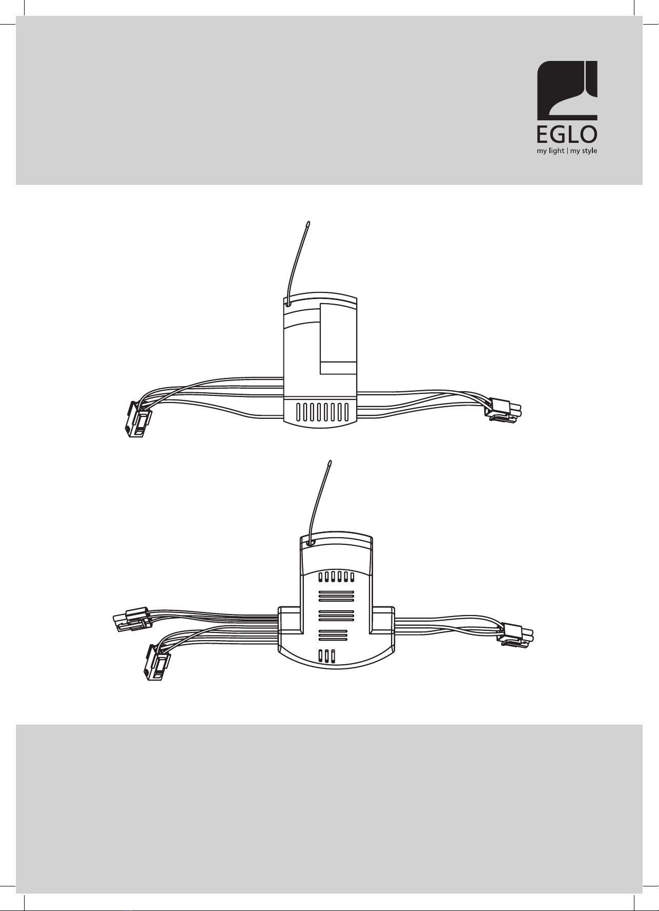
No-Light receiver
LED receiver
CONTENT:
NOOSA Smart Control Kit
FOR YOUR SAFETY: ………………………………………………………………………………………………….……..…… 4
SPECIFICATIONS: ………………………………………………………………………………………………………….……..…… 4
INSTALLATION: …………………………………………………………………………………………………………………………..……..…… 5
WIRING CONNECTIONS: ………………………………………………………………………………………………….…….………..…… 6
CODE LEARNING MODE: ………………………………………………………………………………………………….……………….……..…… 6
SETTING UP THE SMART CONTROL KIT:
NETWORK & ROUTER SETTINGS: …………………………………………………………………………………...………..…… 7
DOWNLOAD THE MY CONTROL APP: ……………………………………………………………………………………....…… 7
CONFIGURE YOUR IN-APP HOME: ………………………………………………………………………………….………..…… 7
CONNECTING MY CONTROL DEVICES: ………………………………………………………………..………….………..…… 7
OPERATING YOUR SMART CONTROL KIT:
OPERATING LIGHT FUNCTIONS: ……………………………………………………………………………………….……..…… 8
OPERATING FAN FUNCTIONS: ……………………………………………………………………………………………………… 8
OPERATING USING THE REMOTE CONTROL: ……………………………………………………………………….....…… 8
TROUBLESHOOTING: ………………………………………………………………………………………………………….....…… 8
WARRANTY:
WARRANTY CLAIMS ON INSTALLED PRODUCTS: ……………………………………………………………..……..…… 9
AUSTRALIAN CONSUMER LAW: ……………………………………………………………………………………………..…… 9
LIMITED REPAIR / REPLACEMENT WARRANTY: ……………………………………………………………….……..…… 9
WARRANTY TRANSFER: ………………………………………………………………………………………………….……...…… 9
WHAT IS NOT COVERED: …………………………………………………………………………………..…………………..…… 9
COMMERCIAL USE: ………………………………………………………………………………………………….……....……..… 10
WARRANTY CONDITIONS: ……………………………………………………………………………………………….…....…… 10
HOW TO MAKE A WARRANTY CLAIM: ………………………………………………………………………………………… 10
WARRANTY CLAIM FORM: …………………………………………………………………………………………….. 11
Smart control kit.
NOOSA Smart Control Kit
Do not dispose of electrical appliances as unsorted municipal waste, use separate collection facilities. Contact your local council for
more information regarding the collection systems available. If electrical appliances are disposed of in landfills or dumps, hazardous
substances can leak into the ground water and get into the food chain, damaging your health and well-being.
EGLO Lighting has a policy of continual product improvement and development, dimensions, hardware and designs may change to reflect
this policy. EGLO reserves the right to discontinue or change product specifications & designs at any time without notice and without
incurring obligations. The images including all features and specifications in this manual are for illustrative purposes only. Product details,
images & line drawings may vary depending on specific product models.

CONTENT:
NOOSA Smart Control Kit
FOR YOUR SAFETY: ………………………………………………………………………………………………….……..…… 4
SPECIFICATIONS: ………………………………………………………………………………………………………….……..…… 4
INSTALLATION: …………………………………………………………………………………………………………………………..……..…… 5
WIRING CONNECTIONS: ………………………………………………………………………………………………….…….………..…… 6
CODE LEARNING MODE: ………………………………………………………………………………………………….……………….……..…… 6
SETTING UP THE SMART CONTROL KIT:
NETWORK & ROUTER SETTINGS: …………………………………………………………………………………...………..…… 7
DOWNLOAD THE MY CONTROL APP: ……………………………………………………………………………………....…… 7
CONFIGURE YOUR IN-APP HOME: ………………………………………………………………………………….………..…… 7
CONNECTING MY CONTROL DEVICES: ………………………………………………………………..………….………..…… 7
OPERATING YOUR SMART CONTROL KIT:
OPERATING LIGHT FUNCTIONS: ……………………………………………………………………………………….……..…… 8
OPERATING FAN FUNCTIONS: ……………………………………………………………………………………………………… 8
OPERATING USING THE REMOTE CONTROL: ……………………………………………………………………….....…… 8
TROUBLESHOOTING: ………………………………………………………………………………………………………….....…… 8
WARRANTY:
WARRANTY CLAIMS ON INSTALLED PRODUCTS: ……………………………………………………………..……..…… 9
AUSTRALIAN CONSUMER LAW: ……………………………………………………………………………………………..…… 9
LIMITED REPAIR / REPLACEMENT WARRANTY: ……………………………………………………………….……..…… 9
WARRANTY TRANSFER: ………………………………………………………………………………………………….……...…… 9
WHAT IS NOT COVERED: …………………………………………………………………………………..…………………..…… 9
COMMERCIAL USE: ………………………………………………………………………………………………….……....……..… 10
WARRANTY CONDITIONS: ……………………………………………………………………………………………….…....…… 10
HOW TO MAKE A WARRANTY CLAIM: ………………………………………………………………………………………… 10
WARRANTY CLAIM FORM: …………………………………………………………………………………………….. 11
Smart control kit.
NOOSA Smart Control Kit
Thank you for purchasing your new EGLO Smart Control Kit.
To ensure a safe and successful installation, please make sure to read this manual, ensure
it is on hand for your installer to refer to, and keep in a safe place for future reference.

1. Please read this manual carefully before empng the assembly or installaon.
2. ALL electrical work should only be carried out by a suitably qualied and licenced electrical contractor. This smart control
kit MUST be installed ONLY by a suitably qualied and licenced electrical contractor.
3. Before commencing any electrical work, ensure the power is disconnected and/or the mains switched oat the circuit box
and ensure all pole isolaon of the power supply.
4. Ensure that the fan and the hanging bracket must be earthed.
5. This appliance is not intended for use by persons (including children) with reduced physical, sensory, or mental
capabilies, or lack of experience and knowledge, unless they have been given supervision or instrucon concerning the
use ofthe appliance by a person responsible for their safety.
6. Do NOT allow children to play with this appliance, and supervise children around electrical devises at all mes.
7. Use ONLY the EGLO controller supplied with your fan, or a suitable EGLO controller designed specically for your fan. Use
of non-EGLO or solid-state dimmer type controllers can reduce speedand airow, and can addionally damage your fan
motor which cannot be repaired, and which will not be covered under warranty.
8. All EGLO products are warranted to be free from defects in workmanship and materials provided the products are used
with a voltage supply within the range the product is designed to operate.
9. EGLO lighng will not be liable for any advice given to the consumer from any 3rd pares including suppliers, retailers &
electricians.
10. The important safeguards and instrucons in this manual are not designed to cover every possible condion or
circumstance. It is understoodthat common sense, cauon and care, are factors that cannot be built into the product, and
those operang and maintaining this product must supply these factors.
NOOSA Smart Control Kit
SPECIFICATIONS:
Model Input Weight (NW)
205481 (40/46” No-Light models) 220-240V~50Hz 145g
205482 (52” No-Light models) 220-240V~50Hz 145g
205483 (60” No-Light models) 220-240V~50Hz 145g
205484 (40/46” LED models) 220-240V~50Hz 170g
205485 (52” LED models) 220-240V~50Hz 170g
205486 (60” LED models) 220-240V~50Hz 170g
FOR YOUR SAFETY:
Fig. 3
NOOSA Smart Control Kit
Fig. 4
Fig. 5
Fig. 6
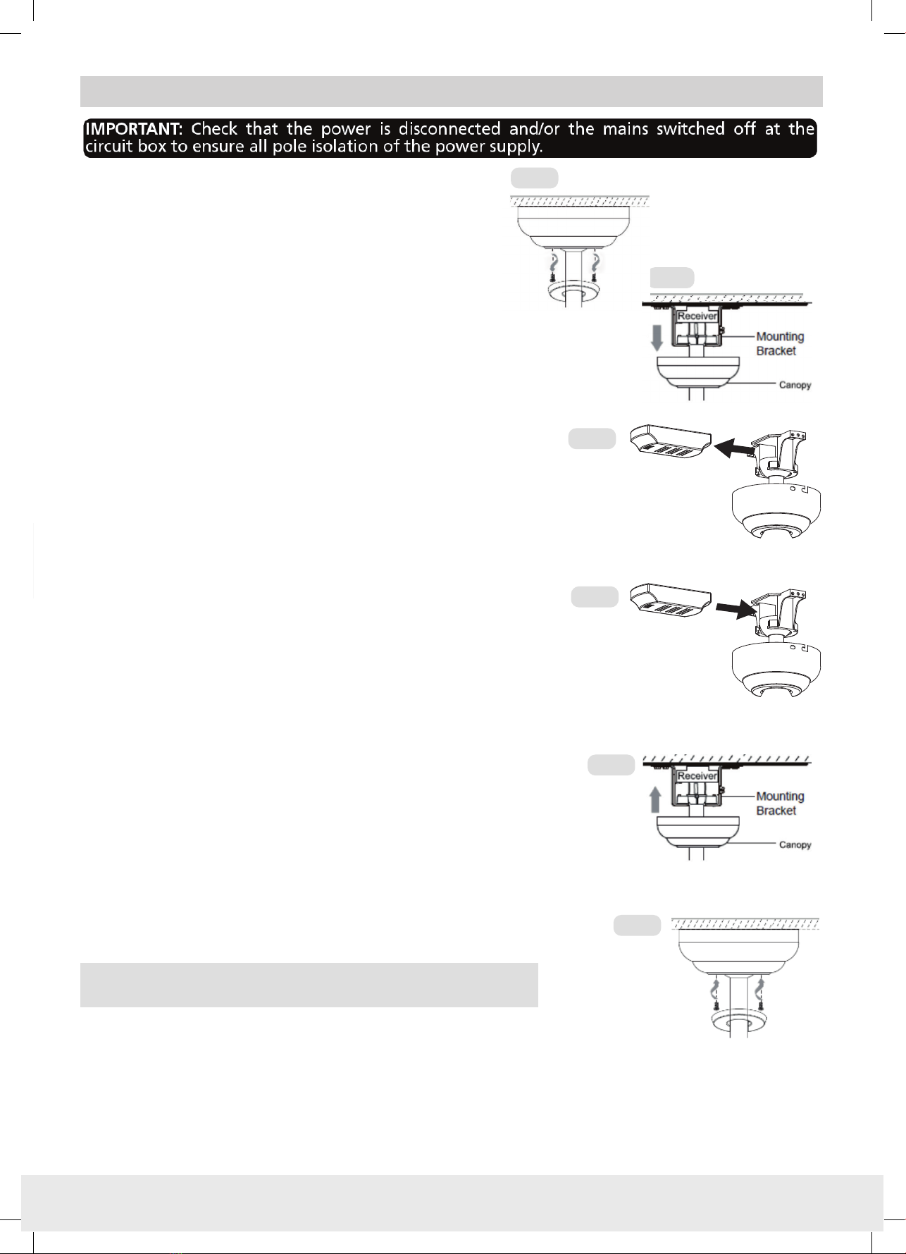
1. Lower the canopy ring; gently pry the ring away from
the canopy and let rest on motor housing. Refer Fig. 1.
2.
Twist the canopy an�-clockwise, and lower than canopy.
Refer Fig. 2.
3. Disconnect the plug connectors; between receiver and
terminal block, and the connectors between the receiver
and the fan. Refer ‘Wiring Connec�ons’.
4. Remove the receiver from the moun�ng bracket and
store. Refer Fig. 3.
5. Insert the new Smart Control Kit receiver into the moun�ng
bracket. Refer Fig. 4.
6. Connect the plug connectors; between receiver and terminal
block, and the connectors between the receiver and the fan.
Refer ‘Wiring Connec�ons’.
7. Loosely coil all cables and gently tuck them around the moun�ng
bracket. Raise the canopy up to the hanger bracket, and carefully
tuck cables inside the canopy as you slowly raise it to the ceiling.
Par�cular care must be given to ensure that no wires are damaged
during this step, especially the remote antenna. Refer Fig. 5.
8. Align the canopy over the screws, and twist to lock in posi�on, and
�ghten the 2 screws on the underside of the canopy.
9. Raise the canopy ring and gently push the canopy ring onto the
canopy. Refer Fig. 6.
Note: Models with light funcon have an addional plug connector for
the light connecon. Refer ‘Wiring Connecons’.
Fig. 1
Fig. 2
Loosen the 2 screws on the underside of the canopy. Refer Fig. 1,
INSTALLATION:
4
NOOSA Smart Control Kit
1. Please read this manual carefully before empng the assembly or installaon.
2. ALL electrical work should only be carried out by a suitably qualied and licenced electrical contractor. This smart control
kit MUST be installed ONLY by a suitably qualied and licenced electrical contractor.
3. Before commencing any electrical work, ensure the power is disconnected and/or the mains switched oat the circuit box
and ensure all pole isolaon of the power supply.
4. Ensure that the fan and the hanging bracket must be earthed.
5. This appliance is not intended for use by persons (including children) with reduced physical, sensory, or mental
capabilies, or lack of experience and knowledge, unless they have been given supervision or instrucon concerning the
use ofthe appliance by a person responsible for their safety.
6. Do NOT allow children to play with this appliance, and supervise children around electrical devises at all mes.
7. Use ONLY the EGLO controller supplied with your fan, or a suitable EGLO controller designed specically for your fan. Use
of non-EGLO or solid-state dimmer type controllers can reduce speedand airow, and can addionally damage your fan
motor which cannot be repaired, and which will not be covered under warranty.
8. All EGLO products are warranted to be free from defects in workmanship and materials provided the products are used
with a voltage supply within the range the product is designed to operate.
9. EGLO lighng will not be liable for any advice given to the consumer from any 3rd pares including suppliers, retailers &
electricians.
10. The important safeguards and instrucons in this manual are not designed to cover every possible condion or
circumstance. It is understoodthat common sense, cauon and care, are factors that cannot be built into the product, and
those operang and maintaining this product must supply these factors.
NOOSA Smart Control Kit
SPECIFICATIONS:
Model Input Weight (NW)
205481 (40/46” No-Light models) 220-240V~50Hz 145g
205482 (52” No-Light models) 220-240V~50Hz 145g
205483 (60” No-Light models) 220-240V~50Hz 145g
205484 (40/46” LED models) 220-240V~50Hz 170g
205485 (52” LED models) 220-240V~50Hz 170g
205486 (60” LED models) 220-240V~50Hz 170g
FOR YOUR SAFETY:
Fig. 3
NOOSA Smart Control Kit
Fig. 4
Fig. 5
Fig. 6
1. Lower the canopy ring; gently pry the ring away from
the canopy and let rest on motor housing. Refer Fig. 1.
2.
Twist the canopy an�-clockwise, and lower than canopy.
Refer Fig. 2.
3. Disconnect the plug connectors; between receiver and
terminal block, and the connectors between the receiver
and the fan. Refer ‘Wiring Connec�ons’.
4. Remove the receiver from the moun�ng bracket and
store. Refer Fig. 3.
5. Insert the new Smart Control Kit receiver into the moun�ng
bracket. Refer Fig. 4.
6. Connect the plug connectors; between receiver and terminal
block, and the connectors between the receiver and the fan.
Refer ‘Wiring Connec�ons’.
7. Loosely coil all cables and gently tuck them around the moun�ng
bracket. Raise the canopy up to the hanger bracket, and carefully
tuck cables inside the canopy as you slowly raise it to the ceiling.
Par�cular care must be given to ensure that no wires are damaged
during this step, especially the remote antenna. Refer Fig. 5.
8. Align the canopy over the screws, and twist to lock in posi�on, and
�ghten the 2 screws on the underside of the canopy.
9. Raise the canopy ring and gently push the canopy ring onto the
canopy. Refer Fig. 6.
Note: Models with light funcon have an addional plug connector for
the light connecon. Refer ‘Wiring Connecons’.
Fig. 1
Fig. 2
Loosen the 2 screws on the underside of the canopy. Refer Fig. 1,
INSTALLATION:
5
NOOSA Smart Control Kit

SINGLE FAN INSTALLATION:
Note: Blades must be aached or fan will not connue to operate.
1. Connect wiring and switch the power supply ON, the receiver will make a beep sound.
2. Within 30 secondsof the receiver being powered on (connected) aim the transmier towards the receiver and press “FAN
OFF” bun for 10 seconds or un a beep sound is heard meaning pairing/syncing has been successful.
Note: This must be done prior to ng canopy in place.
3. Operate and test.
4. Complete assembly of canopy.
MULTIPLE FAN INSTALLATION:
Note: Blades must be aached or fan will not connue to operate.
Important: The pairing/syncing of each fan and remote MUST be done with all other fans disconnected from the power supply.
1. Fan #1 - Connect wiring and switch the power supply ON, the receiver will make a beep sound.
2. Within 30 secondsof the receiver being powered on (connected) aim the transmier towards the receiver and press “FAN
OFF” bun for 10 seconds or un a beep sound is heard meaning pairing/syncing has been successful.
Note: This must be done prior to ng canopy in place.
3. Operate and test.
4. DO NOT complete assembly of fan #1. Disconnect fan #1 from the power supply, or unplug the receiver to disconnect from
terminal block.
5. Repeat steps 1-3 for each subsequent fan.
6. Only once all fans have been paired/synced and successful tested on separate remote control transmiers, can all fans then
be reconnected to power, and assembly of canopy completed.
NOOSA Smart Control Kit
Note: The plug connector and wires “for light” not included on non-light app control kits.
CODE LEARNING MODE:
LED model kit shown, No-Light model does not contain ‘Light Connecon’ wires.
ANT House Supply Wires
Active(L)
Earth(E)
Neutral(N)
Brown(L)
Blue(N)
Yellow/Green(E)
Brown(L)
Blue(N)
Yellow/Green(E)
Grey
Pink
Red
Yellow/Green(E)
Grey
Pink
Red
Brown
Blue
Red
Brown
Blue
Red
Light connection
(Light models only)
WIRING CONNECTIONS:
WARNING:
FOR YOUR SAFETY ALL ELECTRICAL CONNECTIONS MUST ONLY
BE UNDERTAKEN BY A QUALIFIED AND LICENSED ELECTRICIAN.
WARNING: For safe use of the fan, an all-pole MUST be incorporated into the d wiring in accordance with the wiring rules.
As outlined in clause 7.12.2 of AS/NZS 60335-1 for the minimum electrical safety of this standard.Please note warrantywill be void if
the is without a means for an all-pole incorporated in the rdance with the wiring rules.
A single pole isolaon switch must be also placed in the same room as the fan as per local wiring regulaons AS/NZS 3000, in accordance
with clause 2.3.2.2.1 & 4.13.1.3 of AS/NZS 3000.
Note: If there are two or more ceiling fans installed in the one locaon celling fan. This is
Note: The plug connector and wires “for light” not included on non-light app control kits.
NETWORK AND ROUTER SETTING:
Ensure you have a WiFi network, name and password that operates at 2.4Ghz to be compae with my control
products. Your IOS/Android device will need to be connected to this network when pairing or controlling your My Control
device. A minimum WiFi strength of 2 bars is necessary to connect and control your device.
DOWNLOAD THE SMART CONTROL APP:
1. Download the mycontrol App from App Store or Google Play or scan the
QR code.
2. Sign up to “create a new account”.
3. Follow the in-app prompt to complete the set up.
CONFIGURING YOUR ‘IN-APP’ HOME:
(Create a home enables the user to assign, allocate and share the devices easily)
Upon installaon of the mycontrol App, tap “Me” located at the bom right of the
screen and select “Home Management”, then “Create your home”. Follow the
prompts to complete your selecons and tap “Save”. Refer Fig 8
CONNECTING MY CONTROL DEVICES:
Follow the table and steps below to pair your devices.
1. Press and hold the “8H” buon on your remote control
for 2 to 3 seconds. When you hear a “beep” sound;
2. Open the App to the “Home” screen.
3. If your device have been discovered, go to (6).
4. From the App “Home” screen, tap “+” or “Add Device”. Refer Fig. 9.
5. "Select category "Small Home Appliances" > Fan (BLE+WiFi), and
tap “Add” when your device appears, and follow the prompts. Refer Fig 10.
6. Discovering devices..., “Add” when your device appears,
and follow the prompts.
7. Enter your 2.4GHz Winetwork name and Password
(previously set up) and tap “Next”. Refer Fig. 11.
8. Follow the prompt to complete the pairing process.
9. Once your device is successfully added, you can “re-name”
it and assign it to a room. Refer Fig. 12.
Note: Re-naming the device will enable beer control when linking
it with the compable devices.
NOOSA Smart Control Kit
Fig 12
Fig 9 Fig 10
Fig 11
Fig 8
SETTING UP THE SMART CONTROL KIT:
6
NOOSA Smart Control Kit

SINGLE FAN INSTALLATION:
Note: Blades must be aached or fan will not connue to operate.
1. Connect wiring and switch the power supply ON, the receiver will make a beep sound.
2. Within 30 secondsof the receiver being powered on (connected) aim the transmier towards the receiver and press “FAN
OFF” bun for 10 seconds or un a beep sound is heard meaning pairing/syncing has been successful.
Note: This must be done prior to ng canopy in place.
3. Operate and test.
4. Complete assembly of canopy.
MULTIPLE FAN INSTALLATION:
Note: Blades must be aached or fan will not connue to operate.
Important: The pairing/syncing of each fan and remote MUST be done with all other fans disconnected from the power supply.
1. Fan #1 - Connect wiring and switch the power supply ON, the receiver will make a beep sound.
2. Within 30 secondsof the receiver being powered on (connected) aim the transmier towards the receiver and press “FAN
OFF” bun for 10 seconds or un a beep sound is heard meaning pairing/syncing has been successful.
Note: This must be done prior to ng canopy in place.
3. Operate and test.
4. DO NOT complete assembly of fan #1. Disconnect fan #1 from the power supply, or unplug the receiver to disconnect from
terminal block.
5. Repeat steps 1-3 for each subsequent fan.
6. Only once all fans have been paired/synced and successful tested on separate remote control transmiers, can all fans then
be reconnected to power, and assembly of canopy completed.
NOOSA Smart Control Kit
Note: The plug connector and wires “for light” not included on non-light app control kits.
CODE LEARNING MODE:
LED model kit shown, No-Light model does not contain ‘Light Connecon’ wires.
ANT House Supply Wires
Active(L)
Earth(E)
Neutral(N)
Brown(L)
Blue(N)
Yellow/Green(E)
Brown(L)
Blue(N)
Yellow/Green(E)
Grey
Pink
Red
Yellow/Green(E)
Grey
Pink
Red
Brown
Blue
Red
Brown
Blue
Red
Light connection
(Light models only)
WIRING CONNECTIONS:
WARNING:
FOR YOUR SAFETY ALL ELECTRICAL CONNECTIONS MUST ONLY
BE UNDERTAKEN BY A QUALIFIED AND LICENSED ELECTRICIAN.
WARNING: For safe use of the fan, an all-pole MUST be incorporated into the d wiring in accordance with the wiring rules.
As outlined in clause 7.12.2 of AS/NZS 60335-1 for the minimum electrical safety of this standard. Pleasenotewarrantywill be void if
the is without a means for an all-pole incorporated in the rdance with the wiring rules.
A single pole isolaon switch must be also placed in the same room as the fan as per local wiring regulaons AS/NZS 3000, in accordance
with clause 2.3.2.2.1 & 4.13.1.3 of AS/NZS 3000.
Note: If there are two or more ceiling fans installed in the one locaon celling fan. This is
Note: The plug connector and wires “for light” not included on non-light app control kits.
NETWORK AND ROUTER SETTING:
Ensure you have a WiFi network, name and password that operates at 2.4Ghz to be compae with my control
products. Your IOS/Android device will need to be connected to this network when pairing or controlling your My Control
device. A minimum WiFi strength of 2 bars is necessary to connect and control your device.
DOWNLOAD THE SMART CONTROL APP:
1. Download the mycontrol App from App Store or Google Play or scan the
QR code.
2. Sign up to “create a new account”.
3. Follow the in-app prompt to complete the set up.
CONFIGURING YOUR ‘IN-APP’ HOME:
(Create a home enables the user to assign, allocate and share the devices easily)
Upon installaon of the mycontrol App, tap “Me” located at the bom right of the
screen and select “Home Management”, then “Create your home”. Follow the
prompts to complete your selecons and tap “Save”. Refer Fig 8
CONNECTING MY CONTROL DEVICES:
Follow the table and steps below to pair your devices.
1. Press and hold the “8H” buon on your remote control
for 2 to 3 seconds. When you hear a “beep” sound;
2. Open the App to the “Home” screen.
3. If your device have been discovered, go to (6).
4. From the App “Home” screen, tap “+” or “Add Device”. Refer Fig. 9.
5. "Select category "Small Home Appliances" > Fan (BLE+WiFi), and
tap “Add” when your device appears, and follow the prompts. Refer Fig 10.
6. Discovering devices..., “Add” when your device appears,
and follow the prompts.
7. Enter your 2.4GHz Winetwork name and Password
(previously set up) and tap “Next”. Refer Fig. 11.
8. Follow the prompt to complete the pairing process.
9. Once your device is successfully added, you can “re-name”
it and assign it to a room. Refer Fig. 12.
Note: Re-naming the device will enable beer control when linking
it with the compable devices.
NOOSA Smart Control Kit
Fig 12
Fig 9 Fig 10
Fig 11
Fig 8
SETTING UP THE SMART CONTROL KIT:
7
NOOSA Smart Control Kit
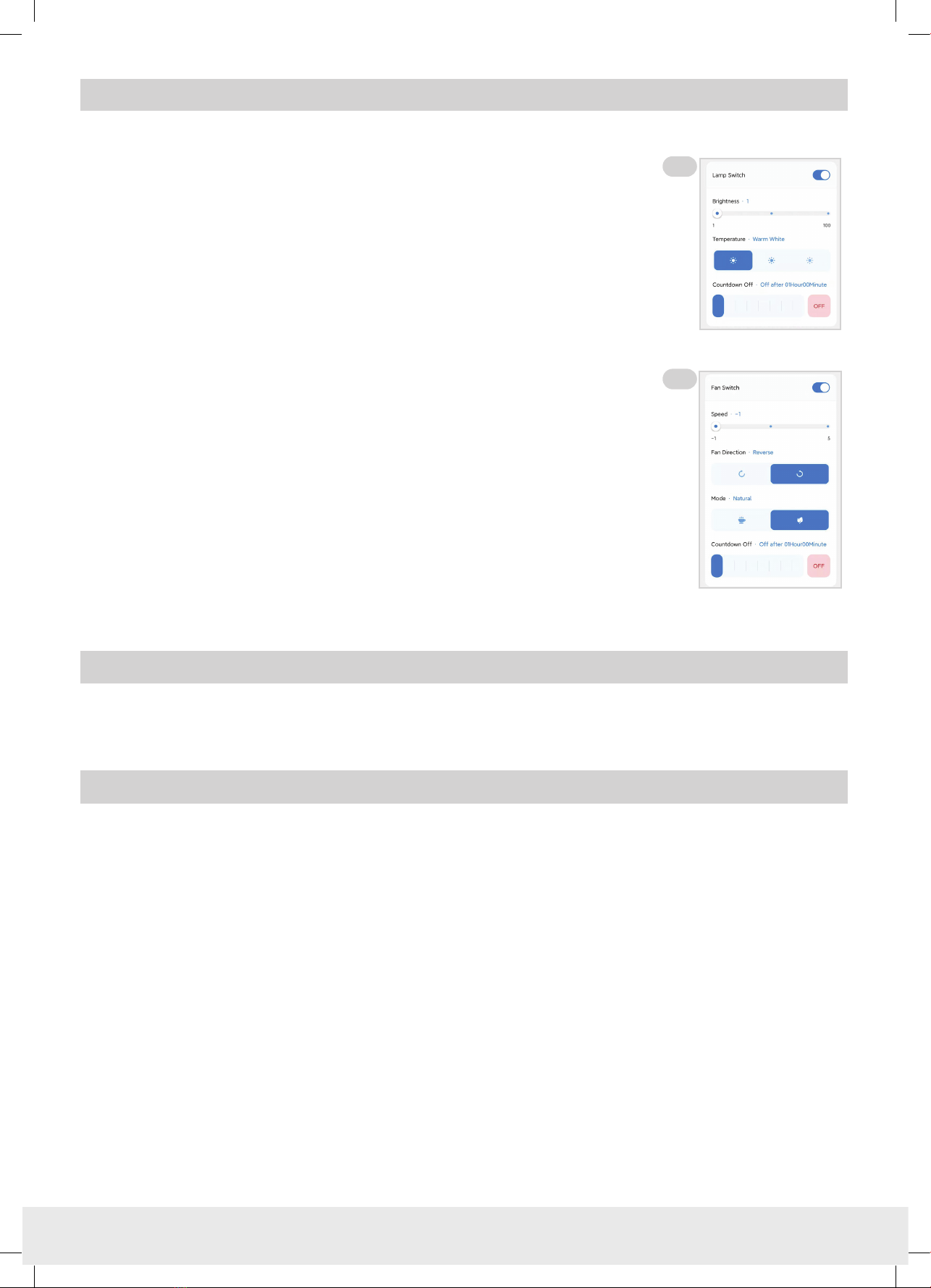
Opera�ng Light Func�ons: Refer Fig. 13.
Lamp Switch: Turns light On /
Brightness: Set brightness from 10% to 100%
Temperature: Switch between Warm White (3000k)
Neutral White (4000k)
Cool White (5000k)
Countdown : (Light Timer) Set desired period un light turns o
Opera�ng Fan Func�ons: Refer Fig. 14.
Fan Switch: Turns fan On /
Fan speed: ‘-1’ = Night Mode
‘1’ = Speed 1
‘2’ = Speed 2
‘3’ = Speed 3
‘4’ = Speed 4
‘5’ = Speed 5
Fan Direcon: Switch between‘Forward’ / ‘Reverse’ mode
Natural Breeze: Switch between ‘Normal’ / ‘Natural Breeze’ mode
Countdown : (Fan Timer) Set desired period un fanturns o
8NOOSA Smart Control Kit
OPERATING YOUR APP CONTROL KIT:
OPERATING USING THE REMOTE CONTROL:
Operang your fans via the remote control that came with the fan is the same as before. For detailed
instrucons about the funcons of the remote controls, refer to the Instrucon Manual supplied with the fan.
If you are experiencing problems while seng up or operang, please refer to the troubleshoong secon within
the My Control App.
TROUBLE SHOOTING
Fig 13
Fig 14
WARRANTY CLAIMS ON INSTALLED PRODUCTS:
1. AUSTRALIAN CONSUMER LAW:
The benefits given to you the consumer in this warranty document are in addition to your other rights and remedies under a law in relation
to the products to which this warranty document relates.
“YOUR CONSUMER RIGHTS”: “Our goods come with guarantees that cannot be excluded under the Australian Consumer Law. You are
entitled to a replacement or refund for a major failure and compensation for any other reasonably foreseeable loss or damage. You are
also entitled to have the goods repaired or replaced if the goods fail to be of acceptable quality and the failure does not amount to a
major failure.”
Subject to “Your Consumer Rights“ outlined above, but otherwise to the maximum extent permitted by law, EGLO will not be liable for
any consequential or indirect loss or damage suffered or incurred by you in relation to an EGLO product, including but not limited to loss
of use, loss or damage for business interruption, or profits.
2. LIMITED REPAIR / REPLACEMENT WARRANTY:
REPAIRS / REPLACEMENTS
EGLO products presented for repair may be replaced by refurbished goods of the same type rather than being repaired at the discretion
of EGLO. Refurbished parts may be used to repair the goods to proper order.
BALANCE OF WARRANTY
To the maximum extent permitted by law, any product replaced, repaired or refurbished by EGLO is covered only by the balance of the
warranty period remaining from the date of original purchase of the original EGLO product.
4. WARRANTY TRANSFER:
EGLO Lighting (EGLO) will not be liable for charges incurred by the consumer for rectification, de-installation or re-installa-
tion unless approved by EGLO management in writing prior to commencing work.
All claims are to be submitted to EGLO Warranty Department with a copy of the original purchase receipt, copy of receipt
from installation (inc electrical contractor licence number), and completed EGLO warranty claims form. Incomplete submis-
sion will result in delays processing your claim.
Any additional photos, videos or information that can be supplied at the time of submission, will help expedite your claim.
EGLO offers the purchaser a repair or replacement of the EGLO product in cases where the product fails due to defective
materials or workmanship, when installed and operated under normal domestic conditions, for a period of 1 year. Please
refer to the warranty period listed on each product to determine the warranty period which EGLO grants to the original
purchaser of the EGLO product. The warranty period begins from the date of purchase. Also, please refer to WHAT IS NOT
COVERED.
You must provide proof of purchase (such as the original dated purchase receipt/invoice) from an authorised EGLO reseller to
make a warranty claim. You must also provide a receipt from installation, including the electrical contractors licence number
- if an electrical licence number cannot be supplied, your claim will be denied. This warranty will not apply if the ceiling fan
is installed by anyone other than a qualified and licensed electrical contractor.
Resetting/Changing of DIP switches in connected remote controls is not covered by warranty and a service call fee WILL
apply.
Batteries (if supplied), are done so as a complimentary (free) item only, and are not covered by warranty.
If the ownership changes on the dwelling/premises where the EGLO product is installed, the balance of the warranty period
passes to the new owner provided the original proof of purchase (such as the original dated purchase receipt) from an
authorised EGLO retailer is retained by the new owner. In addition, proof of installation & licence number of the original
installing electrician must be retained.
8
NOOSA Smart Control Kit

Opera�ng Light Func�ons: Refer Fig. 13.
Lamp Switch: Turns light On /
Brightness: Set brightness from 10% to 100%
Temperature: Switch between Warm White (3000k)
Neutral White (4000k)
Cool White (5000k)
Countdown : (Light Timer) Set desired period un light turns o
Opera�ng Fan Func�ons: Refer Fig. 14.
Fan Switch: Turns fan On /
Fan speed: ‘-1’ = Night Mode
‘1’ = Speed 1
‘2’ = Speed 2
‘3’ = Speed 3
‘4’ = Speed 4
‘5’ = Speed 5
Fan Direcon: Switch between‘Forward’ / ‘Reverse’ mode
Natural Breeze: Switch between ‘Normal’ / ‘Natural Breeze’ mode
Countdown : (Fan Timer) Set desired period un fanturns o
8NOOSA Smart Control Kit
OPERATING YOUR APP CONTROL KIT:
OPERATING USING THE REMOTE CONTROL:
Operang your fans via the remote control that came with the fan is the same as before. For detailed
instrucons about the funcons of the remote controls, refer to the Instrucon Manual supplied with the fan.
If you are experiencing problems while seng up or operang, please refer to the troubleshoong secon within
the My Control App.
TROUBLE SHOOTING
Fig 13
Fig 14
WARRANTY CLAIMS ON INSTALLED PRODUCTS:
1. AUSTRALIAN CONSUMER LAW:
The benefits given to you the consumer in this warranty document are in addition to your other rights and remedies under a law in relation
to the products to which this warranty document relates.
“YOUR CONSUMER RIGHTS”: “Our goods come with guarantees that cannot be excluded under the Australian Consumer Law. You are
entitled to a replacement or refund for a major failure and compensation for any other reasonably foreseeable loss or damage. You are
also entitled to have the goods repaired or replaced if the goods fail to be of acceptable quality and the failure does not amount to a
major failure.”
Subject to “Your Consumer Rights“ outlined above, but otherwise to the maximum extent permitted by law, EGLO will not be liable for
any consequential or indirect loss or damage suffered or incurred by you in relation to an EGLO product, including but not limited to loss
of use, loss or damage for business interruption, or profits.
2. LIMITED REPAIR / REPLACEMENT WARRANTY:
REPAIRS / REPLACEMENTS
EGLO products presented for repair may be replaced by refurbished goods of the same type rather than being repaired at the discretion
of EGLO. Refurbished parts may be used to repair the goods to proper order.
BALANCE OF WARRANTY
To the maximum extent permitted by law, any product replaced, repaired or refurbished by EGLO is covered only by the balance of the
warranty period remaining from the date of original purchase of the original EGLO product.
4. WARRANTY TRANSFER:
EGLO Lighting (EGLO) will not be liable for charges incurred by the consumer for rectification, de-installation or re-installa-
tion unless approved by EGLO management in writing prior to commencing work.
All claims are to be submitted to EGLO Warranty Department with a copy of the original purchase receipt, copy of receipt
from installation (inc electrical contractor licence number), and completed EGLO warranty claims form. Incomplete submis-
sion will result in delays processing your claim.
Any additional photos, videos or information that can be supplied at the time of submission, will help expedite your claim.
EGLO offers the purchaser a repair or replacement of the EGLO product in cases where the product fails due to defective
materials or workmanship, when installed and operated under normal domestic conditions, for a period of 1 year. Please
refer to the warranty period listed on each product to determine the warranty period which EGLO grants to the original
purchaser of the EGLO product. The warranty period begins from the date of purchase. Also, please refer to WHAT IS NOT
COVERED.
You must provide proof of purchase (such as the original dated purchase receipt/invoice) from an authorised EGLO reseller to
make a warranty claim. You must also provide a receipt from installation, including the electrical contractors licence number
- if an electrical licence number cannot be supplied, your claim will be denied. This warranty will not apply if the ceiling fan
is installed by anyone other than a qualified and licensed electrical contractor.
Resetting/Changing of DIP switches in connected remote controls is not covered by warranty and a service call fee WILL
apply.
Batteries (if supplied), are done so as a complimentary (free) item only, and are not covered by warranty.
If the ownership changes on the dwelling/premises where the EGLO product is installed, the balance of the warranty period
passes to the new owner provided the original proof of purchase (such as the original dated purchase receipt) from an
authorised EGLO retailer is retained by the new owner. In addition, proof of installation & licence number of the original
installing electrician must be retained.
9
NOOSA Smart Control Kit

6. COMMERCIAL USE:
EGLO products which are specifically designed for commercial use are designated as Commercial Use Products on the product packaging.
All other EGLO products are designed for domestic use only.
This product is not designed or intended for industrial or commercial use.
WARRANTY CONDITIONS:
HOW TO MAKE A WARRANTY CLAIM:
Please return the faulty EGLO product together with a copy of the proof of purchase, and if required, a certificate of compliance for the
installation of the product by the licensed electrician who installed the product, to the authorised EGLO retailer where the product was
purchased. To the maximum extent permitted by law, the customer must bear the costs and expenses of claiming under this warranty,
including but not limited to the cost incurred in freight, postage, handling, travel, dismantling or reinstalling the product.
5. WHAT IS NOT COVERED:
Subject to “Your Consumer Rights“, but otherwise to the maximum extent permitted by law, the EGLO warranties provided
in this docu-ment will not cover the following:
1. EGLO products that are not purchased from an authorised dealer in Australia and installed in Australia.
2. Where installation was not carried out by a qualified and licensed electrical contractor or where a valid Electrical Safety
Certificate cannot be presented.
3. EGLO products not installed in accordance with the product’s installation instructions for use and/or specifications.
4. EGLO products not operated in accordance with the instructions for use, or specifications.
5. EGLO products that have been modified in any manner.
6. Defect, damage, or failure to a EGLO product resulting from misuse, accident, neglect, abuse, tampering, modifications
or unauthorised repairs of any kind by any person.
7. Damages not caused by a fault in the EGLO product materials or workmanship.
8. Defect, damage, or failure to an EGLO product resulting from any acts of God, including damage from lightning, power
grid fluctuations, or power surges.
9. Replacement of batteries supplied with certain products.
10. Damage caused by alternative power systems. (for example: ‘off grid’ etc.)
• This warranty is for 240V 50Hz products originally purchased in, and installed in Australia ONLY.
•Installation must be performed by a qualified and licensed electrician. The warranty will not apply if the product is installed
by other than a qualified and licensed electrician.
• Problems arising from incorrect installation are not covered by warranty.
•The cost of repairs and/or service call arising from incorrect installation, not due to faulty material or workmanship in
accordance with the EGLO warranty, will be payable by the purchaser.
• This warranty is only valid for appliances used according to the manufacturer’s instructions.
• This warranty is only valid for remote controls connected/paired to EGLO AC ceiling fans.
•The manufacturer does not accept liability for any direct or consequential damage, loss or other expense arising from
misuse or incorrect installation and operation of the appliance.
• Warranty will only be provided where proof of qualified electrical installation is provided. E.g. Electrical Safety Certificate.
•Warranty will not be provided if installation is without an all-pole disconnection incorporated in the fixed wiring in accor-
dance with the wiring rules.
IN THE CASE OF MISSING ACCESSORIES OR PARTS, PLEASE CONTACT EGLO CUSTOMER SERVICE BEFORE COMMENCING
INSTALLATION OF THE PRODUCT. IF YOUR PRODUCT IS DEFECTIVE OR EXCESSIVELY NOISY, PLEASE FIRST REFER TO THE TROU-
BLE SHOOTING SECTION OF THIS MANUAL AND PERFORM ALL CHECKS, AND THEN CONTACT EGLO CUSTOMER SERVICE
BEFORE THE ELECTRICIAN LEAVES THE RESIDENCE WHERE THE INSTALLATION IS TAKING PLACE.
10
NOOSA Smart Control Kit

6. COMMERCIAL USE:
EGLO products which are specifically designed for commercial use are designated as Commercial Use Products on the product packaging.
All other EGLO products are designed for domestic use only.
This product is not designed or intended for industrial or commercial use.
WARRANTY CONDITIONS:
HOW TO MAKE A WARRANTY CLAIM:
Please return the faulty EGLO product together with a copy of the proof of purchase, and if required, a certificate of compliance for the
installation of the product by the licensed electrician who installed the product, to the authorised EGLO retailer where the product was
purchased. To the maximum extent permitted by law, the customer must bear the costs and expenses of claiming under this warranty,
including but not limited to the cost incurred in freight, postage, handling, travel, dismantling or reinstalling the product.
5. WHAT IS NOT COVERED:
Subject to “Your Consumer Rights“, but otherwise to the maximum extent permitted by law, the EGLO warranties provided
in this docu-ment will not cover the following:
1. EGLO products that are not purchased from an authorised dealer in Australia and installed in Australia.
2. Where installation was not carried out by a qualified and licensed electrical contractor or where a valid Electrical Safety
Certificate cannot be presented.
3. EGLO products not installed in accordance with the product’s installation instructions for use and/or specifications.
4. EGLO products not operated in accordance with the instructions for use, or specifications.
5. EGLO products that have been modified in any manner.
6. Defect, damage, or failure to a EGLO product resulting from misuse, accident, neglect, abuse, tampering, modifications
or unauthorised repairs of any kind by any person.
7. Damages not caused by a fault in the EGLO product materials or workmanship.
8. Defect, damage, or failure to an EGLO product resulting from any acts of God, including damage from lightning, power
grid fluctuations, or power surges.
9. Replacement of batteries supplied with certain products.
10. Damage caused by alternative power systems. (for example: ‘off grid’ etc.)
• This warranty is for 240V 50Hz products originally purchased in, and installed in Australia ONLY.
•Installation must be performed by a qualified and licensed electrician. The warranty will not apply if the product is installed
by other than a qualified and licensed electrician.
• Problems arising from incorrect installation are not covered by warranty.
•The cost of repairs and/or service call arising from incorrect installation, not due to faulty material or workmanship in
accordance with the EGLO warranty, will be payable by the purchaser.
• This warranty is only valid for appliances used according to the manufacturer’s instructions.
• This warranty is only valid for remote controls connected/paired to EGLO AC ceiling fans.
•The manufacturer does not accept liability for any direct or consequential damage, loss or other expense arising from
misuse or incorrect installation and operation of the appliance.
• Warranty will only be provided where proof of qualified electrical installation is provided. E.g. Electrical Safety Certificate.
•Warranty will not be provided if installation is without an all-pole disconnection incorporated in the fixed wiring in accor-
dance with the wiring rules.
IN THE CASE OF MISSING ACCESSORIES OR PARTS, PLEASE CONTACT EGLO CUSTOMER SERVICE BEFORE COMMENCING
INSTALLATION OF THE PRODUCT. IF YOUR PRODUCT IS DEFECTIVE OR EXCESSIVELY NOISY, PLEASE FIRST REFER TO THE TROU-
BLE SHOOTING SECTION OF THIS MANUAL AND PERFORM ALL CHECKS, AND THEN CONTACT EGLO CUSTOMER SERVICE
BEFORE THE ELECTRICIAN LEAVES THE RESIDENCE WHERE THE INSTALLATION IS TAKING PLACE.
CHECKLIST - Have you supplied?
Receipt of purchase:Yes No
Receipt of installa�on/electrical safety cer�ficate: Yes No
photos / videos that may help fast track claim: Yes No
CUSTOMER DETAILS
Name:
Day�me Phone/Mobile:
Email:
WARRANTY CLAIM FORM Warranty Claim No.:
(EGLO Office Use Only)
INSTALLATION DETAILS
Electrician Business Name:
Electrician Name: Electrician Licence No.:
Installa�on Date: Electrician Phone/Mobile:
Electrician Email:
PRODUCT DETAILS
Series Name: Model Number:
Remote Control Accessory: Yes No Remote Model No.:
DC Wall Control Accessory: Yes No DC Wall Control Model No:
Fault Details:
To help us assist you with your claim, please complete the enclosed warranty form in full.
STORE PURCHASED FROM
Store Name:
Date of Purchase:
ADDRESS WHERE PRODUCT IS INSTALLED
Address:
Suburb/Town: State: Postcode:
I confirm that I have an isola�on switch installed for EACH of the ceiling fan(s) associated with this Warranty Claim. I understand that
my claim cannot be processed if an isola�on switch is not installed.
Please email this form, together with copy of your purchase receipt & electricians' invoice to:
EGLO LIGHTING AUSTRALIA
warranty@egloligh�ng.com.au
For assistance with your claim please phone:
1800 254 448
11
NOOSA Smart Control Kit

NOOSA Smart Control Kit
EGLO LIGHTING AUSTRALIA
5/339 Archerfield Road
Richlands
Queensland 4077
www.eglo.com.au
This manual suits for next models
5
Table of contents
Popular Controllers manuals by other brands

Cooper
Cooper WaveLinx Wired ILS-SCMA0401-1 installation instructions

Divebiss
Divebiss HEC-P6 Series user manual

DK System
DK System EKOSter 420 instructions

inVENTer
inVENTer ZR10-D Installation and operating instructions

Soundbeam
Soundbeam 2 Handbook

Lighthouse Worldwide Solutions
Lighthouse Worldwide Solutions REMOTE ActiveCount installation guide


Mellanox Technologies
Mellanox Technologies MUA9402E-2SF-100 Hardware user manual

Honeywell
Honeywell Pressuretrol L404 Series manual

Phoenix Contact
Phoenix Contact INTERBUS quick start guide

Nuvo
Nuvo Essentia BTicino NV-E6DS-BT manual

LOVATO ELECTRIC
LOVATO ELECTRIC ATL10 manual

Computherm
Computherm Q10Z operating instructions