Egress System HRX 5000 User manual

HRX 5000
Technical Manual
Version 1.2

HRX5000 Technical Manual V1.2Page 1 of 18
Contents:
Specification.....................................................................................................2
Connectors ......................................................................................................5
RS-485 Network Connectors (J6 and J7).....................................................5
RS-232 to Printer (J19) ................................................................................6
RS-232 to PC (J8)........................................................................................7
TCP/IP..........................................................................................................8
Power (J21)..................................................................................................9
Fire Alarm Input (J20).................................................................................10
Relays (J12, J15) .......................................................................................11
Remote Readers (J13, J16).......................................................................12
Remote Door Inputs (J14, J17)..................................................................13
Modem (J3)................................................................................................14
Access Control...............................................................................................15
Fire Alarm Interaction.................................................................................16
Bells...............................................................................................................16
Fire Alarm Printer...........................................................................................16
Issue History..................................................................................................18
HRX5000 Technical Manual V1.2Page 2 of 18
Specification
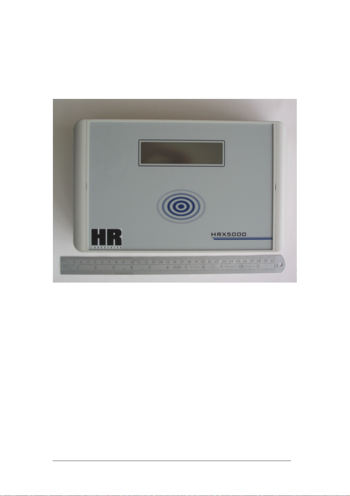
The HRX 5000 is a Proximity card reading terminal with TCP/IP connection,
Fire Alarm printout, Access Control for 2 doors and optional internal Modem.

HRX5000 Technical Manual V1.2Page 3 of 18
Dimensions: 280mm (W) X 170mm (H) X 60mm (D)
Display: 16 X 2 Large character LCD with LED Backlight
Display area: 100mm X 25mm
Clockings: 15,000 in circular buffer
Employees:25 to 1,000, remotely upgradeable
Firmware: Flash memory upgradeable over TCP/IP
Configuration: 1 Master, up to 15 Slaves
Reader: Type: 125KHz HID type
Range: 80mm (ISO & Clamshell badges)
30mm (Keyfobs)
Battery Backup: Lithium battery for data and clock for 3 years
Enclosure: Material –Flame retardant ABS
IP rating –standard purchase is unsealed
Optionally sealed to IP66 (hosedown)
Weight: 1 KG.
UPS: Optional external

HRX5000 Technical Manual V1.2Page 4 of 18
Connections: Power 9-12v DC 350mA to 500mA
TCP/IP 10/100 Base-T
RS/232 Second, alternative, PC connection
RS485 Slave clocks. 2 connectors for buss
RS232 Fire Alarm printer
Digital IN Fire Alarm Panel
Remote Reader A8 core up to 50 metres
Relay ASPCO up to 250V 0.5A
Door Ajar AFrom magnetic contact
Egress AFrom egress button
Remote Reader B8 core up to 50 metres
Relay B SPCO up to 250V 0.5A
Door Ajar BFrom magnetic contact
Egress B From egress button
Modem Line connector
Modem Options: Internal PSTN type
Internal GSM type (data SIMM contract required)
Power Supply: Wall Mount
IN: 240V AC
OUT: 9V DC
95mm X 45mm X 25mm

HRX5000 Technical Manual V1.2Page 5 of 18
Connectors
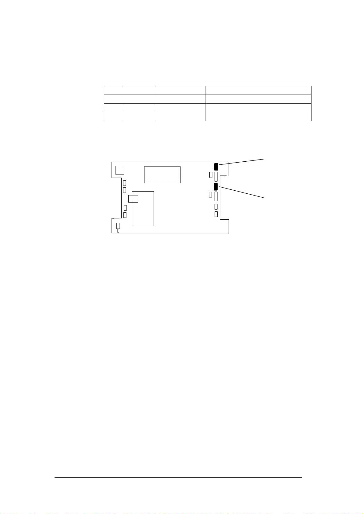
RS-485 Network Connectors (J6 and J7)
J6, J7
A Master HRX5000 is able to communicate with up to 15 Slave HRX5000s (or
HRX3000s) over a twisted pair RS-485 bus. 2 connectors are fitted in each
clock to make wiring easier in the field.
End to end cable length can be up to 1Km. The cable required is single
twisted pair with shield.
A suitable cable is Belden 9501 which is 24 awg (7X32) stranded, single
twisted pair with shield, PVC insulation. The RS Part Number 382-576 is for 1
box of 304 metres at £75.
J6 and J7 are connected pin to pin on the PCB. I.e. J6 pin 1 connects to J7
pin 1 etc. To connect 2 units together, wire pin 1 to pin 1 and pin 2 to pin 2.
Keep the screen pigtail as short as possible.
Pin Signal Direction
1 -ve In/Out
2+ve In/Out
3
4Screen
J6
J7
HRX5000 Technical Manual V1.2Page 6 of 18
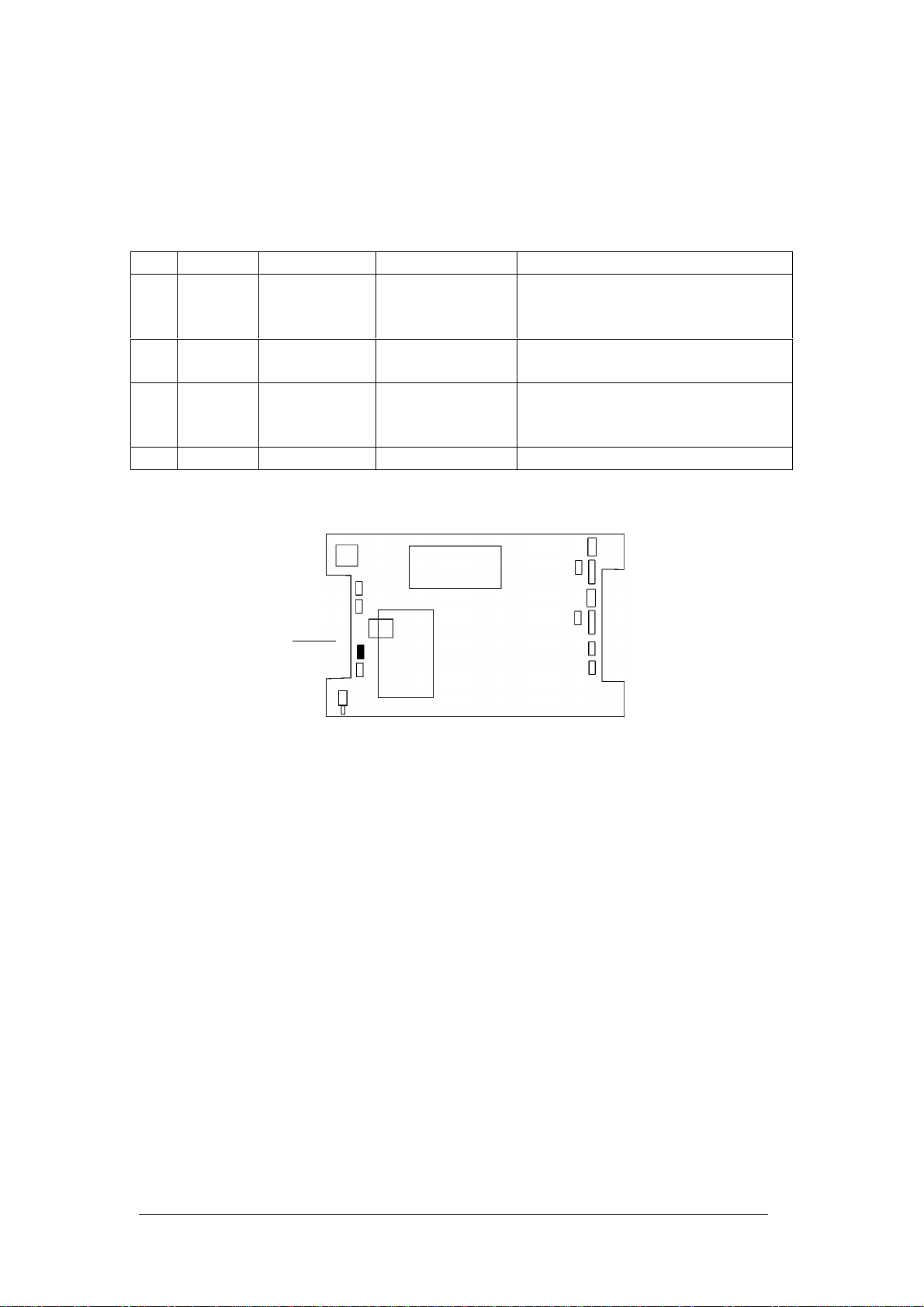
RS-232 to Printer (J19)
J19
The terminal uses an RS-232 output to a printer for the Fire Alarm evacuation
reports. The report is triggered by a contact closure on the Fire Alarm Input. It
can also be initiated from the PC.
The data format of the transmitted data to the printer is:
9600 baud, 8 Data bits, 1 Stop Bit, No Parity.
Using the Focus Software it is possible to command test printouts to be sent
from the Terminal to the printer. It is also possible to inspect the state of the
Printer's hardware handshake line. See menu option System | Fire Alarm.
Pin Signal Direction Printer DB-25 Notes
1Power Out 5-9 volts available to power an
external line driver. Current
limited to approx 50mA
2TXD Out RXD pin 3Transmit data. 9600 baud, 8
data, 1 stop, no parity
3RXD In RTS pin 20 Hardware handshake from
printer. Connect to Printer RTS
(Output) signal
4 0V 0V pin 7Signal Ground
J19
HRX5000 Technical Manual V1.2Page 7 of 18
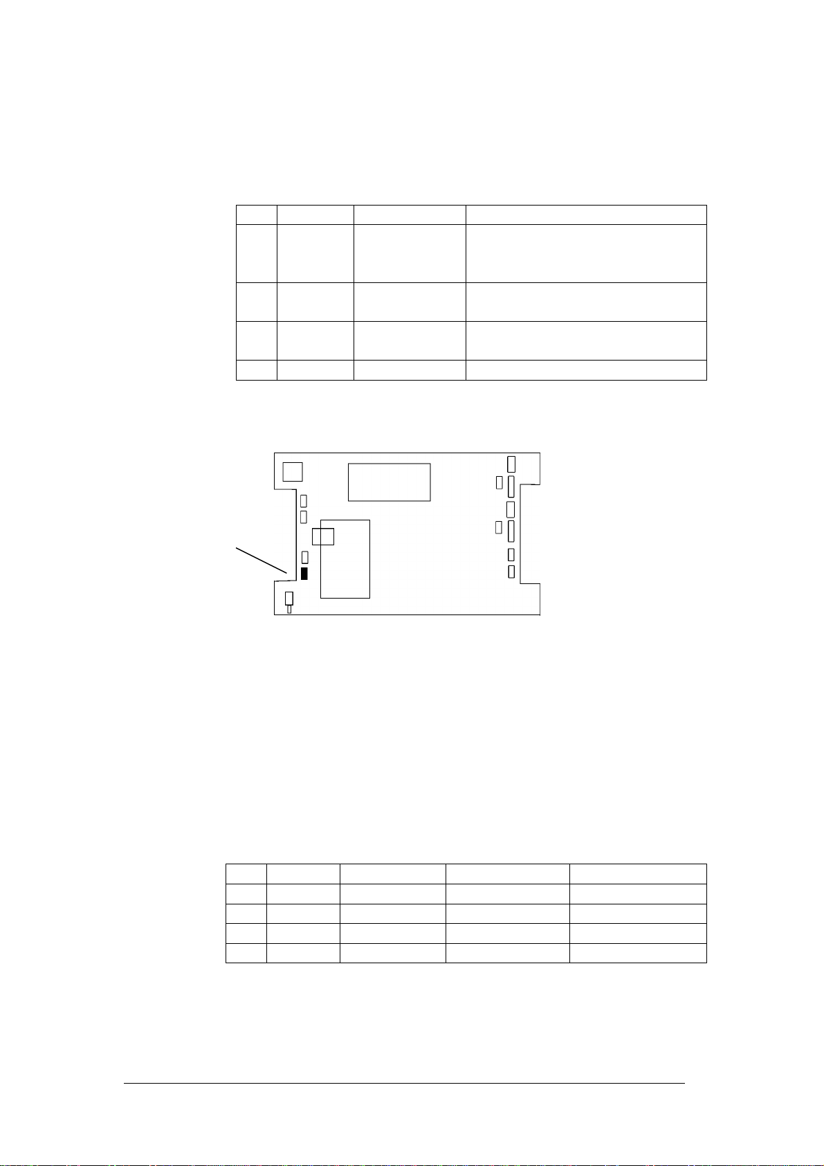
RS-232 to PC (J8)
J8
The terminal can communicate with the PC either by TCP/IP, RS-232 or
Modem. The connection method is set up in the Focus System | Clock
Utilities | Connection Setup screen. Here you specify a terminal name and a
connection method.
Connections:
Pin Signal Direction Notes
1Power Out 5-9 volts available to power an
external line driver. Current
limited to approx 50mA
2TXD Out Transmit data. 19,200 baud, 8
data, 1 stop, no parity
3RXD In Receive data. 19,200 baud, 8
data, 1 stop, no parity
4 0V Signal Ground
Pin Signal Direction PC 9 Way PC 25 Way
1Power Out
2TXD Out RXD (pin 2) RXD (pin 3)
3RXD In TXD (pin 3) TXD (pin 2)
4 0V 0V (pin 5) 0V (pin 7)
J8
HRX5000 Technical Manual V1.2Page 8 of 18
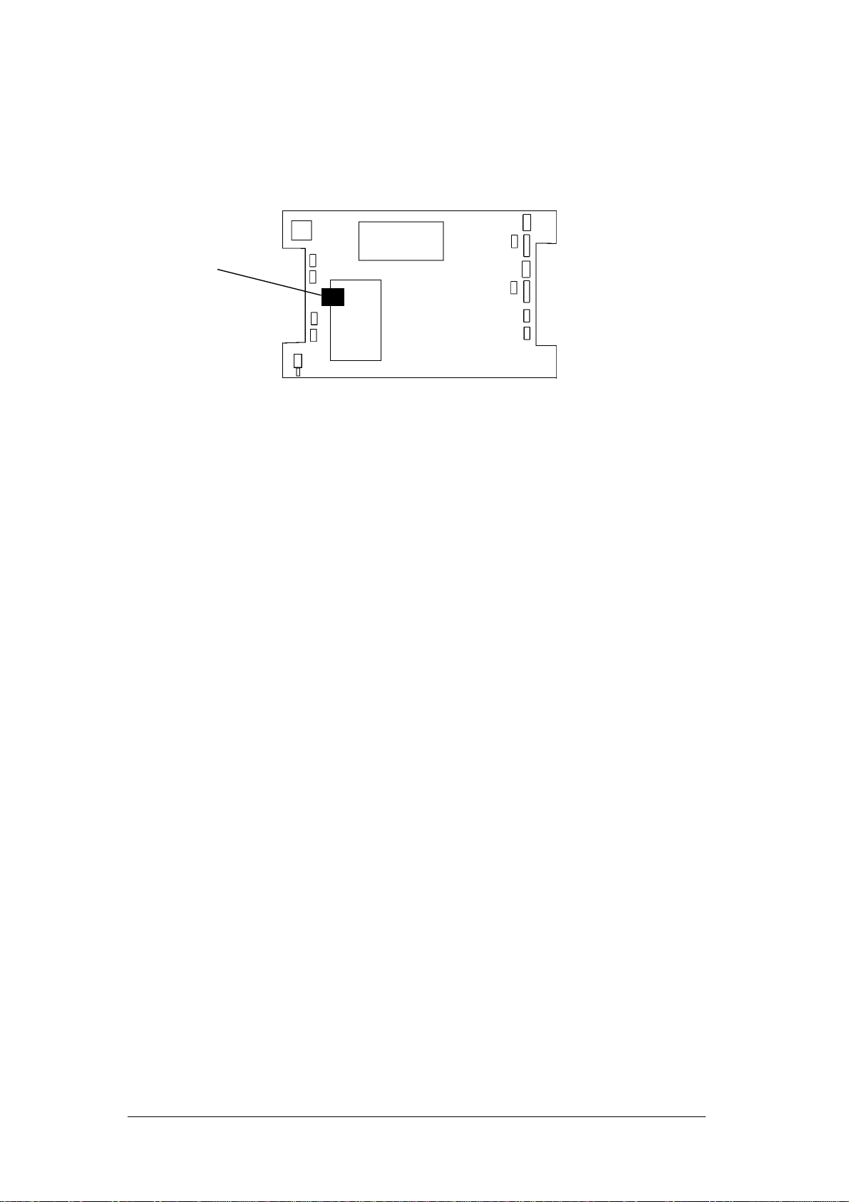
TCP/IP
The TCP/IP connection supports Ethernet 10/100 Base-T.
The IP address of the unit is set up via the Focus software using the System
| Clock Utilities | TCP/IP Tab. A password is required to modify the TCP/IP
address of the unit as inadvertent changes will cause loss of communication.
You would normally modify the IP Address by communicating over the RS232
cable from the PC.
TCP/IP

HRX5000 Technical Manual V1.2Page 9 of 18
Power (J21)
J21
The unit requires 9 to 12 volts DC at up to 500mA depending on configuration.
The unit is protected internally against reverse polarity connection.
Pin Signal Direction Notes
1 0V Signal Ground connected to
pin 2
2 0V
3+ve In 9-12 volts DC at up to 500mA
4+ve In Connected to Pin 3
J21

HRX5000 Technical Manual V1.2Page 10 of 18
Fire Alarm Input (J20)
J20
The Fire Alarm Input triggers the Fire Evacuation Report to be printed via the
RS-232 printer port. A voltage free pair of contacts triggers the report on
contact closure. The connections are doubled up on the connector with Pins 1
and 3 connected and Pins 2 and 4 connected. If desired, a push button switch
can be connected to one pair and the Fire Alarm panel connected to the other
pair. This will give a manual test or trigger input.
Pins 1 and 3 will normally show +5 volts with both inputs open circuit.
Pin Signal Direction Notes
1 FA In Fire Alarm Input
2 0V Signal Ground
3 FA In Connected internally to Pin 1
4 0V Connected internally to Pin 2
J20
HRX5000 Technical Manual V1.2Page 11 of 18
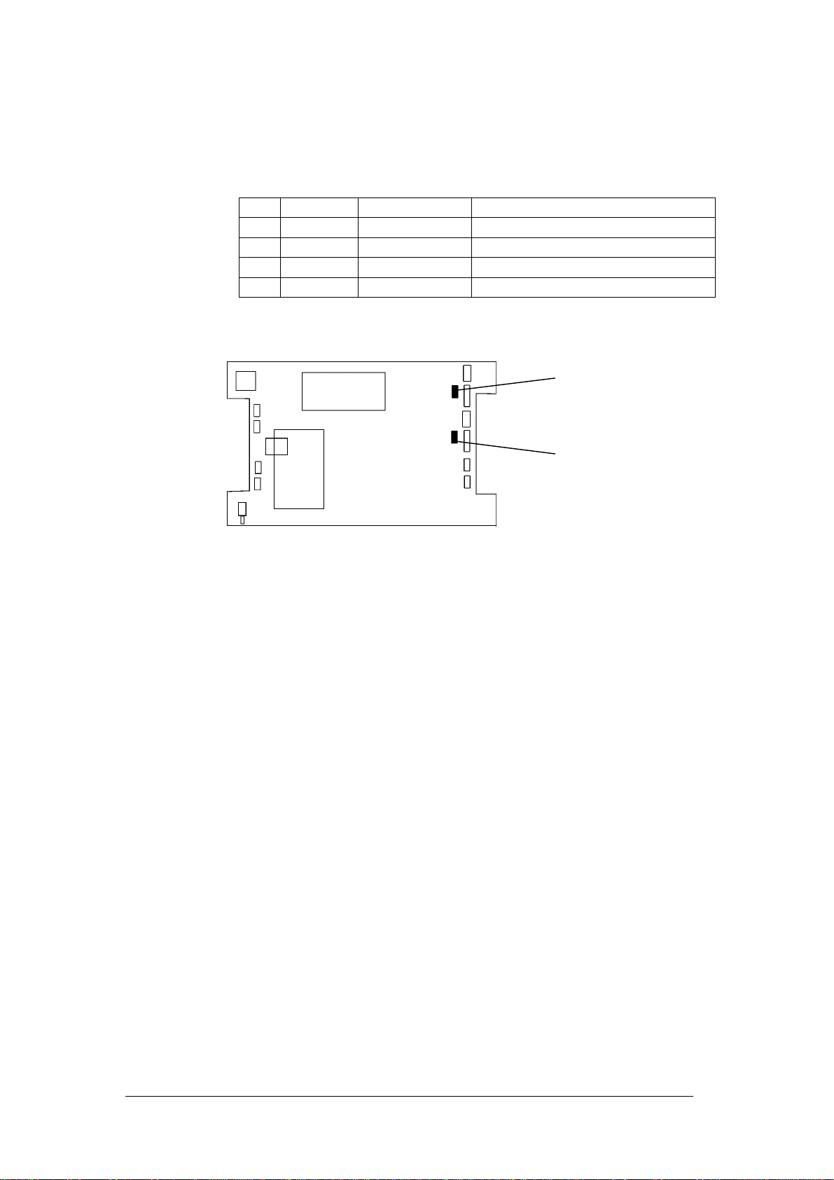
Relays (J12, J15)
J12, J15
The two relays each provide one set of changeover contacts for operating a
door release mechanism or a sounder.
The contacts are rated at up to 240 volts AC 100mA , or 12V DC 2 Amps. The
contacts are protected internally by transient suppressing Varistors.
Pin Signal Direction Notes
1 NC In/Out Normally Closed Contact
2 C In/Out Common Contact
3 NO In/Out Normally Open Contact
J12
J15

HRX5000 Technical Manual V1.2Page 12 of 18
Remote Readers (J13, J16)
J13, J16
NB: Pin 1 located at the TOP of the connector
Recommended cable for extending the reader distance:
Belden 9538 which is 8 core 24 awg (7X32) with overall screen.
RS Part number 382-475 is for 304 metres at £175.
Pin Signal Colour Direction Required
19 Volts Red In Yes
2Card Load Signal Violet In
3Signal Ground Black Yes
4Data Green In Yes
5Clock White In Yes
6Green LED Orange Out Yes
7Red LED Brown Out
8Sounder Yellow Out
J13
J16
HRX5000 Technical Manual V1.2Page 13 of 18
Remote Door Inputs (J14, J17)
J14, J17
Pin 1 and 2 connect to a normally closed door sensor such as a magnetic
reed contact. The contacts open when the door opens. With the contacts
open there is a 5 volt signal present on Pin 1.
Pin 3 and 4 connect to a Door Exit pushbutton. These contacts are normally
open when there will be a 5 volt signal on Pin 3. Egress timing is carried out
by the software in the terminal.
Pin Signal Direction Notes
1AJAR In Door Ajar
2 0V
3EXIT In Exit Pushbutton
4 0V
J14
J17
HRX5000 Technical Manual V1.2Page 14 of 18
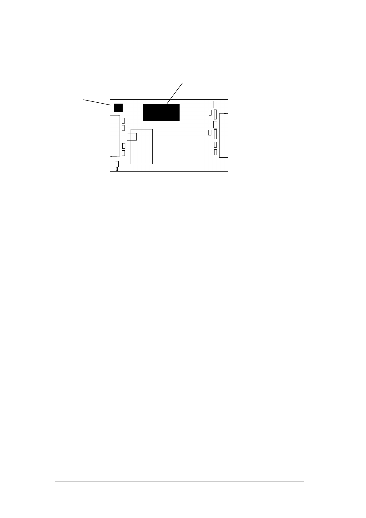
Modem (J3)
The unit can accept a plug in Modem which sits underneath the LCD. The
footprint is compatible with a PSTN landline modem or a GSM radio modem.
The PSTN Modem connects to the phone line via J3 which is a standard
modem line socket.
The GSM modem has a flying lead connecting to an aerial which , for best
results, should be mounted remotely from the clocking terminal itself.
Modem
J3

HRX5000 Technical Manual V1.2Page 15 of 18
Access Control
The HRX5000 supports Access Control for 2 Doors. Two independent groups
of connectors allow for connection to:
1. Proximity reader;
2. Door release device (latch or magnet) driven by a built in changeover
relay;
3. Door open sensor;
4. Door Exit button.
Each relay has an alternative use as a bell actuator.
1. Proximity Reader.
With the recommended minimum 5 wire connection the LED/Sounder
sequence is as follows:
LED Sounder Indicating
Idle Red Power ON
Card Presented Flashes GREEN Beeps Card read
If Access Granted Relights GREEN
for the duration the
Door is released
Access Grant
If Access Denied Remains RED Access Deny
2. Door Release.
The contacts are rated at up to 240 volts AC 100mA , or 12V DC 2 Amps. The
contacts are protected internally by transient suppressing Varistors.
3. Door Open sensor.
Connects to a set of contacts that are closed when the door is closed (such as
a magnetic reed switch). These contacts are monitored and can initiate a
Door Forced Alarm and a Door Ajar Alarm.
4. Door Exit switch.
Connect a Normally Open push button to this input to release the door for a
predetermined interval. When the contacts close (button pressed) the door
relay will operate (door released). When the contacts open (button released)
the Door Release timer starts. This can be set from the Focus software
Access Control | Doors screen. At the end of the timeout period the relay will
de-energise, locking the door.

HRX5000 Technical Manual V1.2Page 16 of 18
Master/Slave systems
In a Master/Slave configuration, the master holds all the Door Rules and the
Access Rules as well as the Access Clocking Records. The Access Clocking
records are downloaded at the same time as the Time and Attendance
Records.
The Master holds:
20 Door Rules
100 Access Rules
100 Access Groups
10,000 Time & Attendance and Access clockings
Fire Alarm Interaction
Each door can be individually programmed to unlock on Fire Alarm activation.
This is carried out by setting the Fire Alarm Release timer in the Door
Definition within Focus Clock Utilities.
Bells
The HRX5000 holds up to 20 Bell time records that can be shared between
the 2 relays. Each record specifies:
The relay 1 or 2
The activation time in hours and minutes (no seconds)
The duration in seconds (up to 60 seconds)
The days of the week on which the rule applies.
Fire Alarm Printer
The terminal uses RS-232 to send data to the fire alarm printer. This enables
a dedicated cable to be used (rather than using the network infrastructure)
and distances of around 50 metres can be achieved.
The printer must be capable of printing 'Raw Text'. Many printers only work
when driven by an application using Windows or similar printer drivers. Before
sourcing a printer ensure it can print raw text and has either an RS-232
interface (preferable) or a 'parallel Centronics' interface (also referred to as
IEEE 1284 Bi-directional parallel).

HRX5000 Technical Manual V1.2Page 17 of 18
Recommended Printer:
OKI B4250 Mono Laser plus optional serial RS-232 interface. Source
www.printerland.co.uk.
If the printer does not have a serial interface it is possible, though less
convenient, to use an external Serial-to-Parallel converter. This must be
capable of converting serial data in the format 9600 Baud, 8 data bits , 1 Stop
bit to Parallel data.
One such converter is the 'Autostop' or SPC-10 converter. This requires an
external power supply delivering 9 to 12 volts AC or DC. If DC is used the
polarity on the connector must be observed, which is NEGATIVE TO THE
TIP. Wire the 25 way connector in accordance with the table for J19. In
normal operation, all the DIP switches on the converter should be OFF, giving
the correct baud rate and word format for the terminal.
Note that it is not possible to interface to a printer USB port.

HRX5000 Technical Manual V1.2Page 18 of 18
Issue History
Issue Date Firmware Focus Changes
V1.0 July 2006 Original Issue
V1.1 11/9/2006 2.002 2.07 Access Control and Bells
Descriptions Added
V1.2 29/9/2006 Fire Alarm printer details added.
Table of contents


