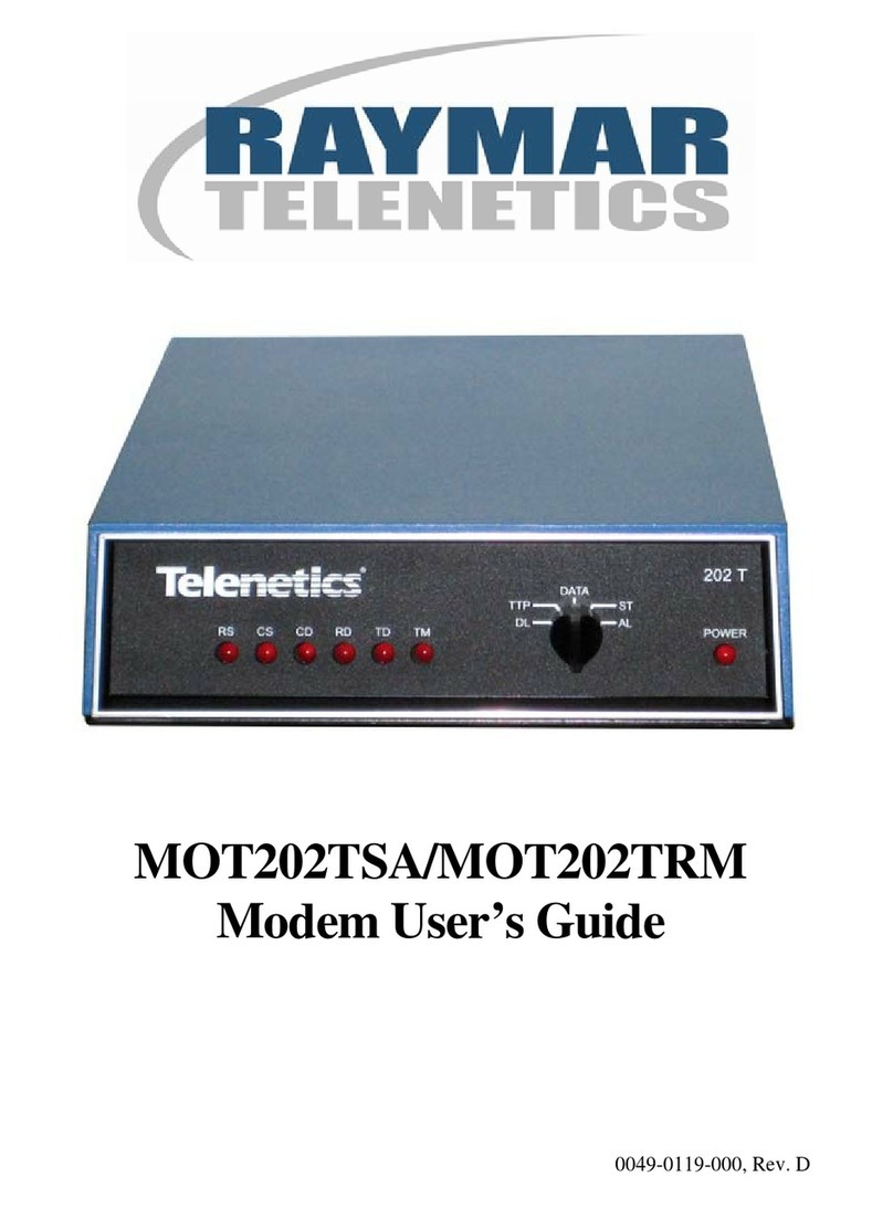
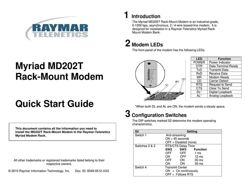
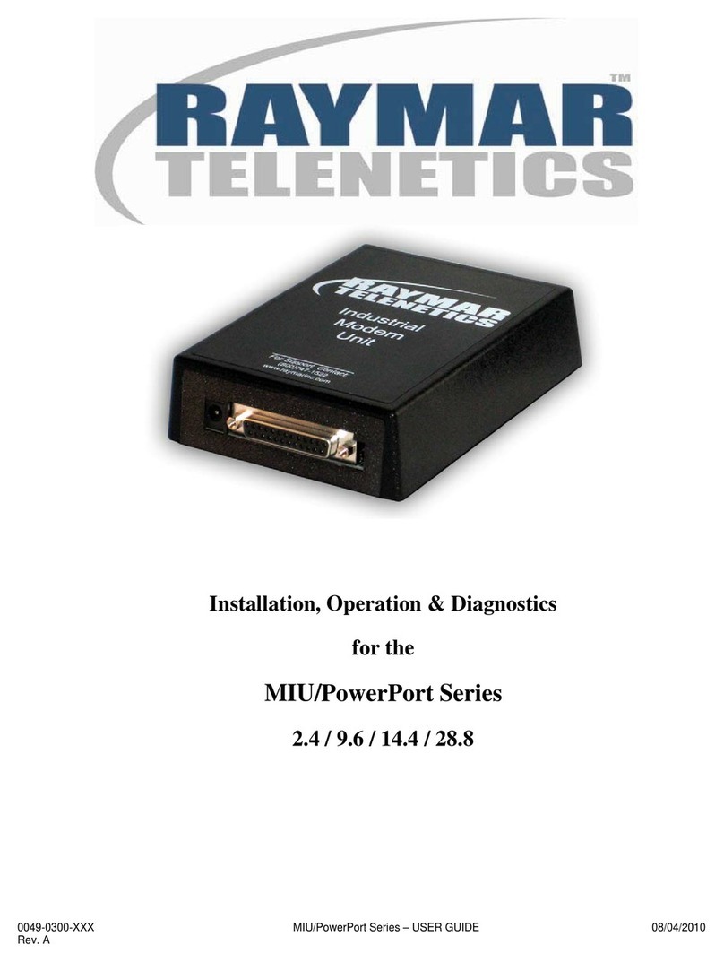
Raymar Alliance V.34M User manual

0049-2702-XXX Alliance Series Modems – USER MANUAL 08/05/2010
Rev. A
Alliance Series Modems
Instruction Manual
Alliance V.34M
Alliance V.34
Alliance V.32/19.2M
Alliance V.32/19.2
Alliance V.32/14.4M
Alliance V.32/14.4
Alliance V.32M
Alliance V.32

0049-2702-XXX Alliance Series Modems – USER MANUAL 08/05/2010
Rev. A Page i
Raymar Information Technology, Inc.
7325 Roseville Road
Sacramento, CA 95842
800-695-1951
Fax: 916-783-1952

0049-2702-XXX Alliance Series Modems – USER MANUAL 08/05/2010
Rev. A Page ii
About the Alliance Series Modems:
The Alliance Series modems are easy to use and can operate in a variety of applications.
Your modem is initially configured to operate in Hayes emulation mode, but can be easily
reconfigured for other applications, as explained in Chapter 1.
Before operating the modem, it is advised that the applicable notices in Appendix F of this
manual be read. Appendix F includes pertinent Government regulatory information and
Government recommendations concerning operation of the modem.
About this Manual:
The products and programs described in this User’s Guide are licensed products
of Raymar-Telenetics. This User’s Guide contains proprietary information
protected by copyright, and this User’s Guide and all accompanying hardware
and documentation are copyrighted.
Raymar-Telenetics does not warrant that the hardware will work properly in all
environments and applications, and makes no warranty and representation,
either implied or expressed, with respect to the quality, performance,
merchantability, or fitness for a particular purpose.
Information in this User’s Guide is subject to change without notice and does not
represent a commitment on the part of Raymar-Telenetics. Raymar-Telenetics
assumes no responsibility for any inaccuracies that may be contained in this
User’s Guide.
Raymar-Telenetics makes no commitment to update or keep current the
information in this User’s Guide, and reserves the right to make changes to this
User’s Guide and/or product without notice.
No part of this manual may be reproduced or transmitted in any form or by any
means, electronic or mechanical, including photocopying, recording, or
information storage and retrieval systems, for any purpose other than the
purchaser's personal use, without the express written permission of Raymar-
Telenetics.
©Copyright 2010 Raymar Information Technology, Inc.
7325 Roseville Road
Sacramento, California 95842
Tel: 800-695-1951 Direct: +1-916-783-1951
Fax: 916-783-1952
Web site: www.raymarinc.com
0049-2702-XXX Alliance Series Modems – USER MANUAL 08/05/2010
Rev. A Page iii
TABLE of CONTENTS
1. GETTING STARTED..........................................Page 1
2. OPTIONS: CUSTOMIZING THE MODEM
SETUP........................................................Page 21
3. GENERAL OPERATION & SPECIAL
FEATURES................................................Page 69
4. HAYES EMULATION MODE...........................Page 108
5. V.25bis AUTODIALER.......................................Page 135
6. DIAGNOSTICS...................................................Page 141
7. APPENDIX A – TECHNICAL DATA ..............Page 157
8. APPENDIX B – QUICK SETUP
CONFIGURATION..........................................Page 162
9. APPENDIX C – QUICK-CHANGE
CONFIGURATION SCREENS........................Page 173
10.APPENDIX D – CONNECTORS,
ADAPTERS and JUMPERS..............................Page 184
11.APPENDIX E – LOW-PROFILE
RACK-MOUNT MODEM................................Page 190
12.APPENDIX F – REGULATORY NOTICES.....Page 193
13.LIMITED WARRANTY ………………………Page 196
14.RMA PROCEDURE ………………………….. Page 197

0049-2702-XXX Alliance Series Modems – USER MANUAL 08/05/2010
Rev. A Page 1 of 197
CHAPTER ONE – GETTING STARTED
This instruction manual applies to the following Alliance Series modems:
•Alliance V.34M (ALX V.34M)
•Alliance V.34 (ALX V.34)
•Alliance V.32/19.2M (ALX V.32/19.2M)
•Alliance V.32/19.2 (ALX V.32/19.2)
•Alliance V.32/14.4M (ALX V.32/14.4M)
•Alliance V.32/14.4 (ALX V.32/14.4)
•Alliance V.32M (ALX V.32M)
•Alliance V.32 (ALX V.32)
The primary difference between the Alliance (ALX) models is the maximum speed (data rate), as
indicated above. Another significant difference is that the ALX V.34 and V.34M comply with
ITU-T Recommendation V.34, while all other models comply with ITU-T V.32/V.32bis. “M,” as
in “ALX V.34M,” indicates that the modem is network manageable (it can be managed using
Raymar-Telenetics’ network management software). Other differences are explained later in this
manual.
For simplicity, all models are referred to in this manual as the “ALX modem” or “the ALX.”
However, if a specific feature, option, etc., applies only to a specific model or models, this is
clearly stated. Otherwise, all instructions and other information apply to all Alliance Series
modems listed above.
All information applies to both the stand-alone and full-size rack-mount versions of the above-
listed modems. Specialized low-profile rack-mount versions, designed for use in high-density rack
enclosures, are described in Appendix E.
Quick Setups for a Quick Start
The simplest way to setup the ALX modem for immediate use is to
select one of the factory-preset Quick Setup configurations. Quick
Setups are explained beginning on page 8.

0049-2702-XXX Alliance Series Modems – USER MANUAL 08/05/2010
Rev. A Page 2 of 197
INSTALLATION
Unpacking
Keep the original shipping carton in case it is necessary to return the modem for any reason.
Failure to comply may result in voiding the warranty.
In addition to the ALX modem, the shipping carton should contain:
•A power transformer (with cable attached)
•A two-conductor crossover cable (for a dial line connection)
•A four-conductor cable (for a leased line connection)
If the modem will be operated in a manual dial mode, you will also need a standard telephone set.
Cables
To connect the modem to a dial line, use the provided two-conductor cable. To connect the modem
to a leased line, use the provided four-conductor cable. To set up the ALX for Leased Line Auto-
Recovery, use both cables to connect the leased line and a (backup) dial line. To connect the
modem to the DTE (data terminal equipment, usually a computer), use a TIA/EIA RS-232
interface cable (not supplied).
Connections
Figure 1-1 shows how the modem is connected to the computer or terminal, power, phone lines and
handset (optional). Do not install the modem more than 50 feet from the DTE. DTE speeds
greater than 19.2 Kbps require a much shorter low-capacitance DTE interface cable.
For all applications:
•Use a TIA/EIA RS-232 interface cable (not supplied) to connect the modem connector
marked “DTE” to the computer or other DTE.
•Attach the power transformer cable to the modem receptacle marked “POWER,” and
plug the other end into a 117 VAC power outlet.
For dialup applications:
•Use the supplied two-conductor crossover cable to connect the modem connector labeled
“TX DIAL” to the dial telephone line modular wall jack. Do not bundle the phone cable
and TIA/EIA interface cables together.
•Optional: If you want to use the telephone line for voice transmissions (when the ALX is
not operating in data mode) or for manual dial operation, plug a standard telephone set
into the jack in the rear of the modem labeled “PHONE.”

0049-2702-XXX Alliance Series Modems – USER MANUAL 08/05/2010
Rev. A Page 3 of 197
For leased line applications:
•Use the supplied four-conductor cable to connect the modem connector labeled
“LEASED LINE” into the leased line modular wall jack (type USOC JM8). Do not
bundle the leased line and TIA/EIA interface cables together.
If your application requires an 8-pin connector, use the alternate leased line connector
shown in Figure 1-1 instead of the 6-pin “LEASED LINE” connector. To use the
alternate connector, you will need to provide your own cable. (See Appendix A for pin-
out information.)
The same cable is used whether the leased line is a 4-wire or 2-wire line. In a 4-wire
application, the green and red wires are the TRANSMIT pair, and the yellow and black
wires are the RECEIVE pair. For a 2-wire line, only the green and red wires are used.
Figure 1-1. Installation of the ALX modem

0049-2702-XXX Alliance Series Modems – USER MANUAL 08/05/2010
Rev. A Page 4 of 197
Jumpers
For most applications, do not change the internal jumper switches. However, jumper switches must
be changed if you need to connect frame ground to signal ground, switch from A/A1 control to
MI/MIC control, change the function of TIA/EIA pin 25 (test mode indicator, by default) or use the
ALX in a DC rack enclosure. For detailed jumper information, see Appendix D.
FRONT PANEL LCD and CONTROLS
This section explains how to use the liquid crystal display (LCD) and pushbuttons on the modem’s
front panel (Figure 1-2). You will need to use the LCD and pushbuttons to select a Quick Setup
configuration, as explained in the next section.
Figure 1-2. Pushbuttons and LCD on the modem’s front panel
How to Use the Pushbuttons
By using the front panel pushbuttons, you can make selections as indicated on the LCD to
choose option settings, initiate tests and perform other operations. (In Hayes mode, many of
these features can be accessed via the front panel or by using AT commands.) The possible
choices for each option are shown on the LCD and on the LCD flow chart in the back of this
manual.

0049-2702-XXX Alliance Series Modems – USER MANUAL 08/05/2010
Rev. A Page 5 of 197
Arrow Pushbuttons
The left arrow ( ) and right arrow ( ) pushbuttons are used to display additional or
previous screens that are part of the same menu. See Figure 1-3.
If a menu has more than one screen, each screen is numbered in the upper right corner, as
follows: <2>. (See the screen represented below.) If a menu has no screen number, it has only
one screen. Additional menu screens, where present, show additional option selections.
Numbered Pushbuttons
Pushbuttons 1, 2 and 3 correspond to segments 1, 2 and 3 of the LCD screen. These segments
(left, middle and right positions of the LCD screen) are numbered on the modem’s front panel.
To make a selection from a menu screen, push the button with the same number as the selection
you want.
With respect to how the LCD flow chart is organized, pushbuttons 1, 2 and 3 take you to a lower
level – or, where there is no route to a lower level, select an option setting.
Figure 1-3. Summary of pushbutton control functions.

0049-2702-XXX Alliance Series Modems – USER MANUAL 08/05/2010
Rev. A Page 6 of 197
ENT Pushbutton
To exit from a displayed screen, press the ENT (enter) pushbutton. With respect to how the
LCD flow chart is organized, pushing the ENT button moves you upward through the chart
(toward the MAIN MENU).
If you become lost, press the ENT button repeatedly to return to screen 1 of the MAIN MENU.
Pressing ENT repeatedly after you have arrived at MAIN MENU screen 1 causes the LCD to
alternate between the TIA/EIA status screen and the MAIN MENU. (In the case of most tests,
the ENT button cannot be used to exit the test screen once the test has been activated; you must
first press the ENT button and then select OFF to end the test.)
Note: If you have selected a Quick Setup or have changed certain option settings, pressing the
ENT button as you exit the SETUP menu causes the modem to rest.
DEC/INC (Decrease/Increase) Screens
Many option screens show the abbreviations DEC and INC on the bottom line of the LCD
display, with option settings shown on the top line (usually to the right). On most DEC/INC
screens, you can cycle through the available option settings by pressing pushbutton 1 (DEC) or
pushbutton 3 (INC). (DEC decreases numerical values, INC increases them.) When you see the
setting you want, press pushbutton 2 to select it. The setting will flash, indicating that it is
selected.
A few of the DEC/INC screens are used to enter or change a text or number string one digit or
one character at a time (for example, the PHONE CELL, ADDRESS and PASSWORD screens).
Special instructions for these screens are included later in this manual.
Power-On Screen
When the ALX modem is powered on, the LCD momentarily displays the power-on screen,
which typically looks like this:
The top line identifies the modem type and model. The bottom line shows the revision level of
the software used in the ALX modem. If you need to call Raymar-Telenetics’ Technical Support
Group with a question or service problem, please be prepared to provide the software revision
level of your unit.
After showing the power-on screen for about 2 seconds, the ALX displays the TIA/EIA status
screen.

0049-2702-XXX Alliance Series Modems – USER MANUAL 08/05/2010
Rev. A Page 7 of 197
TIA/EIA Status Screen
The TIA/EIA status screen, shown below, indicates the operational status of the ALX as well as
the condition of certain TIA/EIA RS-232 leads. The abbreviations that may appear are identified
below; however, typically, only a few of these abbreviations will be displayed during actual
operation.
Status screen abbreviations:
D Dial line occupied
R Ringing (R appears in same position as D)
S Connection secured by security handshake (S appears in same position as D.
S and D may flash alternately.)
TR Data Terminal Ready
MR Data Set Ready
RS Request to Send
CS Clear to Send
TD Transmit Data
28.8, 19.2, 14.4, 9600, 4800, etc. Transmitter (TX) data rate, or link rate in Kbps
(thousand bits per second) or bps (bits per second). Speed of data transmission on
the line.
TM Test mode
ER Error (poor signal quality)
CD Carrier Detect
RD Receive Data
Codes beginning with “H” (such as H-01) in the lower left corner of the status screen indicate
that the ALX is handshaking with another modem (attempting to establish a connection). When
the modem is off-line, the work “idle” is displayed in the same position.
(Additional status screens are described in Chapter 6.)

0049-2702-XXX Alliance Series Modems – USER MANUAL 08/05/2010
Rev. A Page 8 of 197
QUICK SETUP
To quickly set up the ALX modem for immediate use (or to quickly change the modem’s
configuration for an alternate mode of operation), select one of the factory-preset Quick Setup
configurations (Table 1-1).
When a Quick Setup is selected, the ALX automatically sets all of its options to the settings that best
suit the application type (Quick Setup) you have selected. Selecting a Quick Setup overwrites
previously stored option settings but does not affect telephone numbers which may be stored in the
modem’s memory.
You may later customize a Quick Setup configuration by changing specific option settings (Chapter
2).
How to Select a Quick Setup
To select (activate) a Quick Setup configuration, follow the steps below. While doing so, it may be
helpful to refer to the LCD flow chart in the back of this manual.
1. Press the ENT (enter) pushbutton on the modem’s front panel.
Screen 1 of the MAIN MENU will be displayed:
You may have to press the ENT button two or more times to see screen 1 of the MAIN MENU.
This will depend on which screen is displayed initially.
2. Press pushbutton 2.
Screen 1 of the QUICK SETUP menu will be displayed:
3. Move to the QUICK SETUP screen that shows the configuration you want.
Use the right arrow button to move from QUICK SETUP screen 1 to the QUICK SETUP screen
for the configuration you want. You may also use the left arrow button to move “backward”
through the QUICK SETUP menu.
** There is a QUICK SETUP screen for each Quick Setup configuration. For a brief description
of each Quick Setup configuration, see Table 1-1.

0049-2702-XXX Alliance Series Modems – USER MANUAL 08/05/2010
Rev. A Page 9 of 197
4. When the LCD shows the Quick Setup configuration you want, press pushbutton 2.
This will cause the bottom line of the display to flash on and off.
5. Press the ENT button twice.
As you do this, you will see SETUP screen 1; then - after you press the ENT button a second
time – the modem will reset. (It is at this point that the selected Quick Setup actually takes
effect.)
The modem is now set up for the Quick Setup configuration you have selected. All options will
be set as shown in Appendix B. If you want to customize the Quick Setup configuration by
changing individual options, see Chapter 2. For Hayes mode options, see Chapter 4.

0049-2702-XXX Alliance Series Modems – USER MANUAL 08/05/2010
Rev. A Page 10 of 197
Table 1-1. ALX Quick Setup Configurations
Quick Setup as
Identified on LCD
Description
2-WIRE DIAL HAYES EMULATION MODE –
This Quick Setup (for communication over ordinary phone lines)
allows the ALX modem to automatically dial (autodial) a previously
stored phone number and respond to Hayes commands. This mode
is compatible with communication software packages that use
Hayes-style “AT” commands. The Hayes mode Quick Setup is the
factory default configuration for the ALX modem.
2-WIRE DIAL V.25bis MODE, ASYNCHRONOUS –
In V.25bis mode, the ALX operates in conformance with ITU-T1
Recommendation V.25bis, allowing you to store and direct dial or
autodial phone numbers from the DTE. Use Quick Setup 2 if the
DTE connected to the modem is asynchronous.
2-WIRE DIAL V.25bis MODE, SYNCHRONOUS
CHARACTER ORIENTED –
Same as Quick Setup 2 except for data protocol. Use Quick Setup 3
if the DTE is synchronous character oriented (bisynchronous).
2-WIRE DIAL V.25bis MODE, SYNCHRONOUS BIT
ORIENTED –
Same as Quick Setup 2 except for data protocol. Use Quick Setup 4
if the DTE is synchronous bit oriented (SDLC/HDLC).
2-WIRE DIAL DUMB MODE –
When the ALX is in Dumb mode, you can use the modem for dial
answer-only applications, dial a previously stored telephone number
from the front panel, or dial phone numbers via an external source
(telephone).
2-WIRE LEASED LINE ORIGINATE MODE –
In Leased Line mode, the ALX connects to the leased line and
stands ready to send and receive data. Use Quick Setup 6 if the
leased line is a 2-wire line and you want to configure the ALX as the
originate modem.
2-WIRE LEASED LINE ANSWER MODE –
Same as Quick Setup 6 except for modem answer/originate status.
Use Quick Setup 7 if the leased line is a 2-wire line and you want to
configure the ALX as the answer modem.
1International Telecommunications Union – Telecommunications Sector, formerly CCITT.

0049-2702-XXX Alliance Series Modems – USER MANUAL 08/05/2010
Rev. A Page 11 of 197
4-WIRE LEASED LINE ORIGINATE MODE –
Same as Quick Setup 6 except for line type. Use Quick Setup 8 if
the leased line is a 4-wire line and you want to configure the ALX as
the originate modem.
4-WIRE LEASED LINE ANSWER MODE –
Same as Quick Setup 6 except for line type and answer/originate
status. Use Quick Setup 9 if the leased line is a 4-wire line and you
want to configure the ALX as the answer modem.
Quick Setups 10 – 16:
Some ALX models do not support all Quick Setup modes. (All support Quick Setups 01-09.)
If your model does not support a particular Quick Setup mode, you will not be able to access
the Quick Setup screen for that mode. For details, see Table 1-2.
V.33 LEASED LINE OPERATION –
This Quick Setup configures the ALX for V.33 operation.
2-WIRE DIAL BELL 208 OPERATION –
This Quick Setup configures the ALX for 2-wire dial operation
compatible with Bell standard 208B.
2-WIRE DIAL V.3x/208 AUTO-DETECT MODE –
This Quick Setup configures the ALX to automatically select V.34,
V.32bis (V.13) or Bell 208 operation, depending on the mode of the
originating modem.
4-WIRE LEASED LINE V.29 MODE –
This Quick Setup configures the ALX for V.29 operation, for
compatibility with V.29 modems.
V.29 FAST MASTER MODE –
This Quick Setup configures the ALX for V.29 fast train master
operation, for use in a multidrop network where multiple remote
ALX (slave) modems share the master ALX as the host modem.
V.29 FAST SLAVE MODE –
This Quick Setup configures the ALX for V.29 fast train slave
operation, for use in a multidrop network where multiple remote
ALX (slave) modems share the same ALX hose (master) modem.
2-WIRE DIAL V.27 MODE-
This Quick Setup configures the ALX for 2-wire dial operation in
compliance with ITU-T V.27ter.

0049-2702-XXX Alliance Series Modems – USER MANUAL 08/05/2010
Rev. A Page 12 of 197
Table 1-2. Quick Setup Modes
Supported by Specific ALX Models
ALX Models
Quick Setup Mode V.32,
V.32M V.32/14.4, V.32/14.4M,
V.32/19.2, V.32/19.2M,
V.34, V.34M
Hayes (01)
V.25bis (02–04)
Dumb (05)
Leased (06-09)
Y Y
V.33 (10) N Y
Bell 208 (11-12) N Y
V.29 (13-15) N Opt.
V.27 (16) N Opt.
Y- Yes; supported. N - No; not supported.
Opt. - Optional; available only on certain versions of the listed model.
V.26: Models with V.29/V.27 option also support V.26 operation. (However,
there is no V.26 Quick Setup.)

0049-2702-XXX Alliance Series Modems – USER MANUAL 08/05/2010
Rev. A Page 13 of 197
BASIC OPERATION
To assist you in getting the ALX modem up and running, the following sections provide basic
information for each of the modem’s primary operating modes. For additional operating
information, refer to the remaining chapters in this manual. If you encounter difficulty, refer to the
section titled If You Have Problems at the end of this chapter.
2-Wire Dial Hayes Mode
Two-wire dial Hayes emulation mode is the factory default configuration for the ALX modem.
Hayes mode operation is explained in detail in Chapter 4.
To dial a telephone number in Hayes mode, type the Hayes command AT D on your computer or
terminal keyboard followed by the number you want to call, for example:
AT D 5551212 [CR]
Dashes or spaces may be included for clarity, but they are not necessary. (The ALX will ignore
them.) A carriage return [CR] or period is required at the end of each command line. (On most
keyboards, the carriage return [CR] key is labeled “Enter” or “Return.”) In response to the
command line shown above, the ALX will dial the number 555-1212.
To dial an access code such as 9 to dial out of your building, insert the access code and a comma in
the dial string:
AT D 9,5551212 [CR]
The comma causes the ALX to pause for 2 seconds after the access code before dialing the number.
When a phone number is successfully dialed, a “CONNECT” message appears on the computer
screen, and the LCD on the ALX displays a status screen that typically looks like this:
TD and RD will flash (to indicate that the modem is transmitting and receiving data).
To terminate a call, first enter the escape sequence +++. When the OK response appears on the DTE
screen, enter the command AT H. An alternate method is to drop the DTR signal from the DTE. If
you are using a computer with a communication software program, follow the program’s
instructions for initiating and terminating calls.

0049-2702-XXX Alliance Series Modems – USER MANUAL 08/05/2010
Rev. A Page 14 of 197
2-Wire Dial V.25bis Mode
The ALX modem supports three types of V.25bis operation – asynchronous, synchronous character
oriented or synchronous bit oriented. There is a Quick Setup for each V.25bis type, as shown in
Table 1-1. For V.25bis operation, the modem must be configured to use the same data protocol
(asynchronous, synchronous character oriented or synchronous bit oriented) – as the attached DTE.
If you have selected the correct V.25bis Quick Setup, the data protocol will be set automatically to
the correct setting. V.25bis mode operation and commands are explained in detail in Chapter 5.
Asynchronous V.25bis Operation
For asynchronous V.25bis operation, the data format of the DTE should be set to 7 data bits with
even parity and one stop bit. (Note that the default DTE interface rate is 38.4 Kbps in
asynchronous mode.)
In asynchronous applications, V.25bis commands (listed in Chapter 5) may be entered from the DTE
keyboard. For example, the simplest command sequence is CRN 3331234. In response to this
command, the ALX sends a VAL result code (indicating that the command has been accepted), dials
the telephone number, 333-1234, and then waits for an answer tone from a distant modem. If no
carrier is detected within a given time (45 seconds by default), the modem automatically releases the
line and sends a CFI NT result code.
When a call is successfully connected, the TIA/EIA status screen on the ALX will typically look like
this:
Synchronous V.25bis Operation
For synchronous V.25bis operation, set the data format of the DTE to 7 data bits with odd parity.
In synchronous applications, the V.25bis commands can facilitate computer-controlled operations.
Synchronous bit-oriented operation uses High Level Data Link Control (HDLC) formatting. In
synchronous character-oriented operation, messages are framed by synchronous start-of-text and
end-of-text characters, with the start-of-text character preceded by two synchronous (SY) characters.
2-Wire Dial Dumb Mode
Dumb mode is used primarily for manual call origination, answer-only applications and in
conjunction with certain dial back security systems that utilize MI/MIC signals to place the modem
on-line. (If you need to configure the modem for MI/MIC use, refer to Appendix D).
After the Quick Setup for 2-wire dial Dumb mode has been selected, the ALX is configured to
automatically answer incoming calls. The only other requirement is that the DTE must provide the
DTR signal (TR on the TIA/EIA status screen) to the modem or DTR must be set to TRUE (using
the modem’s DTR from EIA option screen).

0049-2702-XXX Alliance Series Modems – USER MANUAL 08/05/2010
Rev. A Page 15 of 197
For additional information on dumb mode, see Chapter 3 (Front Panel Autodialing and Dumb Mode
and Bell 208 Operation sections).
Leased Line (2- or 4-Wire) Mode
This section does not apply to V.33 and V.29 leased line operation; these modes are covered in
subsequent sections.
The following information applies to both 2-wire and 4-wire leased line operation:
•The modem must be configured for the correct line type –
2-wire or 4-wire. If you have selected the correct Leased Line Quick Setup, the line type
will be set automatically to the correct setting.
•One modem must be set to originate mode and the other to answer mode.
If you have selected the correct Leased Line Quick Setup, the answer/originate status will
be set automatically to the correct setting.
•By default, V.34 leased line operation is restricted to data rates of 2400 bps or higher.
V.32 operation leased line operation is restricted to data rates of 4800 bps or higher.
•Lines can be conditioned or unconditioned.
•Leased line modes default to synchronous data type, but may be changed to
asynchronous. (If the data type is asynchronous, error correction may be used.)
After you select the appropriate Leased Line Quick Setup, the answer and originate modems will
“handshake” and then connect. When the connection is established, the TIA/EIA status screen will
be present. Typically this screen will look like this:
V.33 Leased Line Operation
All ALX models, except the ALX V.32 and ALX V.32M, support V.33 operation. All features,
options and other information in this manual identified as V.33 mode-related apply only to models
equipped for V.33 operation. If you are not sure if your modem supports V.33 operation, check the
Quick Setup menu on the front panel LCD. Quick Setup 10 is present only on models that support
V.33 operation.
V.33 operation is synchronous only and is restricted to speeds of 12.0 and 14.4 Kbps.
A 4-wire line must be used (conditioned or unconditioned), and both connected modems must
be set for V.33 operation.

0049-2702-XXX Alliance Series Modems – USER MANUAL 08/05/2010
Rev. A Page 16 of 197
After the V.33 Leased Line Quick Setup has been selected, the ALX immediately begins the training
sequence and is ready to communicate with the other modem. The second modem to come online
automatically establishes the data link; this may be either the local or remote unit.
When the local modem has established a connection with the remote unit, the TIA/EIA status screen
will be present. Typically this screen will look like this:
2-Wire Dial Bell 208 Operation
All ALX models, except the ALX V.32 and ALX V.32M, support Bell 208 operation. All features,
options and other information in this manual identified as Bell 208 mode-related apply only to
models equipped for Bell 208 operation. If you are not sure if your modem supports Bell 208
operation, check the Quick Setup menu on the front panel LCD. Quick Setups 11 and 12 are present
only on models that support Bell 208 operation.
Two Types of Bell 208 Operation
Two Bell 208 Quick Setups are available, as shown in Table 1-1. One configures the ALX for Bell
208 operation, exclusively; the other configures the ALX for V.3x/208 auto-detect mode.
Bell 208 Operation (Exclusive)
Quick Setup 11 configures the ALX for 2-wire dial synchronous operation compatible with Bell
standard 208B. The data rate is fixed at 4800 bps, and the data type is set to synchronous. Both
connected modems must be set for 208B operation.
Beginning with the section titled Answering a Call Automatically, all information in the 2-Wire
Dial Dumb Mode section also applies to Bell 208 operation.
V.3x/208 Auto-Detect Mode
Quick Setup 12 configures the modem for V.3x/208 auto-detect mode. V.3x indicates V.34 or
V.32, depending on the ALX model:
•On the ALX V.34 and ALX V.34M, Quick Setup 12 is identified on the LCD as 2-W
DIAL V.34/208. These two models automatically select V.34, V.32bis or Bell 208 mode,
depending on the mode of the originating modem.
•On all other ALX modems (V.32 models), Quick Setup 12 is identified as 2-W DIAL
V.32/208. The V.32 models automatically select V.32bis or Bell 208 mode, depending
on the mode of the originating modem.
This manual suits for next models
6
Table of contents
Other Raymar Modem manuals

Raymar
Raymar ASTRO 25 Analog Modem II User manual

Raymar
Raymar Myriad MD9612FP User manual

Raymar
Raymar V.32M/14.4 User manual

Raymar
Raymar MIU202T User manual

Raymar
Raymar BBI-14.4 Owner's manual

Raymar
Raymar Myriad MD202T User manual

Raymar
Raymar Hidex HXII User manual

Raymar
Raymar 3460 User manual

Raymar
Raymar 2.4 MIU/PowerPort Series User manual

Raymar
Raymar RMX-2 Operating instructions