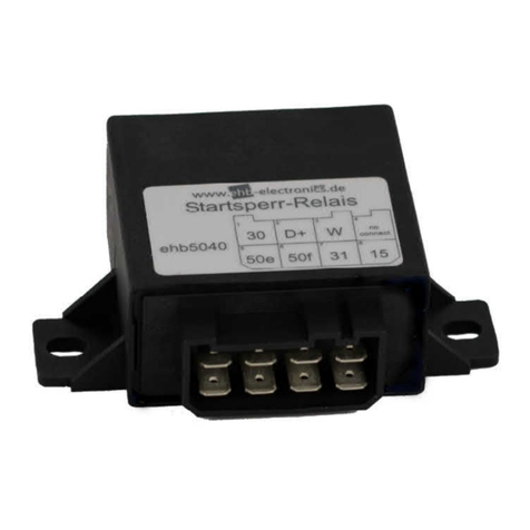
ehb electronics ehb5040 Series User manual

1/10
Vers. 2.4 © ehb errors excepted
Operating Instructions
Start Stop Relay
ehb5040x
Version 2.4
It is not permitted to pass on or copy this documentation or to use or disclose its content unless expressly approved. We reserve the right to recover
damages for any contraventions. All rights are reserved in the case of patent issue or utility model registration.

SSR Operating Instructions
2/10
Vers. 2.4 © ehb errors excepted
Table of Contents
General Information..................................................................................................3
1.1 Target Group ........................................................................................................3
1.2 Important Information for Use ...............................................................................3
1.3 Device Repair .......................................................................................................3
1.4 Product Disposal.......................................................................................................4
Component Description / Function ...........................................................................5
2.1 The following conditions prevent the start-up process: ..............................................5
2.2 The following conditions interrupt the start-up process:.............................................5
2.3 Scope of Protection...................................................................................................5
2.4 Safety Concept..........................................................................................................5
Assembly .................................................................................................................6
Technical Data .........................................................................................................6
Technical Documentation.........................................................................................7
Housing Dimensions ................................................................................................8
Connection Diagram.................................................................................................9
WiringDiagram .........................................................................................................9
Document Information, History ...............................................................................10

SSR Operating Instructions
3/10
Vers. 2.4 © ehb errors excepted
General Information
1.1 Target Group
This documentation is intended for technical service personnel.
1.2 Important Information for Use
Use The device may only be operated with the accessories supplied.
Clean the device with mild cleaning agents only.
Do not insert any objects which were not designed for this specific purpose into the
openings of the device, as this may lead to faults in the electronics.
When operating the device, always observe the general
accident prevention regulations.
Safety Do not operate the SSR within range of strong electromagnetic fields.
Please observe the temperature specifications!
Storage When not in use, the SSR device may only be stored according to the operating
specifications.
Installation During the installation of the device follow the directions of the manufacturers of
plugs and wire harnesses.
Shipping The device may only be shipped in its original packaging or in equally sturdy
packaging.
Use of unsuitable packaging constitutes negligence, whereby any repair under
warranty is forfeited.
Maintenance The SSR requires no maintenance throughout its entire service life and requires
no special care.
Opening the
SSR
The SSR contains no parts that can be maintained, replaced or repaired by the
customer or anyone other than authorised ehb maintenance staff.
1.3 Device Repair
Should a repair be necessary, please send the device to:
ehb electronics gmbh
Hans-Böckler-Str. 20
30851 Langenhagen, Germany
Please ensure that you enclose a written description of the fault(s). This will make it much easier for
the ehb electronics gmbh service department to find the error and return the SSR to you quickly.
Alternatively, use our online service for returning the device: www.ehbservice.de

SSR Operating Instructions
4/10
Vers. 2.4 © ehb errors excepted
NOTE!
ehb electronics gmbh shall only be liable for the professional execution of the work
it performs and for the correct quality of the materials used. Any further claims, such
as compensation for loss of profits and compensation for direct or indirect conse-
quential damages, e.g. loss of data, are excluded.
ATTENTION!
Damages due to improper packaging of the device for shipment and/or interference
by unauthorised persons will invalidate the warranty!
1.4 Product Disposal
Product
Please dispose of the product at the end of its service life in accordance with the applicable
statutory provisions.
Batteries
As the end user, you are legally obliged (pursuant to the German Battery Directive, BattV) to
return all used batteries after use. Batteries may not be disposed of in household waste!
Batteries that contain harmful substances are marked with the symbol shown, which indicates that it is
prohibited for them to be disposed of in household waste. The designations for the determining heavy
metals are:
Cd = cadmium,
Hg = mercury,
Pb = lead.
The relevant designation is marked on the battery, typically beneath the waste bin symbol shown
above. Used batteries can be returned free of charge to collection points provided by
your municipal authority and in outlets where batteries are sold.
In doing so, you are satisfying the legal requirements and contributing towards environmental
protection.
Thank you for observing these rules.

SSR Operating Instructions
5/10
Vers. 2.4 © ehb errors excepted
Component Description / Function
The SSR protects the starter, the pinion and the engine sprocket. It prevents accidental starting when
the engine is already running or when it is still shutting down.
The SSR is an electronic relay that is switched between terminal 30 and the starter (terminal 50f). The
engine speed is measured at terminal W of the alternator. The connections on terminals 15 and 31 are
for supplying power.
The D+ connection is required for some alternators for extra excitation. During the start operation, the
SSR switches on voltage to the D+ connection in parallel with the charging light. This ensures that
even at low speeds, the W terminal provides clear signals for speed detection.
2.1 The following conditions prevent the start-up process:
-
There is already voltage present at input terminal W.
-
- A frequency >=. 4 Hz is measured at input terminal W.
2.2 The following conditions interrupt the start-up process:
- The measured frequency at terminal W exceeds the specified cutoff frequency
-
ehb5040-8 : cutoff frequency 200 Hz
-
ehb5040-4 : cutoff frequency 54 Hz
-
ehb5040-10: cutoff frequency 170 Hz
- No signal is measured or GND is applied to terminal W (line break detection).
2.3 Scope of Protection
-
Start inhibited while the engine is running
-
Start inhibited while the engine is shutting down
-
Restart inhibitor
-
Switch off the starter when the cut-off frequency (e.g. 200 Hz) at terminal W is exceeded
-
Start length is limited to 60sec
2.4 Safety Concept
-
The SSR is plus switching.
-
All outputs are protected against overloading by short circuit detection.
-
In case of overload, the current at the outputs is limited.
-
The output transistors switch off in case of overtemperature.

SSR Operating Instructions
6/10
Vers. 2.4 © ehb errors excepted
-
For switching, the output transistors require a release from the processor and voltage
at input 50e (redundancy).
Assembly
-
Assembly is visible in the engine compartment
-
Use short cables from the ignition start switch and to the starter
-
Protect the SSR from exposure to water and dirt
-
Assemble in a low-vibration location
-
Assemble with the connector side facing downwards
-
Provide sufficient spacing for the connector and cables
Technical Data
Electrical data:
Mechanical data:
Test standard
Voltage range
•
9-36V (typical 12 V to 24 V)
•
No current flow at the outputs with reversed supply
voltage
Power consumption
1 mA at retirement
Securing
Protection against permanent reverse polarity of the
supply voltage
Operating temperature
-20 bis +70 °C
Storage temperature
-30°C to +80°C
Inputs
•
PIN 03 | terminal W
•
PIN 05 | Starter, terminal 50e
Outputs
All outputs short-circuit proof
• PIN 06 | Starter, terminal 50f, 25 A Short circuit cur-
rent limitation 65-180 A
• PIN 02 | D+, 2 A
Housing dimensions (L x H x D)
61 x 31 x 60 mm
Mounting dimensions (L x W x
H)
71 x 95,5 x 35,4 mm
Panel cut-out (W x H)
Twice
6,4 x 8,3mm
Housing material
PA6.6
Weight
78g
Installation
2 x M6 Screws
Degree of protection:
IP 53 / Connection plugs must point downwards
Connection
Plug 8 pin, AMP Positive Lock

SSR Operating Instructions
7/10
Vers. 2.4 © ehb errors excepted
Technical Documentation
EMC tests
EMC test report from an independent
testing laboratory
Measurement of disturbance radiation according to EN 61000-6-3
(VDE 0893, part 6-3): 2002-08
Interference immunity to high-frequency
electromagnetic fields according to IEC 1000-4-3, EN
61000-4-3
(VDE 0847, part 4-3): 2003-11
Interference immunity to transient disturbance variables (bursts)
according to IEC 1000-4-4, EN 61000-4-4
(VDE 0847, part 4-4): 2002-07
Interference immunity to impulse voltages (surges) according to
IEC 1000-4-5, EN 61000-4-5
(VDE 0847, part 4-5): 2001-12
Interference immunity to conducted interference
induced by high-frequency fields according to IEC
1000-4-6, (VDE 0847, part 4-6): 2001-12
CE marking
According to Directive 2014/30/EU

SSR Operating Instructions
8/10
Vers. 2.4 © ehb errors excepted
Housing Dimensions
Relay housing with moulded lugs; dimensions: 60 x 30 x 60 mm; material: PA6.6
31
W
15
50f50e
D+30
95,5 mm
40,7 mm
59,9 mm
61,0 mm
35,4 mm
31,0 mm
60,0 mm
38,2 mm
6,4 mm
82,3 mm
8,3 mm
20,0 mm
24,0 mm
61,0 mm
5,7 mm
25,7 mm
71,0 mm

SSR Operating Instructions
9/10
Vers. 2.4 © ehb errors excepted
Connection Diagram
WiringDiagram

SSR Operating Instructions
10/10
Vers. 2.4 © ehb errors excepted
Document Information, History
Project: SSR
Document type: Technical Documentation
Version: 2.1
Created on: 25.08.2011
Author: ehb electronics gmbh, Langenhagen
Changes:
Version: Edited: On: By:
2.0 Layout adjustment 25.08.2011 O. Howind
2.1 Technical documentation amended 04.10.2011 O. Howind
2.1 Formatting 18.10.2011 Hag
2.1 Error correction 05.01.2012 How/Sch
2.1 Layout adjustment 13.08.2014 Hag
2.2 Adaptation 01.02.2017 Hag
2.3 Adaption Information to use 14.01.2019 Hk/Hag
2.4 Adaption:
2.1 The following conditions prevent the start-up process
2.3 Scope of Protection
2.4 Safety Concept
copyedit
20.08.2020
25.08.2020
Pop
Hag
Imprint
Customer service:
Tel. +49-511-123207- 0
Fax. +49-511-123207-77
Hans-Böckler-Str. 20
30851 Langenhagen, Germany
www.ehb-electronics.de
www.ehbshop.de
www.ehbservice.de
Other manuals for ehb5040 Series
1
This manual suits for next models
3
Table of contents
Other ehb electronics Relay manuals
