manuals.online logo
Brands
  1. Home
  2. •
  3. Brands
  4. •
  5. Zamel
  6. •
  7. Relay
  8. •
  9. Zamel exta PCM-01 User manual

Zamel exta PCM-01 User manual

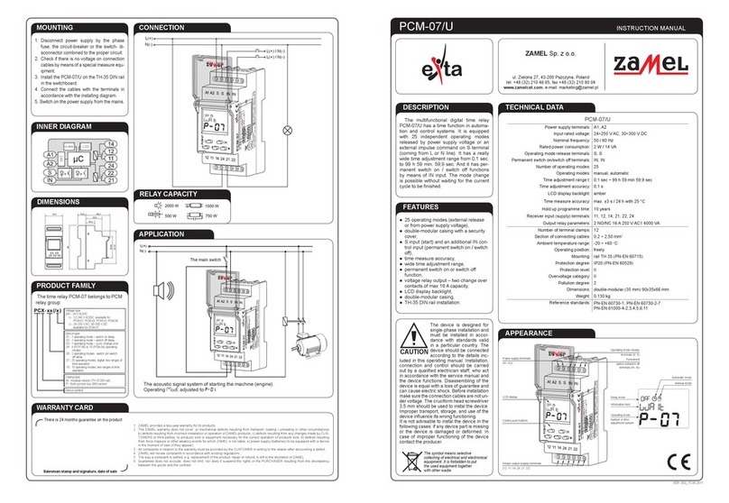
TIME RELAY PCM-01 INSTRUCTION MANUAL
ZAMEL Sp. z o.o.
pcm-01_inst_ext_gb | 03.02.21
APPEARANCE
FEATURES
TECHNICAL PARAMETERS
DESCRIPTION
● Operatingmode:switchondelay(input
voltagerelease),
● supplyvoltagecontrolindicator-LED
green,
● power/relay supply indicator and time
measure-LEDred,
● timemeasureaccuracy,
● widetimeadjustmentrange,
● constantswitchon,switchofffunction,
● relay output - 1 change-over contact
(NO/NC)contactmax16Acapacity,
● TH35DINrailinstallation.
TheonemodetimerelayPCM-01has
a delayed switch on function (reversive)
in automation and control systems. The
relayisreleasedbypowersupplyvoltage.
Ithasawidetimeadjustmentrangefrom
0,1sto10days.AdditionalON/OFFfunc-
tions enable constant switch on, switch
off of the output (load).The system has
theindicatorsofpowersupplyvoltage,re-
laymode,andtimemeasurewiththehelp
ofredLEDdiode.
PCM-01
Input(supply)terminals: L,N
Inputratedvoltage: 230 V AC
Inputvoltagetolerance: -15÷+10%
Supplyvoltagecontrolindicator: LEDgreen
Nominalfrequency: 50/60Hz
Ratedpowerconsumption: 25mA
Operatingmodenumber: 1(switchondelay)
Timeadjustmentranget: from0,1sto10days
Timemeasureaccuracy: 0,2%
Timeadjustment: 2xpotentiometer(rotary+step)
Power/relaysupplyindicatorandtimemeasure: LEDred
Outputrelayparameters: 1NO/NC-16A/250VAC14000VA
Numberofterminalclamps: 5
Sectionofconnectingcables: from0,2to2,50mm2
Ambienttemperaturerange: from-20to+60oC
Operatingposition: free
Mounting: TH35rail(PN-EN60715)
Protectiondegree: IP20(PN-EN60529)
Overvoltagecategory: II
Pollutiondegree: 2
Ratedimpulsewithstandvoltage: 2kV(PN-EN61000-4-5)
Dimensions(height/width/depth): monomodular(17,5mm)90x17,5x66mm
Weight: 0,08kg
ul.Zielona27,43-200Pszczyna,Poland
Tel.+48(32)2104665,Fax+48(32)2108004
www.zamel.com,e-mail:[email protected]
Thedeviceshouldbeconnected
toaone -phasenet workinaccord-
ance with legally binding stand-
ards. The connection method
is described in this manual. Any
activities related to installation,
connection, and adjustment should be per-
formedbyqualiedelectricianswhohaveread
thisuser’smanualandfamiliarisedthemselves
withdevicefunctions.Removingtheenclosure
voidsthewarrantyandposesariskofelectric
shock.Beforeinstallation,makesurethatthere
is no voltage on connection cables. To install
thedevice,useacross-headscrewdriverwith
a diameter of 3.5 mm. The proper operation
of thedeviceis affectedbyhowthedevice is
transported,stored,andused.Itisnotadvis-
abletoinstallthedeviceinthefollowingcases:
lack of any components, damage to or defor-
mationofthedevice.Ifthedeviceoperatesim-
properly,pleasecontactthemanufacturer.
NOTE
Do not dispose of this device together
with other waste! To avoid harmful effects
on the environment and human health,
the worn-out device should be stored
in designated areas. Electrical waste
from households may be handed over
to the waste collector established for
this purpose free of change and in any
amount, as well as to the store when
purchasing new equipment.
Inputsupplyterminals(L,N)
Supplyvoltagecontrolindicator Power/relaysupplyindicator
Smoothtimeadjustment
Timeadjustmentchoice
Output(load)relayterminals(11,12,14)
FUNCTIONING
EXAMPLE OF INSTALLATIONCONNECTING
MOUNTING
1. Disconnectthepowersupplyfromthemains
bythephasefuse,thecircuitbreakerorthe
switch disconnector that are joined to the
propercircuit,
2. Check if there is no voltage on connection
cables by means of a special measure
equipment,
3. InstallPCM-01 deviceintheswitchboard on
TH35DINrail,
4. Connectthecableswiththeterminalsaccord-
ingtoinstallingdiagram,
5. Switchonthepowersupplyfromthemains,
6. AdjustthetimeusingtheTIMEandRANGE
knobs,wheret=TIMExRANGE.
Switchingonthepowersupplyvoltagecaus-
es the green LED luminosity. The cycle wil be
automaticallyinitiatedwiththeadjustedttime.
DIMENSIONS
PRODUCT FAMILY
PCM-01 time relay belongs to PCx time
relayproductfamily.
RELAY CAPACITY
INNER DIAGRAM
U
tt
SWITCHONDELAY-afterthesupplyvoltage[U]hasbeenappliedthe
timemeasuretstarts.Afterthetimeisovertherelayswitcheson(pos.
11-14).
UDiodes’ function
description Time adjustment example t
☼☼☼☼
relayswitchedon(closed
contacts11-14),counting
timeoff 110
5678
9
2
3
4
T
I
M
E
0,1s OFF
1s
10s
1min
10min 1h 10h
1d
ON
R
A
N
G
E
t = TIMExRANGE,
t=8x1d=8d
☼☼☼☼relayswitchedoff(closed
contacts11-12)counting
time on
T
I
M
E
110
567
8
9
2
34
0,1s OFF
1s
10s
1min
10min
1h
10h
1d
ON
R
A
N
G
E
t = TIMExRANGE,
t=3x1h=3h
Warning system before the motor starts up.
PCM-01timerelayworksinthesystemwhereafterpushingtheSTART/STOPbuttonawarningacous-
ticsignalisheardtoinformthemotorisjusttostartup.ThisrelaycooperateswithPCM-04inbistable
relaymodewithlimitedtime(MODE=I),itenablestoswitchon/offtheenginebymeansofonebutton
aswellastosetmaxpossibleworkingtime.
GUARANTEE CARD
Thereis24monthsguaranteeontheproduct
Salesman stamp and signature, date of sale
Voltagetype:
24V-24VAC/DC
U-12÷240VAC/DC:available for
PCM-01, PCM-02, PCM-03, PCM-06
U-24÷250VAC;30÷300VDC:
availablefor PCM-07
Devicetype:
01-1operatingmode–switchondelay
02-1operatingmode–switchoffdelay
03-1operatingmode–cyclicchangeover
04-8(PCP-04)or10(PCM-04)operating
modes
06-2operatingmodes-switchon/switch
offdelay
07-25operatingmodes,digital,tworangesof
timeoperation
10-10operatingmodes,tworangesoftime
operation
Casingtype:
M-modularversion(TH35DINrail)
P-ushjunctionboxØ60version
Devicesymbol
1.ZAMELSp.zo.o.shalloffera24-monthwarrantyontheproductssold.
2.ThewarrantyprovidedbyZAMELSp.zo.o.shallnotcover:
a)mechanicaldamagecausedduringtransport,loading/unloadingorinothercircumstances,
b)damagecausedbyincorrectinstallationoroperationofproductsmanufacturedbyZAMELSp.zo.o.,
c)damageresultingfromanychangesmadebytheBUYERorthirdpartiesintheproductssoldorequipmentnecessaryforthe
properoperationoftheproductssold,
d)damageresultingfromforcemajeureorotherfortuitouseventsforwhichZAMELSp.zo.o.isnotliable.
3.AnywarrantyclaimsshallbemadebytheBUYERatthepointofsaleortoZAMELzo.o.inwritingafterdefectshavebeenidenti-
ed.
4.ZAMELSp.zo.o.undertakestohandlecomplaintsinaccordancewiththeapplicableprovisionsofPolishlaw.
5.Thechoiceoftheformofcomplainresolution,e.g.replacementofaproductwithaproductfreefromdefects,repair,orreimburse-
mentofmoney,shallliewithZAMELSp.zo.o.
6.Thewarrantydoesnotexclude,limit,orsuspendBUYER’srightsunderthestatutorywarrantyfordefectsintheitemsold.
NL
11
12
14
µC
A/C
START/STOP

Other Zamel Relay manuals

Zamel exta PPM - 05 User manual

Zamel

Zamel exta PPM - 05 User manual

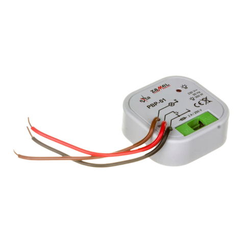
Zamel EXTA PBP-01 User manual

Zamel

Zamel EXTA PBP-01 User manual

Zamel PCM-04/24V User manual

Zamel

Zamel PCM-04/24V User manual

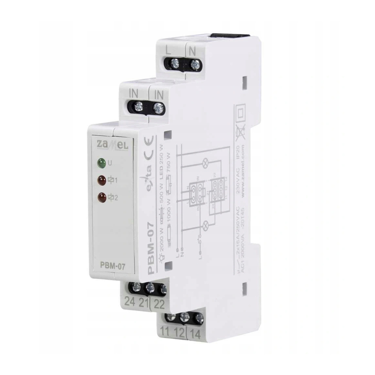
Zamel exta PBM-07 User manual

Zamel

Zamel exta PBM-07 User manual

Zamel Exta PCM-02/U User manual

Zamel

Zamel Exta PCM-02/U User manual

Zamel exta PCM-09 User manual

Zamel

Zamel exta PCM-09 User manual

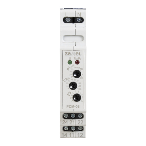
Zamel PCM-08 User manual

Zamel

Zamel PCM-08 User manual

Zamel exta PB Series User manual

Zamel

Zamel exta PB Series User manual

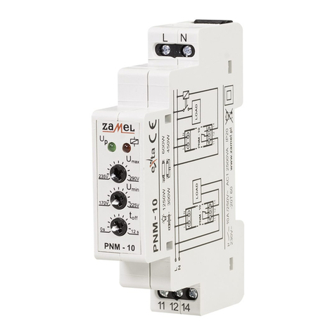
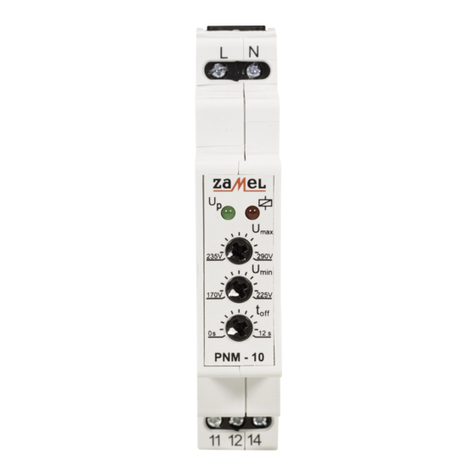
Zamel PNM-10 User manual

Zamel

Zamel PNM-10 User manual

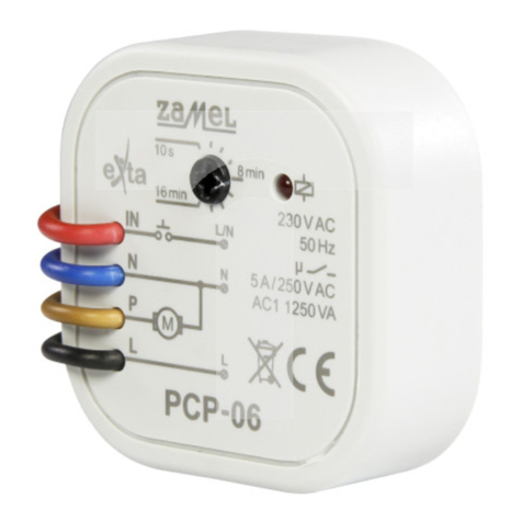
Zamel EXTA PCP-06 User manual

Zamel

Zamel EXTA PCP-06 User manual

Zamel EXTA PCM-11 User manual

Zamel

Zamel EXTA PCM-11 User manual

Zamel Exta PBM-07 User manual

Zamel

Zamel Exta PBM-07 User manual

Zamel PCM-07/U User manual

Zamel

Zamel PCM-07/U User manual

Zamel EXTA PBM-03 User manual

Zamel

Zamel EXTA PBM-03 User manual

Zamel PNM-32 User manual

Zamel

Zamel PNM-32 User manual

Zamel Exta PBM-04/U User manual

Zamel

Zamel Exta PBM-04/U User manual

Zamel exta PNM-10 User manual

Zamel

Zamel exta PNM-10 User manual

Zamel PCM-02/24V User manual

Zamel

Zamel PCM-02/24V User manual

Zamel EXT10000084 User manual

Zamel

Zamel EXT10000084 User manual

Zamel EXTA PBM-02 User manual

Zamel

Zamel EXTA PBM-02 User manual

Zamel Exta PBM-03 User manual

Zamel

Zamel Exta PBM-03 User manual

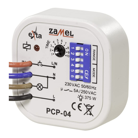
Zamel EXTA PCP-04 User manual

Zamel

Zamel EXTA PCP-04 User manual

Zamel PBM-01 User manual

Zamel

Zamel PBM-01 User manual

Popular Relay manuals by other brands

Lightwave LW821 instruction manual

Lightwave

Lightwave LW821 instruction manual

Bin Master VF-90 operating instructions

Bin Master

Bin Master VF-90 operating instructions

Pilz PNOZ X2C operating manual

Pilz

Pilz PNOZ X2C operating manual

Kyongbo Electronics GDR-JD01 user manual

Kyongbo Electronics

Kyongbo Electronics GDR-JD01 user manual

Pilz P1HZ X1 operating manual

Pilz

Pilz P1HZ X1 operating manual

enphase Q Relay Installation

enphase

enphase Q Relay Installation

CARLO GAVAZZI RSGT manual

CARLO GAVAZZI

CARLO GAVAZZI RSGT manual

Pilz PNOZ X Series operating instructions

Pilz

Pilz PNOZ X Series operating instructions

Eaton PKE-XZMR Series Instruction leaflet

Eaton

Eaton PKE-XZMR Series Instruction leaflet

Pilz 21 396-04 operating instructions

Pilz

Pilz 21 396-04 operating instructions

Vega VEGAMIP R61 operating instructions

Vega

Vega VEGAMIP R61 operating instructions

Rockwell Automation Allen-Bradley Guardmaster 440C-CR30 Wiring diagram

Rockwell Automation

Rockwell Automation Allen-Bradley Guardmaster 440C-CR30 Wiring diagram

ComAp NPU Installation and operation instructions

ComAp

ComAp NPU Installation and operation instructions

Extreme Max 5600.3060 Quick start quide

Extreme Max

Extreme Max 5600.3060 Quick start quide

Boutronic JGA2011 manual

Boutronic

Boutronic JGA2011 manual

ABB CVQ Instruction leaflet

ABB

ABB CVQ Instruction leaflet

Woodward EM80 Software update procedure

Woodward

Woodward EM80 Software update procedure

Robertshaw 83939-D Series manual

Robertshaw

Robertshaw 83939-D Series manual

manuals.online logo
manuals.online logoBrands
  • About & Mission
  • Contact us
  • Privacy Policy
  • Terms and Conditions

Copyright 2025 Manuals.Online. All Rights Reserved.