EHRHORN Alpha 5841 User manual

Ehrhorn Technotogical Operations, Inc.
4975 North 30th Street
Colora o Springs, CO 80919
OPERATING AND TECHNICAL MANUAL
HIGH FREQUENCY LINEAR POWER AMPLIFIERS
MODELS PA-76, PA-76P, and PA-76C
EHRHORN TECHNOLOGICAL OPERATIONS, INC.
R vis d May 1, 1977
TABLE OF CONTENTS
SECTION 1
SECTION 2
SECTION 3
SECTION k -
SECTION 5 -
SECTION 6 -
ET0/"ALPHA"
- G n ral D scription and Sp cifications
■ INSTALLATION
High Voltag Tap S l ction
...............
3
Int rconn ctions With Oth r Equipm nt . . . 4
• OPERATION 5
Initial Tun -Up
........................
6
Op ration At 1 KW and 2 KW Input
.........
7
ALPHA 76P and ALPHA 7&C Op rating Diff r nc s 8
Op rating Not s
........................
9
Troubl shooting Hints
..................
10
THEORY OF OPERATION
....................
11
ILLUSTRATIONS
..........................
13
Transform r Installation or R moval . . . . 13
R ar V i w
.............................. 13
Top Vi w Showing Major Compon nt Locations . 14
Sch matic Diagram
......................
15
Front Pan l V i w
...............
Front Cov r
STANDARD ELECTRICAL PARTS
...............
16
PRODUCTS WARRANTY
...............
Back Cov r
EHRHORN TECHNOLOGICAL OPERATIONS, INC.
CANON CITY, COLORADO 81212
5/77 U.S.A.

Th ALPHA 76 (mod l PA-76) is a s lf-contain d high fr qu ncy lin
ar pow r amplifi r capabl of continuous op ration at d-c plat
pow r inputs of 2.5 kilowatts PEP for SSB voic and on kilowatt
av rag or continuous carri r with no tim limit (NTL). Th ALPHA
76 is tunabl ov r th rang 1.8-2.0 MHz plus 3_3° MHz, optimiz d
for conv ni nc in th six amat ur bands of 10 through 160 m t rs.
SPECIFICATIONS (Mod l PA-76)
Fr qu ncy Cov rag : 1.8-2.0 and 3-30 MHz (including 10-160 m t rs).
Plat Pow r Input; 2.5 KW PEP/SSB, 1 KW av rag or k y down, CCS.
RF Pow r Output: Typically 1.5 KW PEP/SSB, 650 watts carri r, CCS.
Driv Pow rs Nominal 100 watts PEP, 60 watts carri r.
Input & Output Imp danc s; Nominal 50 ohms r sistiv , unbalanc d;
VSWR 2:1 or l ss.
Distortion: Third ord r IM mor than 30 3b b low 1 KW PEP output.
Harmonics : Mor than 50 db b low m an fundam ntal fr qu ncy output.
Tub Compl m nt; Two Eimac 88?^ c ramic-m tal ground d-grid triod s.
Cooling: Full-cabin t, duct d forc d air; c ntrifugal blow r.
ALC: Adjustabl thr shold, n gativ -going standard as shipp d.
Prot ction: Primary fus s, plat ov rcurr nt r lay, AC and HV
int rlocks.
Primary Pow r: 24QV/10A or 120V/20A, nominal, 50-60 Hz.
Siz and W ight: 7.5"h. x 17"w. x l4.75"d. Shipping wt., 75 lb.
Optional Modifications Availabl :
Lightw ight Hip rsir^ pow r transform r r duc s
n t and shipping w ights by approximat ly 20 lb.
HI/LO (or "SSB/CW-TUNE”) tap chang r lay, front
pan l controll d.
Id ntical with PA-76 abov xc pt tub compl m nt
is thr 8874's, incr asing plat pow r input rat
ing to 3+ KW PEP and typical rf output to 2 KW PEP.
Do s not aff ct long t rm av rag or continuous
pow r ratings.
"Comm rcial" mod l id ntical with PA-76 xc pt
tub compl m nt is thr 8874' pow r transfor
m r is sp cial 2.4 KVA Hip rsir^, and option "R"
is standard. PEP ratings, d-c input 3 KW, typi
cal rf output 2 KW; continuous carri r or long
t rm av rag ratings, d-c input 1.6 KW, rf output
1 KW CCS (RATT, A0, tc.)
-1-
SECTION 1
GENERAL DESCRIPTION
Option "L" --
Option "R" --
Mod l 76? --
Mod l 76C --
2-
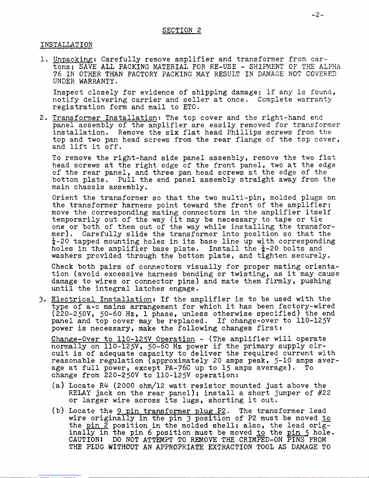
Unpacking: Car fully r mov amplifi r and transform r from car
tons; SAVE ALL PACKING MATERIAL FOR RE-USE - SHIPMENT OF THE ALPHA
76 IN OTHER THAN FACTORY PACKING MAY RESULT IN DAMAGE NOT COVERED
UNDER WARRANTY.
Insp ct clos ly for vid nc of shipping damag ; if any is found,
notify d liv ring carri r and s ll r at onc . Compl t warranty
r gistration form and mail to ETO.
2. Transform r Installation; Th top cov r and th right-hand nd
pan l ass mbly of th amplifi r ar asily r mov d for transform r
installation. R mov th six flat h ad Phillips scr ws from th
top and two pan h ad scr ws from th r ar flang of th top cov r,
and lift it off.
To r mov th right-hand sid pan l ass mbly, r mov th two flat
h ad scr ws at th right dg of th front pan l, two at th dg
of th r ar pan l, and thr pan h ad scr ws at th dg of th
bottom plat . Pull th nd pan l ass mbly straight away from th
main chassis ass mbly.
Ori nt th transform r so that th two multi-pin, mold d plugs on
th transform r harn ss point toward th front of th amplifi r;
mov th corr sponding mating conn ctors in th amplifi r its lf
t mporarily out of th way (it may b n c ssary to tap or ti
on or both of th m out of th way whil installing th transfor
m r) . Car fully slid th transform r into position so that th
i-20 tapp d mounting hol s in its bas lin up with corr sponding
hol s in th amplifi r bas plat . Install th J-20 bolts and
wash rs provid d through th bottom plat , and tight n s cur ly.
Ch ck both pairs of conn ctors visually for prop r mating ori nta
tion (avoid xc ssiv harn ss b nding or twisting, as it may caus
damag to wir s or conn ctor pins) and mat th m firmly, pushing
until th int gral latch s ngag .
3» El ctrical Installation: If th amplifi r is to b us d with th
typ of a-c mains arrang m nt for which it has b n factory-wir d
(220-250V, 50-60 Hz, 1 phas , unl ss oth rwis sp cifi d) th nd
pan l and top cov r may b r plac d. If chang -ov r to 110-125V
pow r is n c ssary, mak th following chang s first:
Chang -Ov r to 110-125V Op ration - (Th amplifi r will op rat
normally on 110-125V, 50-60 Hz pow r if th primary supply cir
cuit is of ad quat capacity to d liv r th r quir d curr nt with
r asonabl r gulation (approximat ly 20 amps p ak, 5-10 amps av r
ag at full pow r, xc pt PA-76C up to 15 amps av rag ). To
chang from 220-250V to 110-125V op ration:
(a) Locat R4 (2000 ohm/12 watt r sistor mount d just abov th
RELAY jack on th r ar pan l); install a short jump r of #22
or larg r wir across its lugs, shorting it out.
(b) Locat th 9 pin transform r plug P2. Th transform r l ad
wir originally in th pin 3 position of P2 must b mov d tc>
th pin 2 position in th mold d sh ll? also, th l ad orig
inally in th pin 6 position must b mov d to th pin 5 hol .
CAUTION! DO NOT ATTEMPT TO REMOVE THE CRIMPED-ON PINS FROM
THE PLUG WITHOUT AN APPROPRIATE EXTRACTION TOOL AS DAMAGE TO
SECTION 2
INSTALLATION
I
3
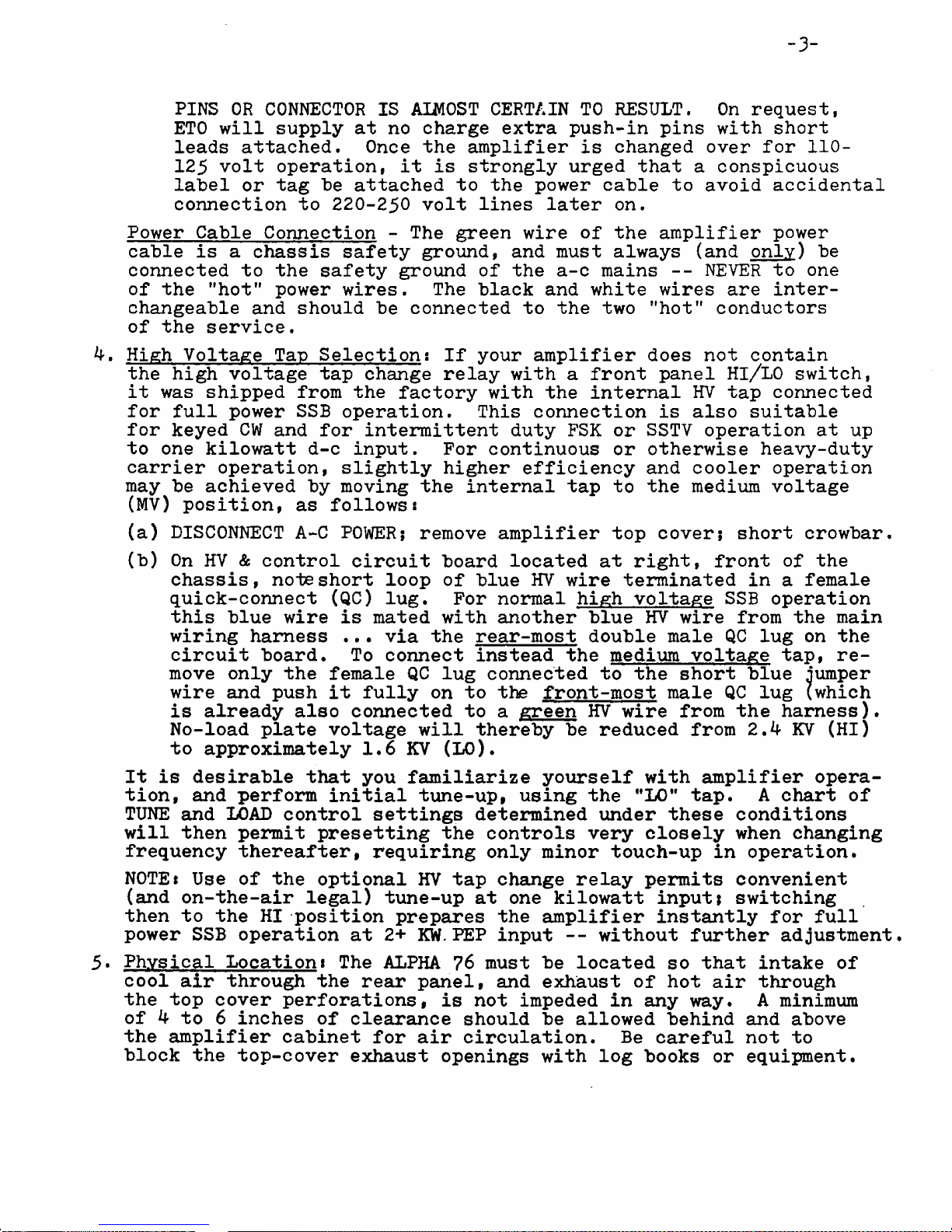
PINS OR CONNECTOR IS AIMOST CERTAIN TO RESULT. On r qu st,
ETO will supply at no charg xtra push-in pins with short
l ads attach d. Onc th amplifi r is chang d ov r for 110-
125 volt op ration, it is strongly urg d that a conspicuous
lab l or tag b attach d to th pow r cabl to avoid accid ntal
conn ction to 220-250 volt lin s lat r on.
Pow r Cabl Conn ction - Th gr n wir of th amplifi r pow r
cabl is a chassis saf ty ground, and must always (and only) b
conn ct d to th saf ty ground of th a-c mains -- NEVER to on
of th "hot" pow r wir s. Th black and whit wir s ar int r
chang abl and should b conn ct d to th two "hot" conductors
of th s rvic .
4. High Voltag Tap S l ction: If your amplifi r do s not contain
th high voltag tap chang r lay with a front pan l Hl/LO switch,
it was shipp d from th factory with th int rnal HV tap conn ct d
for full pow r SSB op ration. This conn ction is also suitabl
for k y d CW and for int rmitt nt duty FSK or SSTV op ration at up
to on kilowatt d-c input. For continuous or oth rwis h avy-duty
carri r op ration, slightly high r ffici ncy and cool r op ration
may b achi v d by moving th int rnal tap to th m dium voltag
(MV) position, as follows:
(a) DISCONNECT A-C POWER; r mov amplifi r top cov r; short crowbar.
(b) On HV & control circuit board locat d at right, front of th
chassis, not short loop of blu HV wir t rminat d in a f mal
quick-conn ct (QC) lug. For normal high voltag SSB op ration
this blu wir is mat d with anoth r blu HV wir from th main
wiring harn ss ..• via th r ar-most doubl mal QC lug on th
circuit board. To conn ct inst ad th m dium voltag tap, r
mov only th f mal QC lug conn ct d to th short blu jump r
wir and push it fully on to th front-most mal QC lug (which
is alr ady also conn ct d to a gr n HV wir from th harn ss).
No-load plat voltag will th r by b r duc d from 2.4 KV (HI)
to approximat ly 1.6 KV (LO).
It is d sirabl that you familiariz yours lf with amplifi r op ra
tion, and p rform initial tun -up, using th "L O ” tap. A chart of
TUNE and LOAD control s ttings d t rmin d und r th s conditions
will th n p rmit pr s tting th controls v ry clos ly wh n changing
fr qu ncy th r aft r, r quiring only minor touch-up in op ration.
NOTE* Us of th optional HV tap chang r lay p rmits conv ni nt
(and on-th -air l gal) tun -up at on kilowatt input; switching
th n to th HI position pr par s th amplifi r instantly for full
pow r SSB op ration at 2+ KW. PEP input -- without furth r adjustm nt.
5* Physical Locationt Th ALPHA 76 must b locat d so that intak of
cool air through th r ar pan l, and xhaust of hot air through
th top cov r p rforations, is not imp d d in any way. A minimum
of 4 to 6 inch s of cl aranc should b allow d b hind and abov
th amplifi r cabin t for air circulation. B car ful not to
block th top-cov r xhaust op nings with log books or quipm nt.

4
6. RF And Control Conn ctions : Int rconn ction of th ALPHA 76 for
op ration with any popular transc iv r or xcit r is xtr m ly
simpl . Conn ct th r ar pan l jacks as follows:
RF INPUT - Us a standard "RCA" typ plug and RG-58C/U or similar
small 50 ohm coaxial cabl to conn ct to transc iv r or xcit r
"rf output” or ’’ant nna" conn ctor. K p cabl short if possibl .
RF OUTPUT - Us a standard PL-259 ("UHF" typ ) plug and RG-8A/U
or similar 50 ohm coaxial cabl to conn ct to ant nna syst m.
RELAY - Us a standard "phono-typ " patch cabl to conn ct this
jack to contacts which ar "op n" on r c iv and "short d" on
transmit ("N.O." -- normally op n). Such contacts ar usually
availabl on th r ar pan l of th xcit r or transc iv r in th
form of a matching "phono" conn ctor. A f w transc iv rs, such
as Atlas and Drak uni*t^ may r quir sp cial conn ctors for
tying into th ir int rnal transmit-r c iv r lay contacts.
NOTE: Wh n th amplifi r is OFF or in th RECEIVE condition with
no short across th RELAY lin , th RF OUTPUT conn ctor is int rnally
conn ct d dir ctly to th RF INPUT conn ctor, providing normal
"transc iv -typ " ant nna input to th r c iv r.
ALC - For us with conv ntional transc iv rs having n gativ -
going ALC syst ms, simply patch this jack to th mating ALC jack
on th transc iv r (or xcit r), using standard "phono” cabl .
C rtain solid-stat transc iv rs utiliz positiv -going ALC which
r quir s slight modification of th amplifi r's ALC circuit, or
us of an adapt r, if ALC f dback is to b mploy d. Normally
it is quit satisfactory to simply us th transc iv r's int rnal
ALC syst m with Atlas, Triton, and similar radios.
-5-
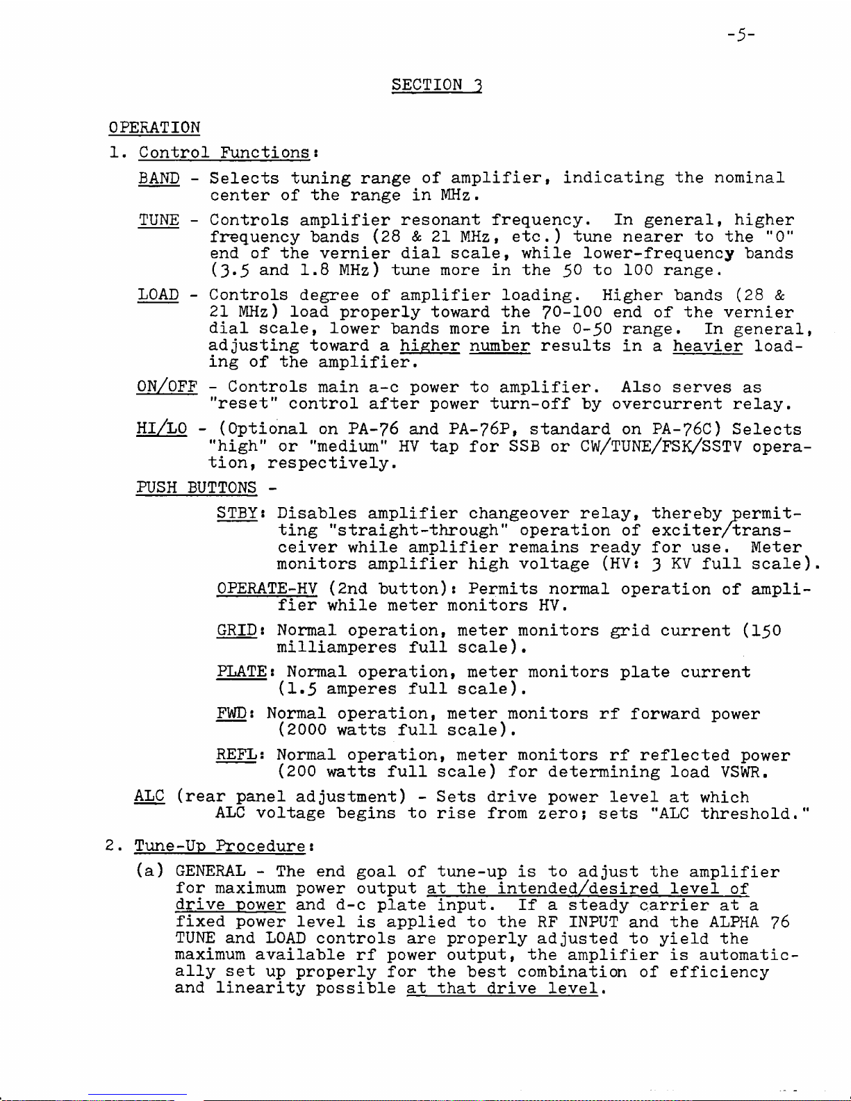
1. Control Functions:
BAND - S l cts tuning rang of amplifi r, indicating th nominal
c nt r of th rang in MHz.
TUNE - Controls amplifi r r sonant fr qu ncy. In g n ral, high r
fr qu ncy bands (28 & 21 MHz, tc.) tun n ar r to th ”0"
nd of th v rni r dial scal , whil low r-fr qu ncy bands
(3*5 and 1.8 MHz) tun mor in th 50 to 100 rang .
LOAD - Controls d gr of amplifi r loading. High r bands (28 &
21 MHz) load prop rly toward th 70-100 nd of th v rni r
dial scal , low r bands mor in th 0-50 rang . In g n ral,
adjusting toward a high r numb r r sults in a h avi r load
ing of th amplifi r.
ON/OFF - Controls main a-c pow r to amplifi r. Also s rv s as
"r s t" control aft r pow r turn-off by ov rcurr nt r lay.
Hl/LO - (Optional on PA-76 and PA-76P, standard on PA-76C) S l cts
"high" or "m dium" HV tap for SSB or CW/TUNE/FSK/SSTV op ra
tion, r sp ctiv ly.
PUSH BUTTONS -
STBY: Disabl s amplifi r chang ov r r lay, th r by p rmit
ting "straight-through" op ration of xcit r/trans
c iv r whil amplifi r r mains r ady for us . M t r
monitors amplifi r high voltag (HV: 3 KV full scal ).
OPERATE-HV (2nd button): P rmits normal op ration of ampli
fi r whil m t r monitors HV.
GRID: Normal op ration, m t r monitors grid curr nt (150
milliamp r s full scal ).
PLATE: Normal op ration, m t r monitors plat curr nt
(1.5 amp r s full scal ).
FWD: Normal op ration, m t r monitors rf forward pow r
(2000 watts full scal ).
REFL: Normal op ration, m t r monitors rf r fl ct d pow r
(200 watts full scal ) for d t rmining load VSWR.
ALC (r ar pan l adjustm nt) - S ts driv pow r l v l at which
ALC voltag b gins to ris from z ro; s ts "ALC thr shold."
2. Tun -Up Proc dur :
(a) GENERAL - Th nd goal of tun -up is to adjust th amplifi r
for maximum pow r output at th int nd d/d sir d l v l of
driv pow r and d-c plat input. If a st ady carri r at a
fix d pow r l v l is appli d to th RF INPUT and th ALPHA 76
TUNE and LOAD controls ar prop rly adjust d to yi ld th
maximum availabl rf pow r output, th amplifi r is automatic
ally s t up prop rly for th b st combination of ffici ncy
and lin arity possibl at that driv l v l.
SECTION 3
OPERATION

-6-
If th driv pow r is incr as d b yond th tun -up l v l
aft r th final TUNE/LOAD adjustm nts, flattopping and un
d sirabl distortion (on SSB) will r sult, along with grid
curr nt gr atly in xc ss of normal.
If driv pow r is r duc d b low th tun -up l v l without fur
th r adjustm nt of TUNE and LOAD controls, amplifi r ffici ncy
will b r duc d. Both of th s stat m nts ar applicabl to
any lin ar amplifi r of th typ s us d for high pow r amat ur
and similar s rvic .
It is th r for ss ntial that th amplifi r b adjust d for
maximum rf output at th driv and d-c input pow rs which ar
to b mploy d in normal op ration, WITH ONE IMPORTANT EXCEPTION:
if th plat voltag is chang d without changing also th TUNE
and LOAD adjustm nts, th r sulting pow r l v l which will yi ld
optimum p rformanc at th n w plat voltag will vary in pro
portion to th squar of th plat voltag chang . For xampl ,
if th ALPHA 76 is tun d up for maximum output with 1400 VDC
plat voltag and with th driv l v l s t so that th r sult
ant maximum output is about 700 watts ( quival nt to a d-c
input of roughly 1000 watts), THEN if th plat voltag is
incr as d to 2000 VDC th amplifi r will automatically p rform
optimally at about 700 X (2000/1400)2 = 1400 watts rf output,
corr sponding to approximat ly 2000 watts d-c input.
In g n ral, th final op rating adjustm nt aft r basic tun -
up should b to adjust xcitation (driv ) from th xcit r or
transc iv r so that th GRID curr nt m t r indication just
r ach s about 50 mad (l/3 scal ) k y-down or on voic p aks.
(b) INITIAL TUNE-UP - S l ct m dium plat voltag by ith r placing
th pan l switch controlling th (optional) HV tap chang r lay
into its L0 (down) position or s l cting th int rnal MV tap
b for installing th amplifi r cov r during installation.. Mak
c rtain that th top cov r is prop rly fast n d in plac .
(1) Pr ss STBY button and mom ntarily lift th ON toggl .
Th pan l m t r should imm diat ly illuminat r d or
amb r and indicat 1,5 KV (mid-scal ) + 100 V. Th
blow r should start imm diat ly and xhaust air should
b r adily d t ctabl flowing from th top cov r v nts.
(2) Wh n th tub warm-up d lay is compl t d in 45 to 90
s conds, th m t r will chang from amb r to pal gr n,
indicating ’’r ady" to transmit. S t controls to th pr
liminary points indicat d in Tabl I b low, d p nding
on th d sir d op rating fr qu ncy.
TABLE I -- PRELIMINARY SETTINGS FOR INITIAL TUNE-UP
FREQ.. MHZ
1.8 BAND TUNE LOAD FREQ. BAND TUNE LOAD
1.8 84 30 7.1 7 50 45
2.0 1.8 75 25 14.15 14 21 70
3.6 3.5 53 38 21.20 21 10 82
3.9 3.5 42 48 28.70 28 08 85
(3) Pr ss PLATE button and switch xcit r to CW or TUNE;
th pan l m t r should turn amb r to indicat 'transmit.'
7
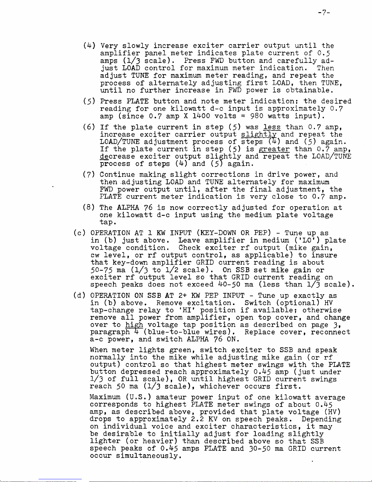
(4) V ry slowly incr as xcit r carri r output until th
amplifi r pan l m t r indicat s plat curr nt of 0.5
amps (1/3 scal ). Pr ss FWD button and car fully ad
just LOAD control for maximum m t r indication. Th n
adjust TUNE for maximum m t r r ading, and r p at th
proc ss of alt rnat ly adjusting first LOAD, th n TUNE,
until no furth r incr as in FWD pow r is obtainabl .
(5) Pr ss PLATE button and not m t r indication; th d sir d
r ading for on kilowatt d-c input is approximat ly 0.7
amp (sinc 0.7 amp X 1400 volts = 980 watts input).
(6) If th plat curr nt in st p (5) was l ss than 0.7 amp,
incr as xcit r carri r output slightly and r p at th
LOAD/TUNE adjustm nt proc ss of st ps (4) and (5) again.
If th plat curr nt in st p (5) is gr at r than 0.7 amp,
d cr as xcit r output slightly and r p at th LOAD/TUNE
proc ss of st ps (4) and (5) again.
(7) Continu making slight corr ctions in driv pow r, and
th n .adjusting LOAD and TUNE alt rnat ly for maximum
FWD pow r output until, aft r th final adjustm nt, th
PLATE curr nt m t r indication is v ry clos to 0,7 amp.
(8) Th ALPHA 76 is now corr ctly adjust d for op ration at
on kilowatt d-c input using th m dium plat voltag
tap.
(c) OPERATION AT 1 KW INPUT (KEY-DOWN OR PEP) - Tun up as
in (b) just abov . L av amplifi r in m dium ('LO*) plat
voltag condition. Ch ck xcit r rf output (mik gain,
cw l v l, or rf output control, as applicabl ) to insur
that k y-down amplifi r GRID curr nt r ading is about
50-75 ma (1/3 to l/2 scal ). On SSB s t mik gain or
xcit r rf output l v l so that GRID curr nt r ading on
sp ch p aks do s not xc d 40-50 ma (l ss than 1/3 scal ).
(d) OPERATION ON SSB AT 2+ KW PEP INPUT - Tun up xactly as
in (b) abov . R mov xcitation. Switch (optional) HV
tap-chang r lay to 'HI* position if availabl ; oth rwis
r mov all pow r from amplifi r, op n top cov r, and chang
ov r to high voltag tap position as d scrib d on pag 3i
paragraph 4 (blu -to-blu wir s). R plac cov r, r conn ct
a-c pow r, and switch ALPHA 76 ON,
Wh n m t r lights gr n, switch xcit r to SSB and sp ak
normally into th mik whil adjusting mik gain (or rf
output) control so that high st m t r swings with th PLATE
button d pr ss d r ach approximat ly 0.45 amp (just und r
l/3 of full scal ), OR until high st GRID curr nt swings
r ach 50 ma (1/3 scal ), which v r occurs first.
Maximum (U.S.) amat ur pow r input of on kilowatt av rag
corr sponds to high st PLATE m t r swings of about 0.45
amp, as d scrib d abov , provid d that plat voltag (HV)
drops to approximat ly 2.2 KV on sp ch p aks. D p nding
on individual voic and xcit r charact ristics, it may
b d sirabl to initially adjust for loading slightly
light r (or h avi r) than d scrib d abov so that SSB
sp ch p aks of 0.45 amps PLATE and 30-5° ma GRID curr nt
occur simultan ously.
I
8
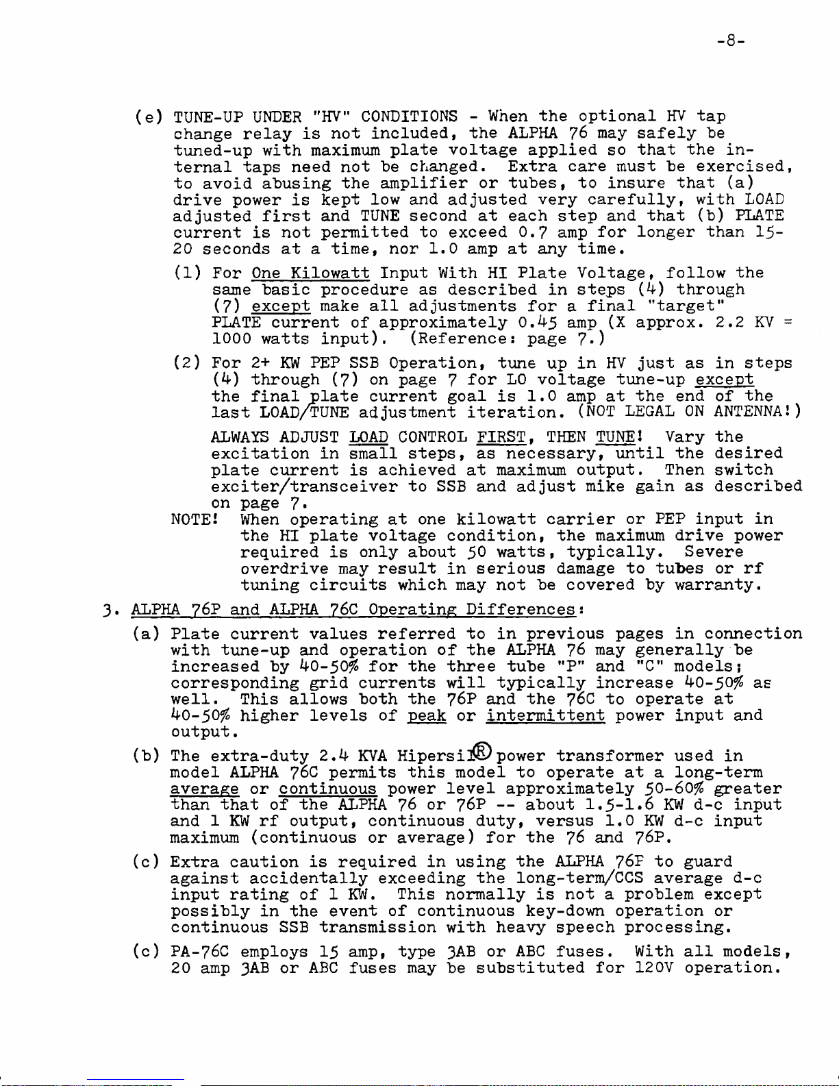
( ) TUNE-UP UNDER "HV" CONDITIONS - Wh n th optional HV tap
chang r lay is not includ d, th ALPHA 76 may saf ly "b
tun d-up with maximum plat voltag appli d so that th in
t rnal taps n d not b chang d. Extra car must b x rcis d,
to avoid abusing th amplifi r or tub s, to insur that (a)
driv pow r is k pt low and adjust d v ry car fully, with LOAD
adjust d first and TUNE s cond at ach st p and that (b) PLATE
curr nt is not p rmitt d to xc d 0.7 amp for long r than 15-
20 s conds at a tim , nor 1.0 amp at any tim .
(1) For On Kilowatt Input With HI Plat Voltag , follow th
sam basic proc dur as d scrib d in st ps (4) through
(7) xc pt mak all adjustm nts for a final "targ t"
PLATE curr nt of approximat ly 0.45 amp (X approx. 2.2 KV =
1000 watts input). (R f r nc : pag 7*)
(2) For 2+ KW PEP SSB Op ration, tim up in HV just as in st ps
(4) through (7) on pag 7 for L0 voltag tun -up xc pt
th final plat curr nt goal is 1.0 amp at th nd of th
last LOAD/TUNE adjustm nt it ration. (NOT LEGAL ON ANTENNA!)
ALWAYS ADJUST LOAD CONTROL FIRST, THEN TUNE! Vary th
xcitation in small st ps, as n c ssary, until th d sir d
plat curr nt is achi v d at maximum output. Th n switch
xcit r/transc iv r to SSB and adjust mik gain as d scrib d
on pag 7«
NOTE! Wh n op rating at on kilowatt carri r or PEP input in
th HI plat voltag condition, th maximum driv pow r
r quir d is only about 50 watts, typically. S v r
ov rdriv may r sult in s rious damag to tub s or rf
tuning circuits which may not b cov r d by warranty.
3* ALPHA 76P and ALPHA 76C Op rating Diff r nc s:
(a) Plat curr nt valu s r f rr d to in pr vious pag s in conn ction
with tun -up and op ration of th ALPHA 76 may g n rally b
incr as d by 40-50# for th thr tub "P" and "C" mod ls;
corr sponding grid curr nts will typically incr as 40-50$ as
w ll. This allows both th 76P and th 76C to op rat at
40-50$ high r l v ls of p ak or int rmitt nt pow r input and
output.
(b) Th xtra-duty 2.4 KVA Hip rsi3®pow r transform r us d in
mod l ALPHA 76C p rmits this mod l to op rat at a long-t rm
av rag or continuous pow r l v l approximat ly 50-60$ gr at r
than that of th ALPHA 76 or 76P — about 1.5-1«6 KW d-c input
and 1 KW rf output, continuous duty, v rsus 1.0 KW d-c input
maximum (continuous or av rag ) for th 76 and 76P.
(c) Extra caution is r quir d in using th ALPHA 76P to guard
against accid ntally xc ding th long-t rm/CCS av rag d-c
input rating of 1 KW. This normally is not a probl m xc pt
possibly in th v nt of continuous k y-down op ration or
continuous SSB transmission with h avy sp ch proc ssing.
(c) PA-76C mploys 15 amp, typ 3AB or ABC fus s. With all mod ls,
20 amp 3AB or ABC fus s may b substitut d for 120V op ration.

-9
4. Op rating Not s:
(a) TUBES - Th 8874 c ramic triod s ar xtr m ly rugg d and
normally op rat with a larg margin of saf ty. Th y will
d liv r outstanding s rvic lif IF not damag d by grossly
xc ssiv grid dissipation or airflow blockag (k p th
intak and xhaust v nt ar as cl ar!) Do not allow av rag
plat curr nt p r tub to xc d 0.35 amp for mor than 15-
30 s conds, nor v r to xc d 0.5 amp. Do not allow grid
curr nt to v r xc d full scal (150 ma); normal op ration
r quir s only 50-60 ma.
(b) INTERLOCKS - Th ALPHA 76 (all v rsions) is quipp d with
switch s which shut off a-c pow r and short out th high
voltag pow r supply wh n th cov r is not s cur ly fast n d
in plac . THESE PROTECTIVE INTERLOCKS ARE PROVIDED TO PRO
TECT YOU AGAINST POTENTIALLY FATAL ELECTRIC SHOCK RESULTING
FROM CONTACT WITH OPERATING VOLTAGES INSIDE THE AMPLIFIER.
THE AMPLIFIER SHOULD NEVER BE ENERGIZED WITH THE COVER REMOVED
AND INTERLOCKS DEFEATED EXCEPT BY THOROUGHLY TRAINED AND
KNOWLEDGABLE SERVICE PERSONNEL!
(c) FUSES - Exc pt in rar instanc s of compon nt failur , th
blowing of on or both primary lin fus s indicat s that th
maximum saf av rag pow r input capability of th amplifi r
has b n substantially xc d d. DO NOT SUBSTITUTE OVERSIZED
FUSES xc pt as not d on th pr vious pag .
Th slo-blo fus F3 locat d just b hind th front pan l pr
v nts burn-out of th st p-start r sistors and HV r ctifi rs
in th v nt of abnormal turn-on conditions or HV faults.
DO NOT SUBSTITUTE a fus of diff r nt typ or rating.
(d) PLATE OVERCURRENT RELAY - This r lay functions primarily to
d - n rgiz th primary pow r quickly in th v nt of a fault
in th HV circuitry or grossly xc ssiv driv conditions.
Th r lay should not b r li d on to pr v nt ith r short-
or long-t rm ov rdriv ; that is th op rator's r sponsibility.
Should th ov rcurr nt r lay trip, r moving all a-c pow r from
th amplifi r, it is ss ntial to d t rmin and corr ct th
caus b for r -applying pow r by actuating th . ON toggl .
( ) MAINTENANCE AND TROUBLESHOOTING - Most appar nt failur s and
probl ms with th ALPHA 76 s ri s r sult from op rators' fail
ur to r ad and thoroughly und rstand th cont nts of this
manual, as w ll as basic lin ar amplifi r principl s --
rath r than from actual quipm nt d f cts.
Amplifi r int riors, particularly th high voltag d-c ar as
of th pow r supply and rf compartm nt, should b cl an d
fr qu ntly nough (with a soft brush and a vacuum cl an r) to
pr v nt visibl accumulation of dust. If xtr m ly dusty
conditions pr vail, it may b advisabl to s cur a thin
plastic air filt r, of th typ us d in window air condition rs,
across th air intak ar a.
1
-10-
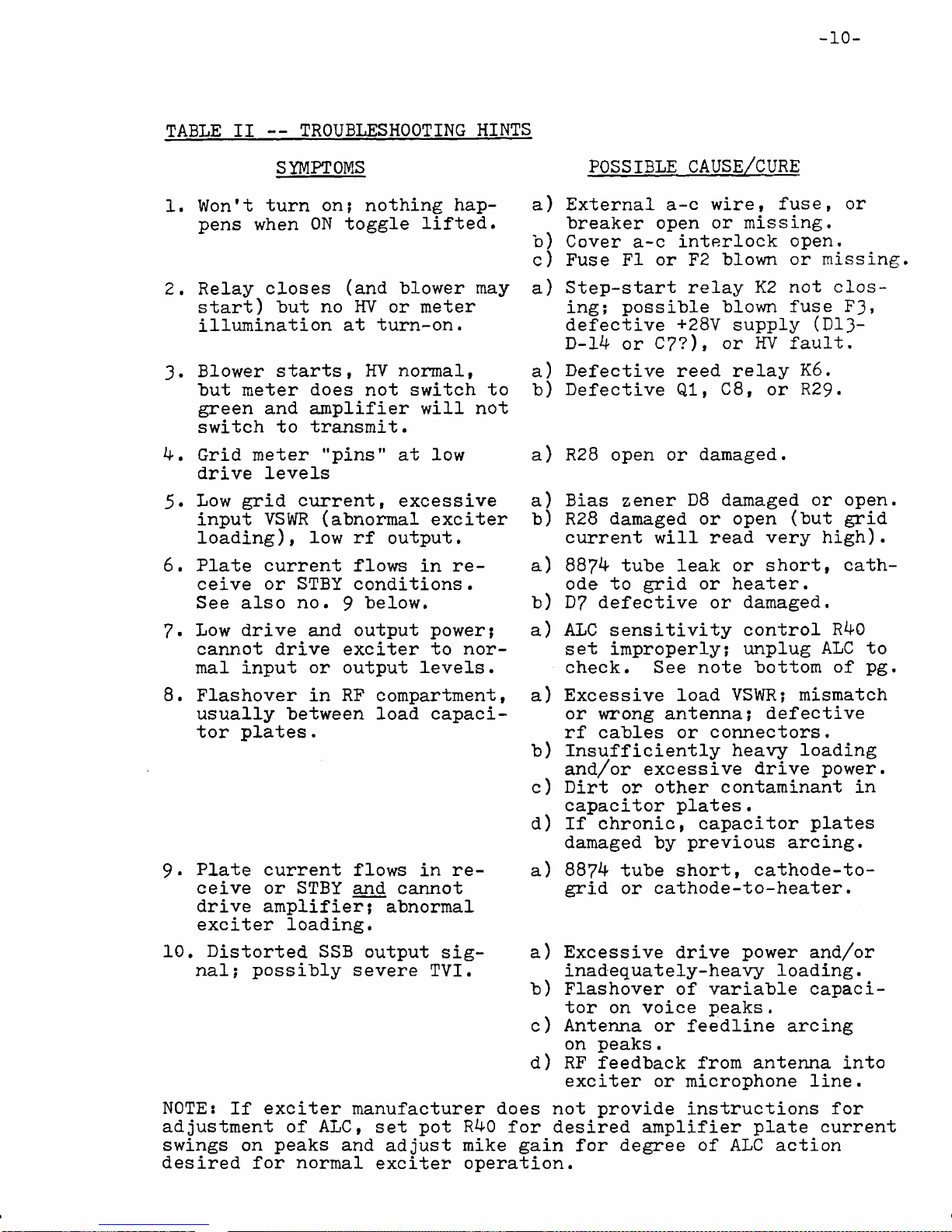
TABLE II -- TROUBLESHOOTING HINTS
SYMPTOMS
1. Won't turn on; nothing hap
p ns wh n ON toggl lift d.
2. R lay clos s (and blow r may
start) but no HV or m t r
illumination at turn-on.
3. Blow r starts, HV normal,
but m t r do s not switch to
gr n and amplifi r will not
switch to transmit.
4. Grid m t r "pins
driv l v ls
5.
6.
7.
8.
9-
nat low
Low grid curr nt, xc ssiv
input VSWR (abnormal xcit r
loading), low rf output.
Plat curr nt flows in r
c iv or STBY conditions.
S also no. 9 b low.
Low driv and output pow r;
cannot driv xcit r to nor
mal input or output l v ls.
Flashov r in RF compartm nt,
usually b tw n load capaci
tor plat s.
Plat curr nt flows in r
c iv or STBY and cannot
driv amplifi r; abnormal
xcit r loading.
a)
D
C
a
b
a
b
a
a
10. Distort d SSB output sig
nal; possibly s v r TVI. Exc ssiv driv pow r and/or
inad quat ly-h avy loading.
Flashov r of variabl capaci
tor on voic p aks.
Ant nna or f dlin arcing
on p aks.
RF f dback from ant nna into
xcit r or microphon lin .
NOTE: If xcit r manufactur r do s not provid instructions for
adjustm nt of ALC, s t pot R40 for d sir d amplifi r plat curr nt
swings on p aks and adjust mik gain for d gr of ALC action
d sir d for normal xcit r op ration.
POSSIBLE CAUSE/CURE
Ext rnal a-c wir , fus , or
br ak r op n or missing.
Cov r a-c int rlock op n.
Fus FI or F2 blown or missing
St p-start r lay K2 not clos
ing; possibl blown fus F3»
d f ctiv +28V supply (D13-
D-14 or C7?)» or HV fault.
D f ctiv r d r lay K6.
D f ctiv Q1, C8, or R29.
R28 op n or damag d.
Bias z n r D8 damag d or op n.
R28 damag d or op n (but grid
curr nt will r ad v ry high).
8874 tub l ak or short, cath
od to grid or h at r.
D7 d f ctiv or damag d.
ALC s nsitivity control R40
s t improp rly; unplug ALC to
ch ck. S not bottom of pg.
Exc ssiv load VSWR; mismatch
or wrong ant nna; d f ctiv
rf cabl s or conn ctors.
Insuffici ntly h avy loading
and/or xc ssiv driv pow r.
Dirt or oth r contaminant in
capacitor plat s.
If chronic, capacitor plat s
damag d by pr vious arcing.
8874 tub short, cathod -to-
grid or cathod -to-h at r.
I

SECTION 4
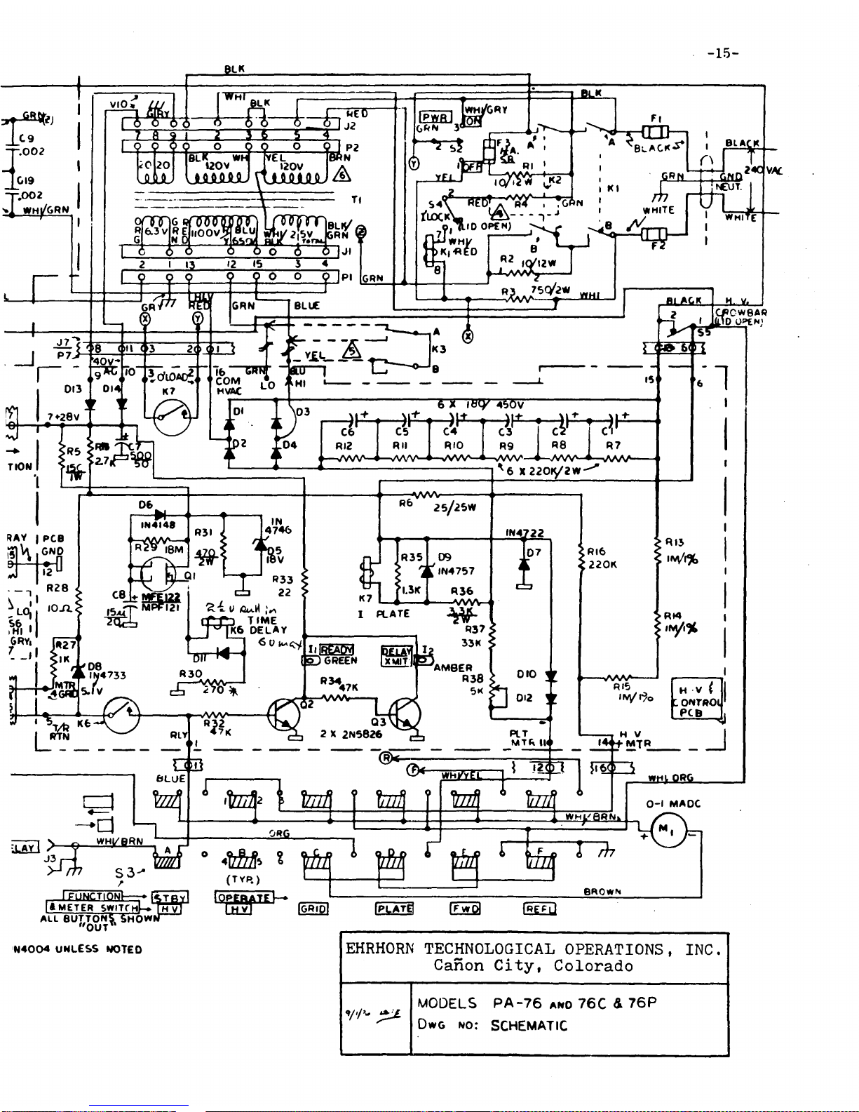
RF Amplifi r S ction: Tub s VI and V2 (and V3 in mod ls 76P and
76C) ar parall l-conn ct d in a ground d grid configuration.
+28 volts of cathod bias is appli d via R7 and L7 to cut off
plat curr nt during non-transmit p riods; bias is r duc d to an
op rating l v l of 5«1 volts wh n th ant nna r lay is actuat d.
RF xcitation is appli d to th cathod s via a broadband, toroidal
f rrit matching transform r, T2. R sistor n tworks R17 and (in
standard mod l 76 only) R22 stablish a nominal driv pow r r
quir m nt of 100 watts PEP and h lp provid a 50 ohm input imp d
anc •
Th plat output circuit is a full pi-L n twork consisting of
C16, L1-L2-L3, C17> and L4. Th pi-L provid s harmonic suppr ssion
substantially b tt r than a simpl pi n twork, as w ll as som what
b tt r ffici ncy in this application.
An rf dir ctional wattm t r, consisting of L9 and associat d com
pon nts, s ns s forward and r fl ct d pow r in th rf output lin
for display on th pan l m t r wh n s l ct d by push-buttons FWD
and REFL, r sp ctiv ly.
Excitation voltag is d t ct d and filt r d by ALC r ctifi r C23-
C24, D15, and associat d compon nts. Th driv l v l at which
n gativ -going ALC is g n rat d (i. ., th thr shold l v l) is
s t by r ar-pan l pot ntiom t r R40 which back-bias s D15.
R lay K4 switch s th ant nna straight through to th xcit r
wh n th amplifi r is OFF or in STBY or r c iv conditions, p r
mitting normal transc iv op ration. K4 switch s th ALPHA 76
into th transmit configuration wh n an xt rnal short is plac d
across RELAY control jack, J3-
Pow r Supply: Transform r T1 is a 1.5 KVA continuous-s rvic unit
(2.4 KVA Hip rsilSXcor in PA-76C only) which suppli s all r
quir d a-c op rating voltag s for th amplifi r.
High voltag d-c for th tub anod s is r ctifi d by a full-wav
bridg , D1-D4, and filt r d by a 30 mfd., 2.7 KV capacitor con
sisting of C1-C6 in s ri s. Th s comput r-grad l ctrolytic
capacitors ar factory capacitanc -match d to insur uniform a-c
rippl voltag distribution and long s rvic lif .
High voltag may b r duc d from th normal SSB valu of 2.2-2.4
KV to approximat ly 1.4-1.6 KV by taking th HV r ctifi r input
from an alt rnat transform r tap. A high voltag tap-chang
r lay, K3 (standard in PA-76C, optional in oth r mod ls), control
l d by Hl/LO toggl switch S6, p rmits making this s l ction from
th front pan l. In units without th HV r lay, th s l ction is
mad with quick-conn ct lugs on th HV circuit board.
Cov r int rlock switch S4 pr v nts actuation of main pow r r lay
K1 unl ss th top cov r is s cur d in plac . Saf ty "crowbar"
S5 plac s a low-r sistanc short across th HV supply (and dis
charg s th filt r capacitors) wh n v r th cov r is op n.
THEORY OF OPERATION
12
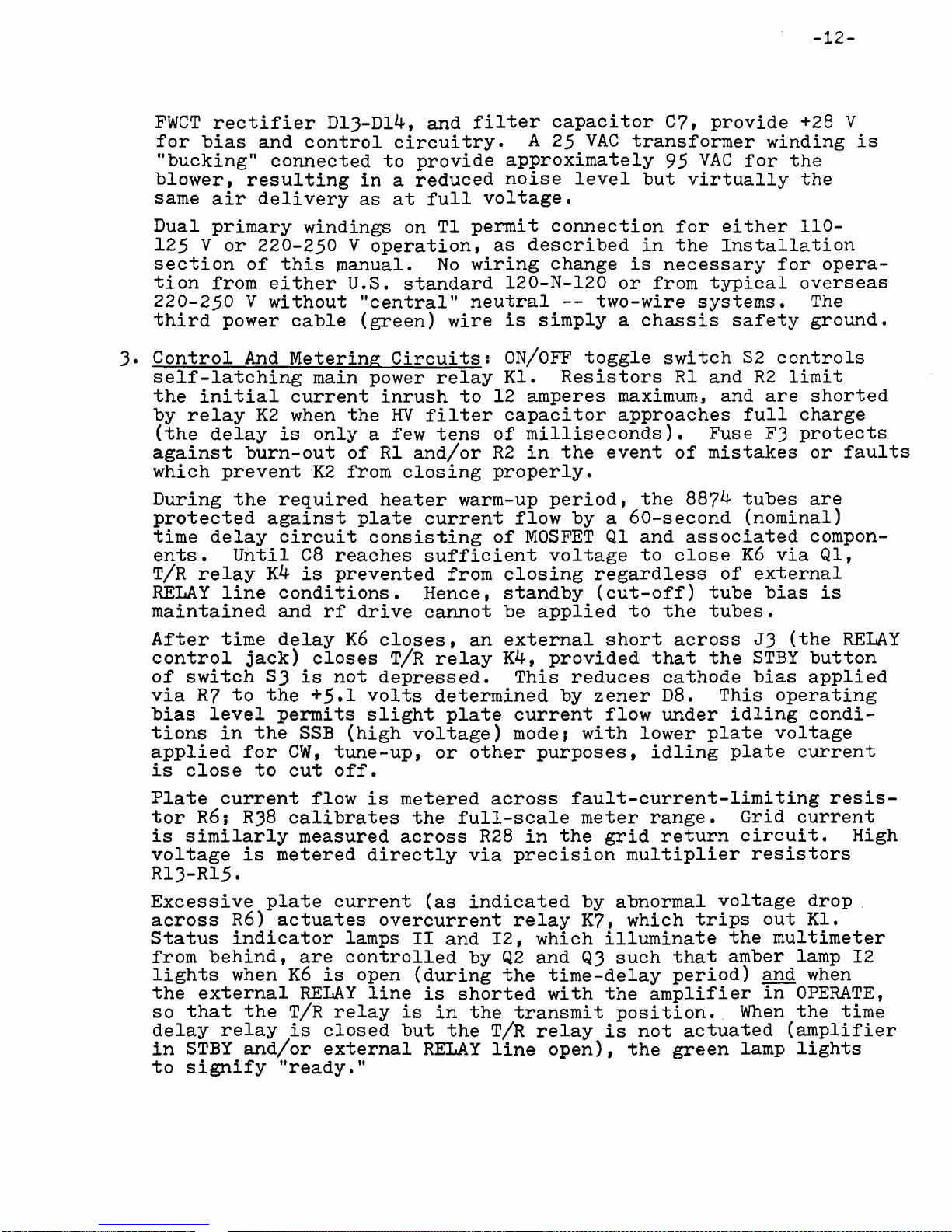
FWCT r ctifi r D13-D14, and filt r capacitor C7, provid +28 V
for bias and control circuitry. A 25 VAC transform r winding is
"bucking” conn ct d to provid approximat ly 95 VAC for th
blow r, r sulting in a r duc d nois l v l but virtually th
sam air d liv ry as at full voltag .
Dual primary windings on T1 p rmit conn ction for ith r 110-
125 V or 220-250 V op ration, as d scrib d in th Installation
s ction of this manual. No wiring chang is n c ssary for op ra
tion from ith r U.S. standard 120-N-120 or from typical ov rs as
220-250 V without "c ntral" n utral -- two-wir syst ms. Th
third pow r cabl (gr n) wir is simply a chassis saf ty ground.
3. Control And M t ring Circuits 1 ON/OFF toggl switch S2 controls
s lf-latching main pow r r lay Kl. R sistors R1 and R2 limit
th initial curr nt inrush to 12 amp r s maximum, and ar short d
by r lay K2 wh n th HV filt r capacitor approach s full charg
(th d lay is only a f w t ns of millis conds). Fus F3 prot cts
against burn-out of R1 and/or R2 in th v nt of mistak s or faults
which pr v nt K2 from closing prop rly.
During th r quir d h at r warm-up p riod, th 8874 tub s ar
prot ct d against plat curr nt flow by a 60-s cond (nominal)
tim d lay circuit consisting of MOSFET Q1 and associat d compon
nts. Until C8 r ach s suffici nt voltag to clos K6 via Ql,
T/R r lay K4 is pr v nt d from closing r gardl ss of xt rnal
RELAY lin conditions. H nc , standby (cut-off) tub bias is
maintain d and rf driv cannot b appli d to th tub s.
Aft r tim d lay K6 clos s, an xt rnal short across J3 (th RELAY
control jack) clos s T/R r lay K4, provid d that th STBY button
of switch S3 is not d pr ss d. This r duc s cathod bias appli d
via R7 to th +5*1 volts d t rmin d by z n r D8. This op rating
bias l v l p rmits slight plat curr nt flow und r idling condi
tions in th SSB (high voltag ) mod ? with low r plat voltag
appli d for CW, tun -up, or oth r purpos s, idling plat curr nt
is clos to cut off.
Plat curr nt flow is m t r d across fault-curr nt-limiting r sis
tor R6; R38 calibrat s th full-scal m t r rang . Grid curr nt
is similarly m asur d across R28 in th grid r turn circuit. High
voltag is m t r d dir ctly via pr cision multipli r r sistors
R13-R15.
Exc ssiv plat curr nt (as indicat d by abnormal voltag drop
across R6) actuat s ov rcurr nt r lay K7, which trips out Kl,
Status indicator lamps II and 12, which illuminat th multim t r
from b hind, ar controll d by Q2 and Q3 such that amb r lamp 12
lights wh n K6 is op n (during th tim -d lay p riod) and wh n
th xt rnal RELAY lin is short d with th amplifi r in OPERATE,
so that th T/R r lay is in th transmit position. Wh n th tim
d lay r lay is clos d but th T/R r lay is not actuat d (amplifi r
in STBY and/or xt rnal RELAY lin op n), th gr n lamp lights
to signify "r ady."

SECTION S — ILLUSTRATIONS
FIGURE 1 - Transform r Installation or R moval

-1k-
FIC-URE 3 - Top Vi w Showing Ma.ior Compon nt Locations
1K1-K2-K3 UNDERNEATH

NOTES:
A R22-5 EACH470/2w:FA-?fc ONLf
A PA-76CJP0NL (V3CKTY)
SOME UHITS QIFFE« S u M l*
,^ \ ¿*/i2W EXCEPT SOME 3»02*
WITH 3.3K PARALLEL, SHORTEO
FOR 120V ©M_Y
A
A
OPTIONAL MV RELAY (K3>
XFMR LEAO .COLORS APPLY TO STO
PA-76 XFMR ONLY; HIPERSIL XFMR
WIRE COLORS VARY
— JJ jjE
l*MCTEt
ALL eUTl
"<
9. ALL O's IN4004 UNLEi
7. ALL CAPACITORS IKV UNLESS NOTED
fi. ALL RESISTORS 5 © lO% /IW UNLESS NOTEO
I * meter switThI-» m V
ALL BUTTONS, SHOV*
OUT
N4004 UNLESS NOTED EHRHORN TECHNOLOGICAL OPERATIONS, INC.
Can n City, C l rad
MODELS PA-76 ano 76C & 76P
Dwg n o : SCHEMATIC
-16-
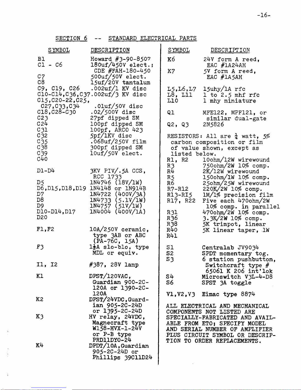
SECTION 6 STANDARD ELECTRICAL PARTS
SYMBOL DESCRIPTION
B1
Cl - C6
07
C8
09f 019t
C10-C14,
015,020-
C27,C33
C18,C28-
C23
02k
C31
C32
O35
038
039
C40
D1-D4
Howard #3-90-8507
180uf/450V l ct.;
CDE #FAH-l80-450
500uf/50V l ct.
15uf/20V tantalum
C26 .002uf/l KV disc
C36,C37-002uf/3 KV disc
22,02^t
,C34 ,01uf/50V disc
C30 .02/500V disc
27pf dipp d SM
lOOpf dipp d SM
lOOpf, ARCO 423
5pf/lKV disc
.068uf/250V film
300pf dipp d SM
10uf/50V l ct.
D5
D6,D15 »D18,D19
D7
D8
D9
D10-D14,D17
D20
F1,F2
3KV PIV/.5A CCS,
RCC 1733
IN4746 (18V/1W)
1N4148 or 1N914B
1N4722 (400V/3A)
1N4733 (5-1V/1W)
1N4757 (5IV/IW)
1N4004 (400V/1A)
F3
II, 12
K1
K2
K3
K4
IOA/25OV c ramic,
typ 3AB or ABC
(PA-76C, 15A)
1¿A slo-blo, typ
MDL or quiv.
#387» 28V lamp
DPST/12OVAC,
Guardian 900-2C-
12OA or I390-2C-
12 OA
DPST/ 24VDC, Guard
ian 905-2C-24D
or 1395-2C-24D
HV r lay, 24VDC,
Magn craft typ
W158-HVX-1-2ÍV
or P-B typ
PRD11DY0-24
DPDT/lOA,Guardian
905-2C-24D or
Phillips 39C11D24
SYMBOL
K6
K7
L5,L6,L7
L8, Lll
L10
Q1
Q2, Q3
24V form A r d,
EAC #1A24AH
5V form A r d,
EAC #1A5AH
15uhy/lA rfc
1 to 2.5 mhf rfc
1 mhy miniatur
MFE122, MPF121, or
similar dual-gat
2N5826
DESCRIPTION
RESISTORS: All ar \ watt, 5$
carbon composition or film
of valu shown, xc pt as
list d b low.
RI, R2
R3
R4
R5
R6
R7-R12
RI3-RI5
RI7, R22
R3I
R36
R38
R40
R4l
51
52
53
10ohm/l2W wir wound
75°ohm/2W 10$ comp.
2K/12W wir wound
150ohm/lW 10$ comp.
25ohm/25W wir wound
220K/2W 10# comp.
lM/l# pr cision film
Fiv ach 470ohm/2W
10# comp, in parall l
470ohm/2W 10# comp.
3.3K/2W 10# comp.
5K trimpot, lin ar
5K lin ar tap r, 1W
S4
S6
C ntralab JV9034
SPDT mom ntary tog.
6 station pushbutton,
Switchcraft typ #
65061 K 206 int'lok
Microswitch V3L-4-D8
SPST 3A toggl
VI,V2,V3 Eimac typ 8874
ALL ELECTRICAL AND MECHANICAL
COMPONENTS NOT LISTED ARE
SPECIAIiY-FABRICATED AND AVAIL
ABLE FROM ETO; SPECIFY MODEL
AND SERIAL NUMBER OF AMPLIFIER
PLUS CIRCUIT SYMBOL OR DESCRIP
TION TO ORDER REPLACEMENTS.

ETO/"ALPHA" PRODUCTS WARRANTY
EHRHORN TECHNOLOGICAL OPERATIONS, INC.(ETO) WARRANTS AS FOLLOWS
EACH NEW ELECTRONIC PRODUCT OF ITS MANUFACTURE:
(1) Workmanship and all compon nts xc pt rf pow r tub s ar
guarant d for EIGHTEEN MONTHS (VOMAX only, tw lv months)
from dat of original purchas if us d xclusiv ly in
lic ns d amat ur radio s rvic , and for nin ty days if
us d in non-amat ur s rvic .
(2) Pow r tub s ar warrant d by th ir manufactur r; ETO will
assist own rs in s curing warranty s rvic if r qu st d.
(3) Warranty do s not apply to r pair of damag r sulting from
improp r maint nanc or r pair, misus , n gl ct, abus , or
improp r installation, nor to units not op rat d in accord
anc with sp cifications and instructions furnish d by ETO,
nor to units r pair d or alt r d by p rsons not authoriz d
by ETO, nor in cas s wh r th s rial numb r has b n r
mov d, alt r d, or d fac d.
(4) If a malfunction is susp ct d, b for att mpting r pairs or
r turning quipm nt to ETO for s rvic th own r shall con
tact s lling d al r or factory s rvic d partm nt, providing
mod l and s rial numb rs plus d tails of quipm nt hook-up,
acc ssory quipm nt us d, op rating conditions, and abnor
maliti s obs rv d. ETO will furnish a n w part in xchang
for any cov r d d f ctiv part or, if it is d t rmin d that
factory s rvic is r quir d, will authoriz r turn to factory.
Equipm nt authoriz d for r turn shall b shipp d fully pr paid
and insur d via Unit d Parc l or air fr ight (to Colorado
Springs airport only), using only FACTORY APPROVED PACKING;
REMOVE POWER TRANSFORMER BEFORE SHIPPING ANY UNIT WHICH WAS
ORIGINALLY SHIPPED FROM THE FACTORY WITH TRANSFORMER REMOVED!
(5) In ord r to r c iv warranty s rvic , own r must hav r turn d
a compl t d warranty r gistration form to ETO within 15 days
of original purchas , or must provid proof of purchas dat
wh n r qu sting s rvic . Warranty will b transf rr d to sub
s qu nt own r provid d h notifi s ETO in writing of his nam ,
addr ss, dat of purchas , and th quipm nt mod l and s rial.
(6) No p rson is authoriz d to assum for ETO any liability,
oth r than as s t forth in this warranty, in conn ction with
our products. ETO r s rv s th right to chang its products
as it d ms d sirabl , without obligating its lf to mak
such chang s availabl for pr viously manufactur d products.
(UNDER PROVISIONS OF THE FEDERAL MAGNUSON-MOSS WARRANTY ACT,
THIS WARRANTY POLICY IS CLASSIFIED AS A LIMITED WARRANTY.)
EHRHORN TECHNOLOGICAL OPERATIONS, INC.
Ehihom Technological Operations, Inc. .
4975 No th 30th St eet W 7 7
Colo ado Sp ings, CO 80919
Table of contents
Other EHRHORN Amplifier manuals


