EHRHORN ALPHA 77Sx User manual

PRICE: $10.00
OPERATING AND TECHNICAL MANUAL
HIGH FREQUENCY LINEAR POWER AMPLIFIERS
ALPHA 77Dx an ALPHA 77Sx
EHRHORN TECHNOLOGICAL OPERATIONS, INC.
JANUARY 1990

IMPORTANT
SERVICE ASSISTANCE
To help you secure technical assistance without waste long istance calls, ETO
has establishe a special SERVICE telephone line WHICH WILL BE ANSWERED
ONLY WHEN A QUALIFIED SERVICE TECHNICIAN IS AVAILABLE TO HELP
YOU IMMEDIATELY.
The special service number is (719) 599-3861. If your call to this number is NOT
answere it in icates that no qualifie technician is free to talk with you at the
moment. Please wait a few minutes an try again. NOTE ALSO that business
hours are 8:30 A.M. to 4:30 P.M. MOUNTAIN TIME Mon ay through Thurs ay.
If your call oes NOT relate to service or other technical matters, our business
office staff will be happy to help you at the number shown on the rear cover of
this manual.
TEN METER OPERATION OF YOUR ALPHA
FCC rules permit an appropriately license amateur to mo ify his own amplifier
for operation on 28-29.7 MHz. We strongly recommen that you contact our
service epartment before attempting any mo ification. (If you enclose your
request an a photocopy of your vali amateur ra io license with the warranty
registration car for your new amplifier, appropriate information will be sent
without charge.)
THE EXPECTED NEW 10, 18 an 24 MHz AMATEUR BANDS
If an when FCC permits amateur use of these ban s with linear amplifiers,
your ALPHA will be capable of 10 an 18 MHz operation with only slight mo i
fication. In the somewhat unlikely event that high power operation is eventually
permitte on 24 MHz, ETO may make available information to permit safe operation
of your ALPHA on that ban . ANY ATTEMPT TO OPERATE YOUR ALPHA IN
THE VICINITY OF 24 MHZ WITHOUT APPROPRIATE MODIFICATION MAY
CAUSE SERIOUS DAMAGE.
1/90

TABLE OF CONTENTS
SECTION 1 - GENERAL DESCRIPTION & SPECIFICATIONS
.........
1
SECTION 2 - INSTALLATION
...............................
2
Electrical Installati n (AC P wer Wiring) . . . 2
RF and C ntr l C nnecti ns
..................
5
SECTION 3 - OPERATION
.................................
8
C ntr l P siti ns .......................... 8
Tune-up Pr cedure . .
......................
9
Final Operati nal Adjustments «Sc M nit ring . . 11
Operating N t e s
.........
................
12
Tr ublesh ting Hints .
.
..................
14
SECTION 4 - THEORY OF OPERATION
......................
16
SECTION 5 - ILLUSTRATIONS
...........................
21
Fr nt Panel; Rear Panel
.
..................
21
Fr nt Sub-panel; Back Side f Fr nt Panel . . 22
RF Secti n, T p and Side, C vers Rem ved . . 23
P wer Supply Secti n, Side and Oblique .... 24
Tube Deck, Underside; Circuit B ard CB-2 . „ . 25
Circuit B ard CB-3; Wattmeter „ . . . . . . . 26
Schematic, RF Secti n & Tube D e c k
.........
2?
Schematic, P wer Supply & Main Chassis .... 28
Schematic, Fr nt Panel
....................
29
Schematic, Circuit B ard CB-2
.............
3°
Schematic, QSK Circuit B ard CB-3
.........
31
SECTION 6 - STANDARD ELECTRICAL PARTS L I S T
.............
32
ET0/"ALPHA" PRODUCT WARRANTY
...........
Outside Back C ver
EHRHORN TECHNOLOGICAL OPERATIONS, INC.
4975 NORTH 30TH STREET
COLORADO SPRINGS, COLORADO 80919 U.S.A.
REV. 1/90 @ U.S.A.

I
SECTION 1
GENERAL DESCRIPTION
The ALPHA 77Dx (type accepted m del PA-77DF and g vernment/exp rt
m del PA-77Dx)* is a high p wer HF linear amplifier f excepti nal
quality, ruggedness, and s phisticated design. It is much smaller
than ther amplifiers f c mparable capability, yet pr vides great
er perati nal versatility, c ler perati n, and a l wer ac usti
cal n ise level than much larger and heavier units.
Unique design features f the ALPHA 7?Dx include ETO's exclusive
full-cabinet ducted air c ling system, built-in CW break-in key
ing system, frequency c verage d wn t 1.8 MHz, and a highly effi
cient cust m p wer transf rmer using a tape-w und c re f grain-
riented silic n steel. High efficiency f perati n is maintained
acr ss the tuning range by a c mbinati n f vacuum variable utput
tuning capacit r and ETO's expertly designed mixture f silver plat
ed, heavy c pper tubing c ils and multi-insulated, t r idal induct rs.
SPECIFICATIONS (M dels PA-77DF and PA-77Dx)
Frequency C veragei 1.8-2.0 and 3-24 MHz (*24-30 MHz, PA-77Dx nly).
Plate P wer Input» PA-77DF 2.5 KW PEP/SSB, 1 KW average d-c, all
m des, n time limit» PA-77Dx 3*5 KW PEP, 2 KW d-c average, NTL.
Plate Efficiency» Typically 60# r better.
Drive P weri N minal 60-70 watts carrier, 100-150 watts PEP.
Input & Output Impedances» N minal 50 hms unbalanced * VSWR under 2*1.
Dist rti n: Third rder IM m re than 36 dB bel w 1.5 KW PEP utput.
Harm nics» M re than 50 dB bel w mean fundamental frequency utput.
Tube C mplement» One Eimac 8877 ceramic tri de, gr unded grid.
C ling» Full-cabinet ducted f rced airj ball bearing centrif. bl wer.
ALC» Adjustable-thresh ld, grid-current-derived, negative g ing.
Pr tecti n» Primary and step-start fuses, plate vercurrent s len id,
a-c line and high v ltage c ver interl cks.
Primary P wer» 220-250V with gr unded center neutral, 50-60 Hz, stan
dard. Simple re-c nnecti n acc mm dates 110-125V, 120-208V, r
220-250V with ut center neutral. 240V supply with 20A fuses r
sl w breakers is adequate f r all-m de perati n at full ratings.
Size & Weight» ll"h. x 19"w. x 22"d. (28 x 48 x 56 cm). Net weight
95 lb. (43 kg), shipping weight 125 (57 kg) in tw cart ns.
VARIATIONS FOR GOVERNMENT/EXPORT-ONLY MODEL ALPHA 77Sx (PA-77Sx)t
Same as ALPHA 77Dx (PA-77Dx) ab ve except tw 8877 tubes permit
greater PEP input and utput p wer. Appr ximately 175 watts
drive f r maximum utput. Net wt. 105 lb. (48 kg), shipping
weight 130 lb. (59 kg).
*N0TE: Only FCC type-accepted model PA-77DF may legally be sold ithin the U.S,
except to government customers. PA-77Dx £ PA-77Sx available only for
export and government customers.
-1-
SECTION 2
TNSTALLATT ON
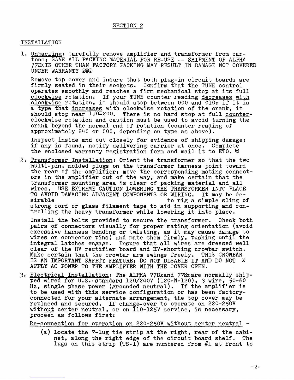
1. Unpacking: Carefully rem ve amplifier and transf rmer fr m car
t ns; SAVE ALL PACKING MATERIAL FOR RE-USE — SHIPMENT OF ALPHA
77DXIN OTHER THAN FACTORY PACKING MAY RESULT IN DAMAGE NOT COVERED
UNDER WARRANTY ©£©
Rem ve t p c ver and insure that b th plug-in circuit h ards are
firmly seated in their s ckets. C nfirm that the TUNE c ntr l
perates sm thly and reaches a firm mechanical st p at its full
cl ckwise r tati n. If y ur TUNE c unter reading decreases with
cl ckwise r tati n, it sh uld st p "between 000 and 010; if it is
a type that increases with cl ckwise r tati n f the crank, it
sh uld st p near 190-200. There is n hard st p at full c unter
cl ckwise r tati n and cauti n must be used t av id turning the
crank bey nd the n rmal end f r tati n (c unter reading f
appr ximately 240 r 000, depending n type as ab ve).
Inspect inside and ut cl sely f r evidence f shipping damage;
if any is f und, n tify delivering carrier at nce. C mplete
the encl sed warranty registrati n f rm and mail it t ET0. ©
2. Transf rmer Installati n: Orient the transf rmer s that the tw
multi-pin, m lded plugs n the transf rmer harness p int t ward
the rear f the amplifier; m ve the c rresp nding mating c nnect
rs in the amplifier ut f the way, and make certain that the
transf rmer m unting area is clear f packing material and all
wires. USE EXTREME CAUTION LOWERING THE TRANSFORMER INTO PLACE
TO AVOID DAMAGING ADJACENT COMPONENTS OR WIRING. It may be de
sirable t rig a simple sling f
str ng c rd r glass filament tape t aid in supp rting and c n
tr lling the heavy transf rmer while l wering it int place.
Install the b lts pr vided t secure the transf rmer. Check b th
pairs f c nnect rs visually f r pr per mating rientati n (av id
excessive harness bending r twisting, as it may cause damage t
wires r c nnect r pins) and mate them firmly, pushing until the
integral latches engage. Insure that all wires are dressed well
clear f the HV rectifier b ard and HV-sh rting cr wbar switch.
Make certain that the cr wbar arm swings freely. THIS CROWBAR
IS AN IMPORTANT SAFETY FEATURE; DO NOT DISABLE IT AND DO NOT ©
APPLY AC POWER TO THE AMPLIFIER WITH THE COVER OPEN.
3» Electrical Installati n: The ALPHA 77Dxand 77Sxare n rmally ship
ped wired f r U.S.-standard 120/240V (120-N-120), 3 wire, 50-60
Hz, single phase p wer (gr unded neutral). If the amplifier is
t be used with this service c nfigurati n r has been fact ry-
c nnected f r y ur alternate arrangement, the t p c ver may be
replaced and secured. If change- ver t perate n 220-250V
with ut center neutral, r n 110-125V service, is necessary,
pr ceed as f ll ws first*
Re-c nnecti n f r perati n n 220-250V with ut center neutral -
(a) L cate the 7-lug tie strip at the right, rear f the cabi
net, al ng the right edge f the circuit b ard shelf. The
lugs n this strip (TS-1) are numbered fr m #1 at fr nt t
-2

#7 at the back. The standard wiring t TS-1 (f r 120/240V
with center neutral) is as f ll ws* (See Fig. 1, page 4)
LUG 1 — Gr und (m unting f t f r terminal strip)
LUG 2 — White/black wire
LUG 3 — White wire
LUG 4 — Green, red, white/green & white/ range wires *
LUG 5 — White/vi let wire and ne bl wer wire (gray r blk)
LUG 6 — Black wire *
LUG 7 — Gr und f t; gray wires
* A tubular capacit r is c nnected als fr m #4 t #6.
(b) Rem ve the white/green wire nly fr m LUG 4 and c n
nect it instead t LUG 2. (See Fig. 2, page 4)
(c) Add a new resist r (700 hms, 8 t 12 watt) between
LUG 3 and LUG 4; keep it clear f all wires and parts.
(d) Rem ve the c ver fr m the 6 pin c nnect r n the AC
p wer cable; rem ve the wire jumper c nnected between
pins 10 and 11. Pin 11 is then blank and unused; nly
the green p wer cable wire (chassis) g es t pin 10.
(e) Replace p wer c nnect r c ver and amplifier t p c ver.
(f) The 240V service wires c nnect t black and white wires
f the cable; green g es t gr und nly.
Re-c nnecti n f r perati n n 110-125V service - All required
re-c nnecti ns are made inside the p wer cable c nnect r itself;
rem ve its c ver. (See Figure 5» page 4)
*
(a) Rem ve the existing jumper wire between pins 7 and 9«
Rem ve als the jumper wire between pins 10 and 11.
(b) Add a new jumper wire fr m pin 7 thr ugh pin 12 and n t
pin 11. Add an ther jumper wire fr m pin 8 t pin 9.
Replace cap n c nnect r.
(c) The 120V AC service wires c nnect t the black (fr m pins
8 & 9) and white (fr m pins 7i 11» & 12) p wer cable wires.
The green wire (chassis) c nnects t p wer system gr und.
F r inf rmati n n use with any ther type f primary mains c n
figurati n, c ntact ET0 fact ry.
P wer Cable C nnecti ns - The green wire in the main amplifier
AC p wer cable is c nnected t chassis and must always (and nly!)
be wired t the AC mains gr und ( r center neutral with U.S. stan
dard 120-N-120V system). The black and white wires are inter
changeable and c nnect t the tw "h t" wires f the service.
Service wiring sh uld be at least #12 AWG c pper, pr tected by
fuses r breaker rated at 20 t 30 amperes (#10 AWG, 30 ampere
fuses r breaker f r PA-77SjJ .
4. Physical L cati n: The amplifier must be p siti ned h riz ntally,
and s that the intake f c l air and exhaust f h t air is n t
impeded in any way, and s that h t exhaust air cann t signifi
cantly recirculate back int the c l air intake area. A minimum
f six inches clearance sh uld be all wed behind the amplifier,
with pen access t surr unding air unless special ducting pr
visi ns are pr vided.
-3
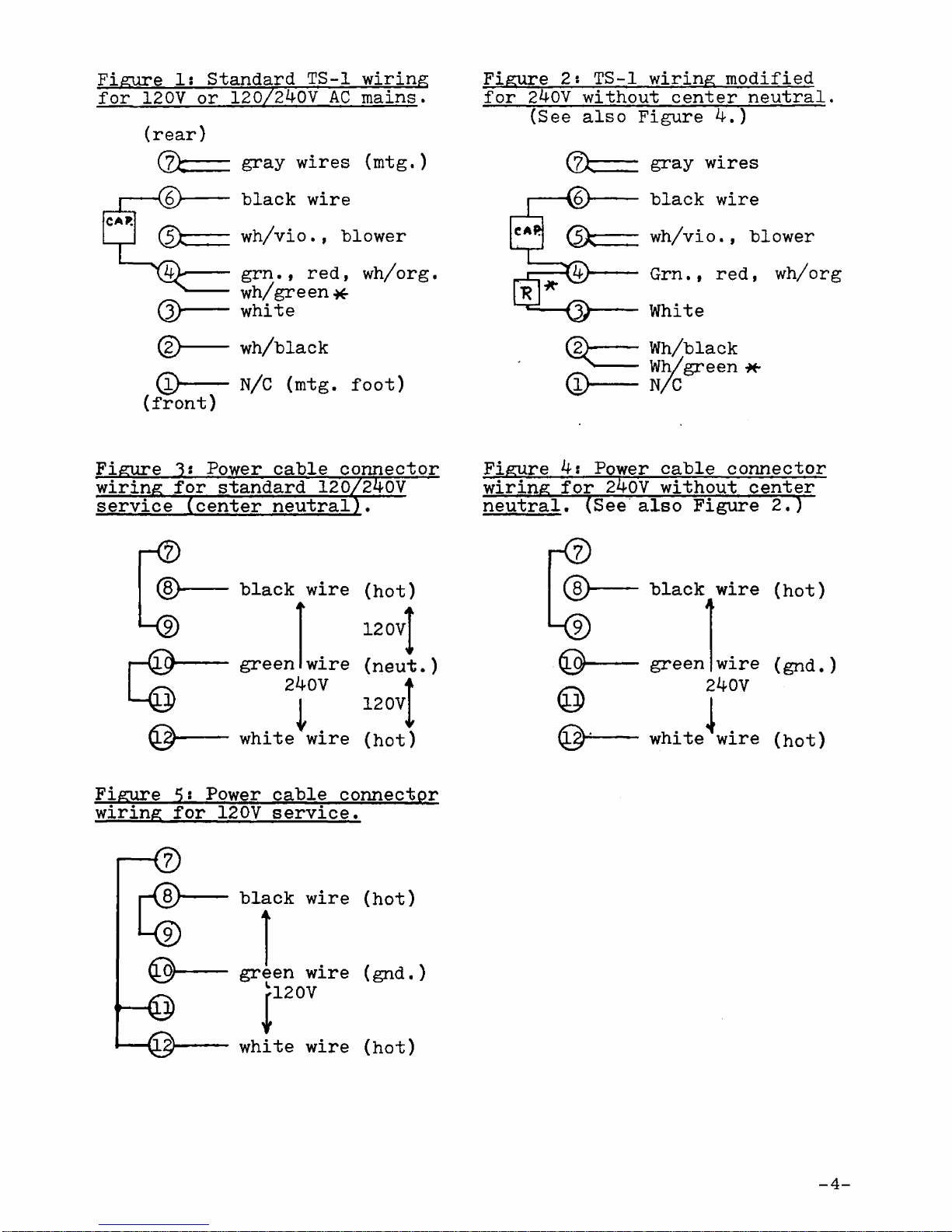
Figure 1: Standard TS-1 wiring
f r 120V r 120/240V AC mains.
(rear)
d>
©—
(fr nt)
gray wires (mtg.)
black wire
wh/vi ., bl wer
grn., red,
wh/green*
white
wh/black
wh/ rg.
N/C (mtg. f t)
Figure 2: TS-1 wiring m dified
f r 240V with ut center neutral.
(See als Figure 4.)
(zfc
<k
© -
gray wires
black wire
w.
h/vi ., bl wer
Grn., red, wh/ rg
White
Wh/black
Wh/green *-
N/C
Figure 3? P wer cable c nnect r
wiring f r standard 120/240V
service (center neutral).
-<2>
d>
L ®
r © -
black wire
a
green wire
240V
(h t)
120vT
(neut
120 V
)
white wire (h t)
Figure 4: P wer cable c nnect r
wiring f r 240V with ut center
neutral" (See als Figure 2.)
- 0
d>
© -
black wire (h t)
A
green wire (gnd.)
240V
i
white wire (h t)
Figure 5: P wer cable c nnect r
wiring f r 120V service.
-d>
k D
© -
black wire (h t)
green wire (gnd.)
|!2°V
white wire (h t)
-4-
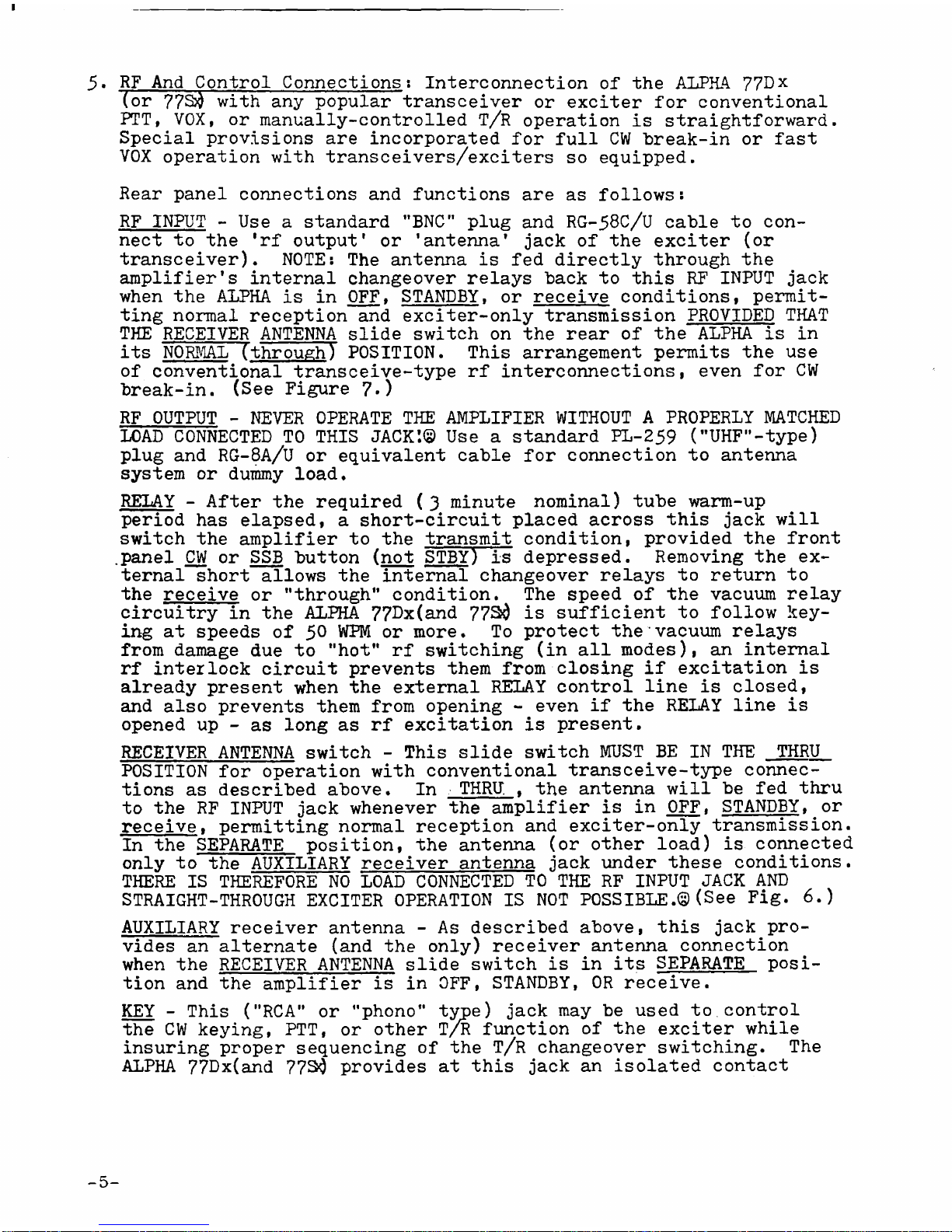
5. RF And C ntr l C nnecti ns: Interc nnecti n f the ALPHA 77Dx
( r 77S$ with any p pular transceiver r exciter f r c nventi nal
PTT, VOX, r manually-c ntr lled T/R perati n is straightf rward.
Special pr visi ns are inc rp rated f r full CW break-in r fast
VOX perati n with transceivers/exciters s equipped.
Rear panel c nnecti ns and functi ns are as f ll ws:
RF INPUT - Use a standard "BNC" plug and RG-58C/U cable t c n
nect t the 'rf utput' r 'antenna' jack f the exciter ( r
transceiver). NOTE: The antenna is fed directly thr ugh the
amplifier's internal change ver relays back t this RF INPUT jack
when the ALPHA is in OFF, STANDBY, r receive c nditi ns, permit
ting n rmal recepti n and exciter- nly transmissi n PROVIDED THAT
THE RECEIVER ANTENNA slide switch n the rear f the ALPHA is in
its NORMAL Tthr ugh) POSITION. This arrangement permits the use
f c nventi nal transceive-type rf interc nnecti ns, even f r CW
break-in. (See Figure 7-)
RF OUTPUT - NEVER OPERATE THE AMPLIFIER WITHOUT A PROPERLY MATCHED
LOAD CONNECTED TO THIS JACK'.© Use a standard PL-259 ("UHF"-type)
plug and RG-8A/U r equivalent cable f r c nnecti n t antenna
system r dummy l ad.
RELAY - After the required (3 minute n minal) tube warm-up
peri d has elapsed, a sh rt-circuit placed acr ss this jack will
switch the amplifier t the transmit c nditi n, pr vided the fr nt
.panel CW r SSB butt n (n t STBY) is depressed. Rem ving the ex
ternal sh rt all ws the internal change ver relays t return t
the receive r "thr ugh” c nditi n. The speed f the vacuum relay
circuitry in the ALPHA 77^x(and 77Si is sufficient t f ll w key
ing at speeds f 5° WPM r m re. T pr tect the vacuum relays
fr m damage due t "h t" rf switching (in all m des), an internal
rf interl ck circuit prevents them fr m cl sing if excitati n is
already present when the external RELAY c ntr l line is cl sed,
and als prevents them fr m pening - even if the RELAY line is
pened up - as l ng as rf excitati n is present.
RECEIVER ANTENNA switch - This slide switch MUST^ BE IN THE THRU
POSITION f r perati n with c nventi nal transceive-type c nnec
ti ns as described ab ve. In THRU, t the antenna will be fed thru
t the RF INPUT jack whenever the amplifier is in OFF, STANDBY, r
receive. permitting n rmal recepti n and exciter- nly transmissi n.
In the SEPARATE p siti n, the antenna ( r ther l ad) is c nnected
nly t the AUXILIARY receiver antenna jack under these c nditi ns.
THERE IS THEREFORE NO LOAD CONNECTED TO THE RF INPUT JACK AND
STRAIGHT-THROUGH EXCITER OPERATION IS NOT POSSIBLE.© (See Fig. 6.)
AUXILIARY receiver antenna - As described ab ve, this jack pr
vides an alternate (and the nly) receiver antenna c nnecti n
when the RECEIVER ANTENNA slide switch is in its SEPARATE p si
ti n and the amplifier is in OFF, STANDBY, OR receive.
KEY - This ("RCA" r "ph n " type) jack may be used t .c ntr l
the CW keying, PTT, r ther T/R functi n f the exciter while
insuring pr per sequencing f the T/R change ver switching. The
ALPHA 77Dx(and 77$0 pr vides at this jack an is lated c ntact
5-

cl sure which f ll ws the keying imp sed externally n the RELAY
jack,with ne restraint: the utput KEY line d es n t cl se until
the amplifier's internal change ver relay c ntacts have actually
cl sed. The KEY line pens immediately, h wever, when the input
line t the RELAY jack is pened. When the amplifier is in OFF r
STANDBY, the RELAY jack is c nnected thr ugh t the KEY jack.
High speed CW break-in r VOX is available with ut auxiliary T/R
switches and with ut danger f "h t switching" high p wer rf -- ©
PROVIDED THAT THE TRANSCEIVER OR TRANSMITTER-RECEIVER USED IS
ITSELF CAPABLE OF BREAK-IN KEYING — by patching the CW key ( r
VOX relay c ntacts) directly int the ALPHA'S RELAY jack, and
patching the amplifier's KEY jack utput back int the exciter
key jack ( r, f r VOX, int the line n rmally c ntr lled by the
VOX relay c ntacts). (See Figure 8.)
By using the amplifier's AUXILIARY receiver antenna jack t pr
vide the receiver's antenna input, full break-in CW perati n is
p ssible with many separate transmitter-receiver c mbinati ns
that d n t themselves inc rp rate adequate T/R antenna switching
f r break-in. BECAUSE THERE IS NO EXCITER LOAD CONNECTED UNLESS
THE ALPHA ?7Dx(77Si$ IS IN THE TRANSMIT CONDITION, IT IS ESSENTIAL
TO USE THE FULL BREAK-IN KEYING CONNECTIONS (Fig. 8) AND TO BE
CERTAIN THAT THE RECEIVER ANTENNA slide switch IS RETURNED TO
NORMAL BEFORE ATTEMPTING EXCITER-ONLY OPERATION. (See Fig. 6.)
ALC - ALC may be used with suitably-equipped exciter/transceivers
t help maintain excitati n at a desired maximum level. A nega
tive -g ing ALC c ntr l v ltage appears at the ALC jack when
amplifier grid current exceeds a preset value determined by adjust
ment f the ALC thresh ld trimmer p tenti meter (l cated near the
t p f the main plug-in circuit b ard, CB2, at the rear f the
p wer supply c mpartment).
This negative-g ing ALC is c mpatible with virtually all p pular
exciter/transceivers using vacuum tube p wer utput stages; s me
newer all-s lid-state transceivers (such as certain Atlas and
Ten-Tec m dels) utilize p sitive-g ing ALC, but als inc rp rate
their wn adjustable-thresh ld internal ALC which is suitable
f r excitati n c ntr l in lieu f amplifier-generated ALC.
In either event, it is necessary that the ALC thresh ld c ntr l
be set t pr vide the desired amplifier plate current meter swing
while the exciter mike gain c ntr l is simultane usly adjusted t
yield the degree f exciter ALC acti n specified by the exciter
manufacturer. The tw adjustments are s mewhat interacting, s
that several iterative readjustements may be necessary t achieve
desired results. EXCESSIVE MIKE GAIN OR ALC SENSITIVITY MAY
RESULT IN VERY LOW POWER OUTPUT, ALC "HANG-UP," AND/OR DISTORTION. ©
Figure 6: Simplified ALPHA 77Dy(77S^ Antenna Switching System
RCVR. A N T S M
-6-
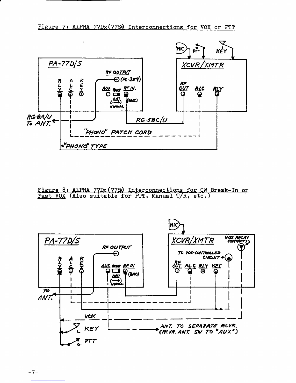
Figure 7» ALPHA 77Dx(77Sd Interconnections for VOX or PTT
R G rS A /U
75 A N T . R G -S 8C /U
|
___
<"PHOrJd' TY P E
x c v r /x m t r
*F
OUT
Q¿1C
I
I
+
¥
Figure 8»ALPHA 77Dx(77Sd Interc nnecti ns f r CW Break-In r
Fast VOX (Als suitable f r PTT, Manual T/R, etc.) ~
xcvr/x m t r
9
?
ALC RLY £Y T
9
ro vox-a*rmou£j>
ctficutr**
vox kszay
CONTACTS}
I
J
ANT. TO S£ P A X A T * ROVR.
(RCVX. A N T SV n *AUXm)
SECTION 3
1. C ntr l Functi ns:
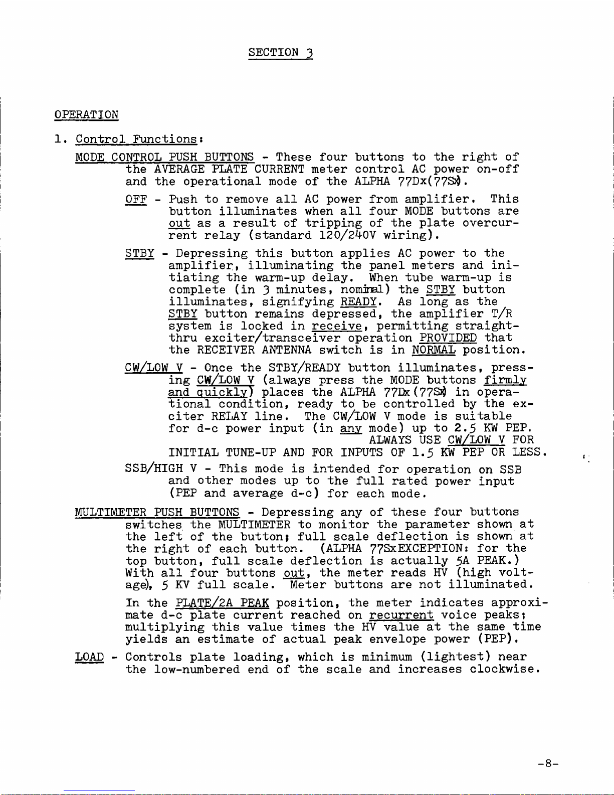
MODE CONTROL PUSH BUTTONS - These f ur butt ns t the right f
the AVERAGE PLATE CURRENT meter c ntr l AC p wer n- ff
and the perati nal m de f the ALPHA 77Dx(77S$.
OFF - Push t rem ve all AC p wer fr m amplifier. This
butt n illuminates when all f ur MODE butt ns are
ut as a result f tripping f the plate vercur
rent relay (standard 120/240V wiring).
STBY - Depressing this butt n applies AC p wer t the
amplifier» illuminating the panel meters and ini
tiating the warm-up delay. When tube warm-up is
c mplete (in 3 minutes, n minal) the STBY butt n
illuminates, signifying READY. As l ng as the
STBY butt n remains depressed, the amplifier T/R
system is l cked in receive, permitting straight-
thru exciter/transceiver perati n PROVIDED that
the RECEIVER ANTENNA switch is in NORMAL p siti n.
CW/LOW V - Once the STBY/READY butt n illuminates, press
ing CW/LOW V (always press the MODE butt ns firmly
and quickly) places the ALPHA 77Dx(77S$ in pera
ti nal c nditi n, ready t be c ntr lled by the ex
citer RELAY line. The CW/LOW V m de is suitable
f r d-c p wer input (in any m de) up t 2.5 KW PEP.
ALWAYS USE CW/LOW V FOR
INITIAL TUNE-UP AND FOR INPUTS OF 1.5 KW PEP OR LESS
SSB/HIGH V - This m de is intended f r perati n n SSB
and ther m des up t the full rated p wer input
(PEP and average d-c) f r each m de.
MULTIMETER PUSH BUTTONS - Depressing any f these f ur butt ns
switches the MULTIMETER t m nit r the parameter sh wn at
the left f the butt n; full scale deflecti n is sh wn at
the right f each butt n. (ALPHA 77SxEXCEPTION: f r the
t p butt n, full scale deflecti n is actually 5A PEAK.)
With all f ur butt ns ut, the meter reads HV (high v lt
age), 5 KV full scale. Meter butt ns are n t illuminated.
In the PLATE/2A PEAK p siti n, the meter indicates appr xi
mate d-c plate current reached n recurrent v ice peaks;
multiplying this value times the HV value at the same time
yields an estimate f actual peak envel pe p wer (PEP).
LOAD - C ntr ls plate l ading, which is minimum (lightest) near
the l w-numbered end f the scale and increases cl ckwise.
OPERATION
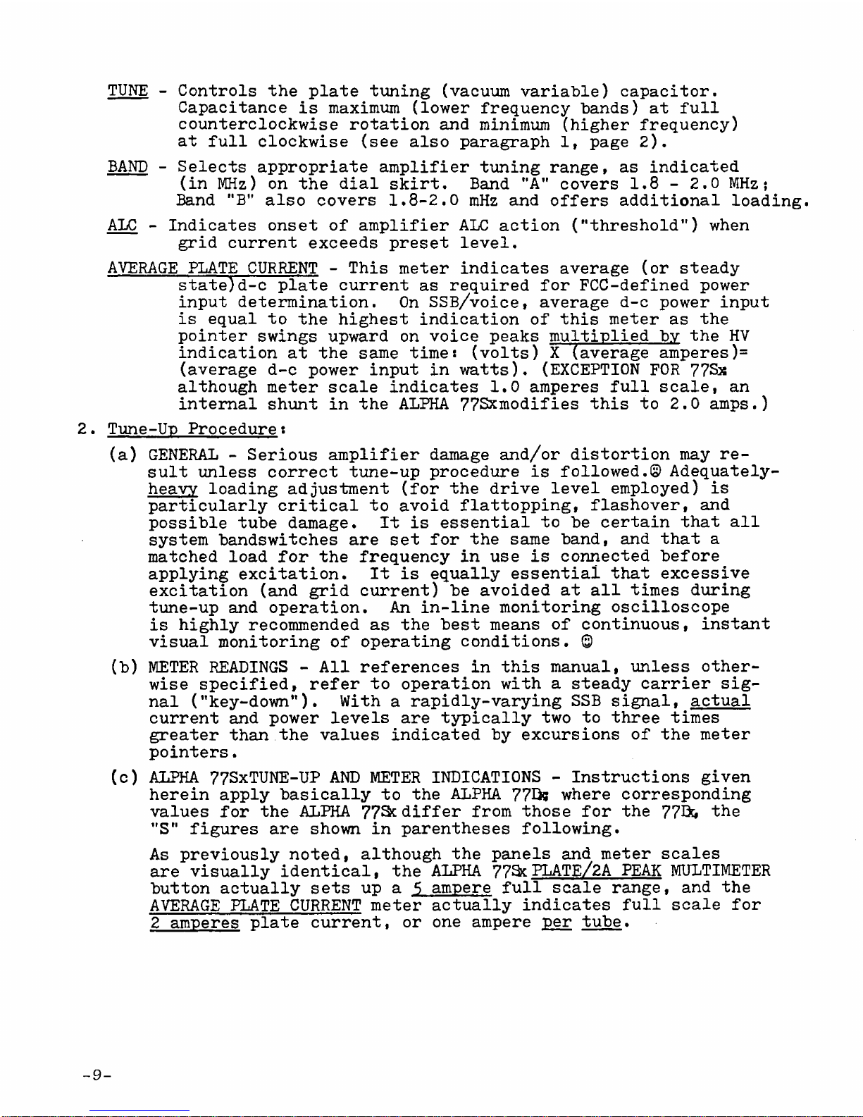
TUNE - C ntr ls the plate tuning (vacuum variable) capacit r.
Capacitance is maximum (l wer frequency bands) at full
c untercl ckwise r tati n and minimum (higher frequency)
at full cl ckwise (see als paragraph 1, page 2).
Selects appr priate amplifier tuning range, as indicated
(in MHz) n the dial skirt. Band "A" c vers 1.8 - 2.0 MHz;
Band "B" als c vers 1.8-2.0 mHz and ffers additi nal l ading.
Indicates nset f amplifier ALC acti n ("thresh ld") when
grid current exceeds preset level.
AVERAGE PLATE CURRENT - This meter indicates average ( r steady
state)d-c plate current as required f r FCC-defined p wer
input determinati n. On SSB/v ice, average d-c p wer input
is equal t the highest indicati n f this meter as the
p inter swings upward n v ice peaks multiplied by the HV
indicati n at the same timet (v lts) X (average amperes)=
(average d-c p wer input in watts). (EXCEPTION FOR 77Sx
alth ugh meter scale indicates 1.0 amperes full scale, an
internal shunt in the ALPHA 77Sxm difies this t 2.0 amps.)
2. Tune-Up Pr cedure:
(a) GENERAL - Seri us amplifier damage and/ r dist rti n may re
sult unless c rrect tune-up pr cedure is f ll wed.© Adequately-
heavy l ading adjustment (f r the drive level empl yed) is
particularly critical t av id flatt pping, flash ver, and
p ssible tube damage. It is essential t be certain that all
system bandswitches are set f r the same band, and that a
matched l ad f r the frequency in use is c nnected bef re
applying excitati n. It is equally essential that excessive
excitati n (and grid current) be av ided at all times during
tune-up and perati n. An in-line m nit ring scill sc pe
is highly rec mmended as the best means f c ntinu us, instant
visual m nit ring f perating c nditi ns. ©
(b) METER READINGS - All references in this manual, unless ther
wise specified, refer t perati n with a steady carrier sig
nal ("key-d wn"). With a rapidly-varying SSB signal, actual
current and p wer levels are typically tw t three times
greater than the values indicated by excursi ns f the meter
p inters.
(c) ALPHA 77SxTUNE-UP AND METER INDICATIONS - Instructi ns given
herein apply basically t the ALPHA 770? where c rresp nding
values f r the ALPHA 77Scdiffer fr m th se f r the 77B& the
"S" figures are sh wn in parentheses f ll wing.
As previ usly n ted, alth ugh the panels and meter scales
are visually identical, the ALPHA 77S?cPLATE/2A PEAK MULTIMETER
butt n actually sets up a 5 ampere full scale range, and the
AVERAGE PLATE CURRENT meter actually indicates full scale f r
2 amperes plate current, r ne ampere per tube.
BAND -
ALC -
-9-
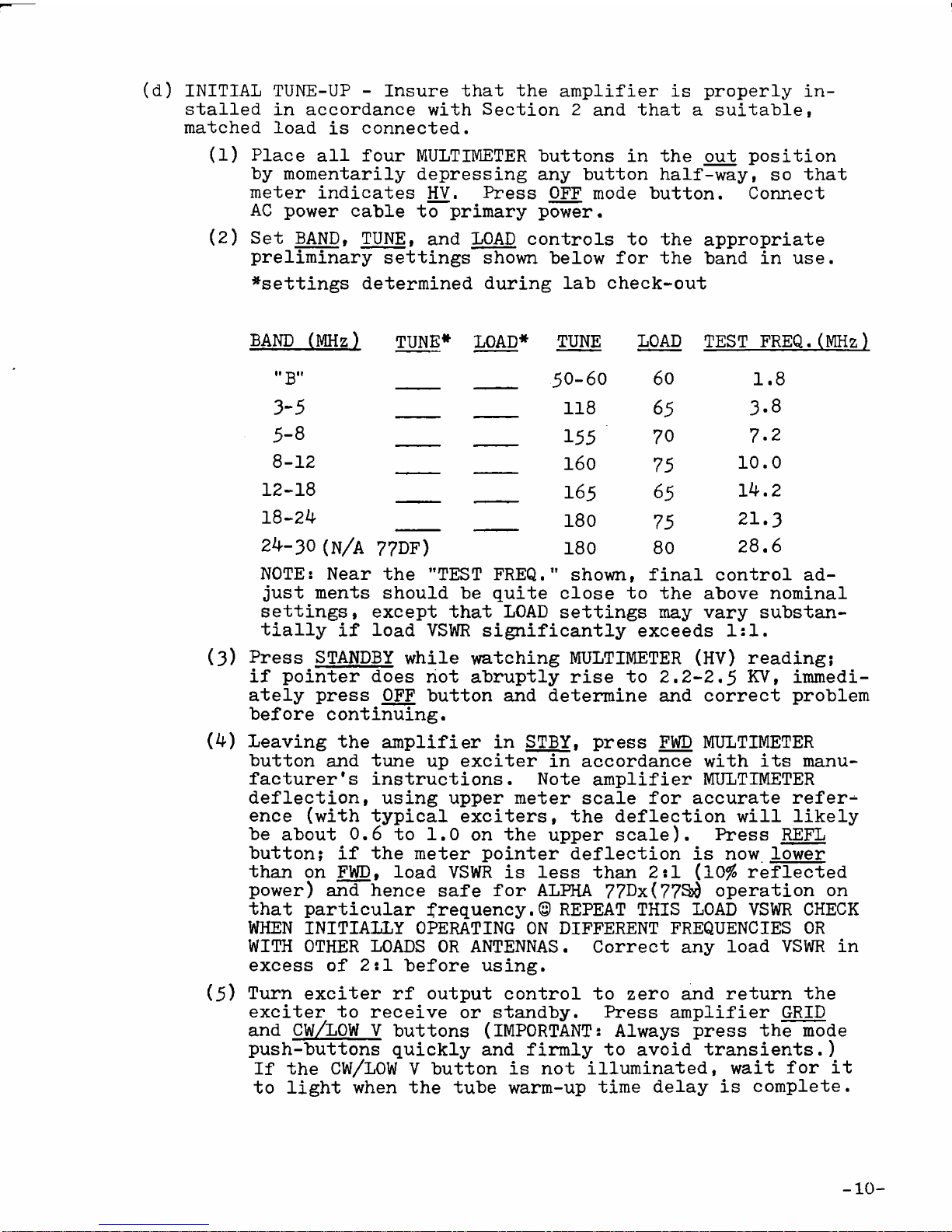
(d) INITIAL TUNE-UP - Insure that the amplifier is pr perly in
stalled in acc rdance with Secti n 2 and that a suitable,
matched l ad is c nnected.
(1) Place all f ur MULTIMETER butt ns in the ut p siti n
by m mentarily depressing any butt n half-way, s that
meter indicates HV. Press OFF m de butt n. C nnect
AC p wer cable t primary p wer.
(2) Set BAND» TUNE, and LOAD c ntr ls t the appr priate
preliminary settings sh wn bel w f r the band in use.
^settings determined during lab check- ut
BAND (MHz) TUNE* LOAD* TUNE LOAD TEST FREQ.(MHz)
"B" 50-60 60 1.8
3-5 118 65 3.8
5-8 155 70 7.2
8-12 160 75 10.0
12-18 165 65 i4.2
18-24 180 75 21.3
24-30(n/A 77DF) 180 80 28.6
NOTE: Near the "TEST FREQ." sh wn, final c ntr l ad
just ments sh uld be quite cl se t the ab ve n minal
settings, except that LOAD settings may vary substan
tially if l ad VSWR significantly exceeds 1:1.
(3) Press STANDBY while watching MULTIMETER (HV) reading;
if p inter d es n t abruptly rise t 2.2-2,5 KV, immedi
ately press OFF butt n and determine and c rrect pr blem
bef re c ntinuing.
(4) Leaving the amplifier in STBY. press FWD MULTIMETER
butt n and tune up exciter in acc rdance with its manu
facturer's instructi ns. N te amplifier MULTIMETER
deflecti n, using upper meter scale f r accurate refers
ence {with typical exciters, the deflecti n will likely
be ab ut 0.6 t 1.0 n the upper scale). Press REFL
butt n; if the meter p inter deflecti n is n w l wer
than n FWD# l ad VSWR is less than 2 si (10# reflected
p wer) and hence safe f r ALPHA 77Dx(77Sd perati n n
that particular frequency.© REPEAT THIS LOAD VSWR CHECK
WHEN INITIALLY OPERATING ON DIFFERENT FREQUENCIES OR
WITH OTHER LOADS OR ANTENNAS. C rrect any l ad VSWR in
excess f 2si bef re using.
(5) Turn exciter rf utput c ntr l t zer and return the
exciter t receive r standby. Press amplifier GRID
and CW/LOW V butt ns (IMPORTANT: Always press the m de
push-butt ns quickly and firmly t av id transients.)
If the CW/LOW V butt n is n t illuminated, wait f r it
t light when the tube warm-up time delay is c mplete.
-10

%\
IF AT ANY POINT IN THE FOLLOWING PROCEDURES THE AMPLIFIER
DOES NOT RESPOND AS EXPECTED, REMOVE EXCITATION IMMEDI
ATELY AND CORRECT THE PROBLEM BEFORE CONTINUING!
(6) Switch exciter t "tune” r "l ck key" c nditi n and
very sl wly increase its utput while watching the
amplifier GRID and PLATE meter indicati ns. B th
sh uld rise ff zer with a very l w level f rf exci
tati n (less than a watt). Sl wly increase excitati n
until plate current r grid current indicati n reaches
ab ut mid-scale.
(?) Press FWD butt n, Carefully adjust first LOAD. then
TUNE c ntr ls f r maximum indicati n f FWD rf p wer;
repeat until n further increase in p wer is achievable.
(8) Press GRID butt n and n te indicati ns f b th meters.
Desired values f r initial tune-up are GRID 0.15 ampere
(7?Sx - 0.3 ampere) and PLATE 0.45 amp f r 77DF (1 KW
d-c input @ 2200 typical plate v lts f r nominal U.S.
amateur input p wer), PLATE 0.6 t 0.7 amp f r 77Dx and
77Sx. If PLATE current is l wer than desired after
step (7)» slightly increase excitati n and repeat steps
(7)- and (8). If PLATE current is greater than desired,
slightly decrease excitati n and repeat (7) and (8).
(9) When the desired value f PLATE current exists after
c mpleti n f step (8), initial tune-up is c mplete.
(NOTE that plate current f 0,7 ampere @ appr ximately
2200 plate v lts f r g vernment/exp rt 77Dx and 77Sx
m dels, as suggested ab ve, c rresp nds t d-c plate
p wer inputs f appr ximately 1500 and 30°° watts, re
spectively ... since 77Sx actual plate current is twice
the meter indicati n as previ usly explained.)
3. Final Operati nal Adjustments and M nit rings
(a) KEYED CW, FSK/RTTY, SSTV, k# - At c mpleti n f* initial tune-
up as described ab ve, each m del is ready f r perati n in
any f these "carrier" m des at the p wer level f r which it
was tuned up. There are n restricti ns n "key d wn" time.
It is nly necessary t m nit r drive p wer adjustment s
that amplifier GRID current remains in the range f 0,1-0.15
ampere f r 77DF/77Dx versi ns and 0.2-0.3 ampere f r 77Sx.
(b) LOW POWER SSB/V0ICE - It is p ssible t perate the amplifier
n SSB/v ice at PEP p wer inputs appr ximately equal t the
d-c tune-up p wers given in (9) ab ve, by leaving the ampli
fier in its "CW" p siti n. Simply'switch the exciter t SSB
and speak n rmally int the mike while adjusting exciter rf
utput (usually with mike gain c ntr l) until highest swings
f the amplifier GRID current meter reach these levels:
77DF/77Dx - 50-100 mA (1/5 scale maximum)
77Sx - 100-200 mA (2/5 scale maximum)
AVERAGE d-c p wer input is the pr duct f highest PLATE meter
swings times plate v ltage (HV) meter indicati n at the same
m ment, and will typically be 35-50$ f the initial tune-up
input. PEP is ab ut equal t the initial tune-up p wer.
11
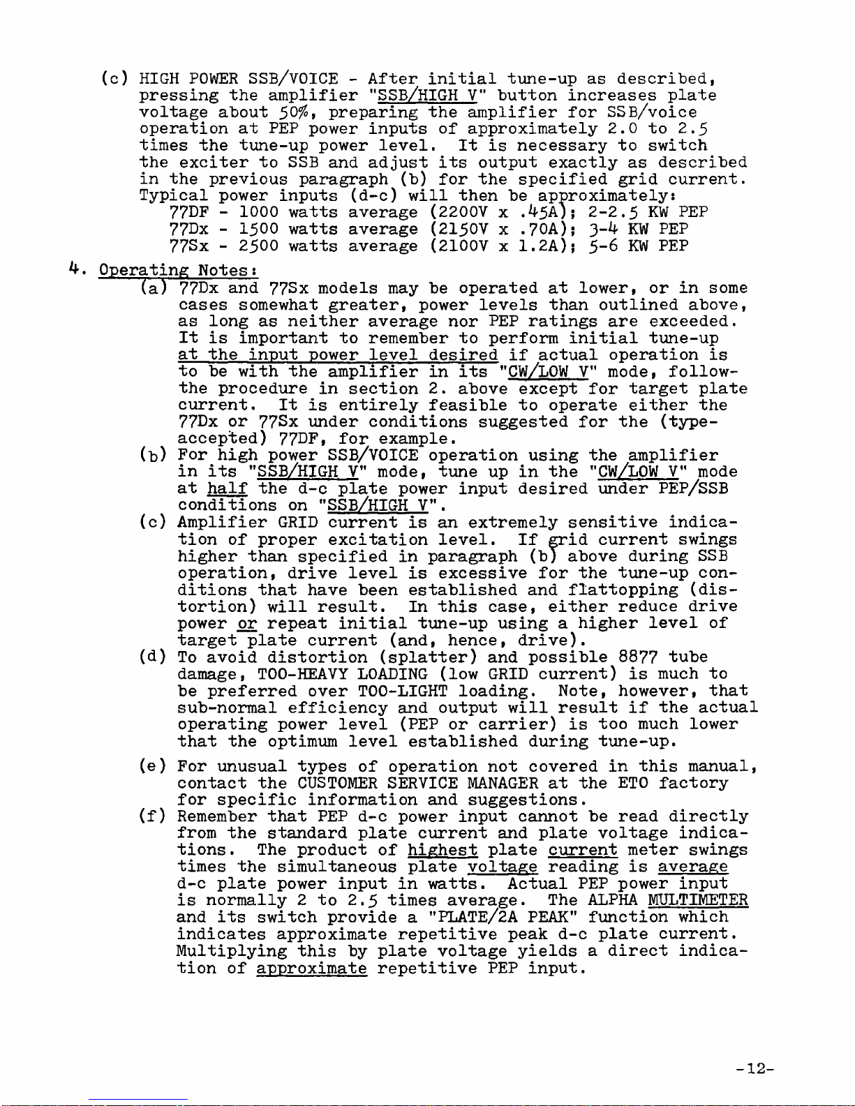
(c) HIGH POWER SSB/VOICE - After initial tune-up as described,
pressing the amplifier "5SB/HIGH V" butt n increases plate
v ltage ab ut 5°%> preparing the amplifier f r SSB/v ice
perati n at PEP p wer inputs f appr ximately 2.0 t 2.5
times the tune-up p wer level. It is necessary t switch
the exciter t SSB and adjust its utput exactly as described
in the previ us paragraph (b) f r the specified grid current.
Typical p wer inputs (d-c) will then be appr ximately:
77DF - 1000 watts average (2200V x .45A); 2-2.5 KW PEP
77Dx - 1500 watts average (2150V x .70A); 3-4 KW PEP
77Sx - 2500 watts average (2100V x 1.2A); 5-6 KW PEP
4. Operating N tes:
fa) 77Dx and 77Sx m dels may be perated at l wer, r in s me
cases s mewhat greater, p wer levels than utlined ab ve,
as l ng as neither average n r PEP ratings are exceeded.
It is imp rtant t remember t perf rm initial tune-up
at the input p wer level desired if actual perati n is
t be with the amplifier in its ”CW/LOW V" m de, f ll w-
the pr cedure in secti n 2. ab ve except f r target plate
current. It is entirely feasible t perate either the
77Dx r 77Sx under c nditi ns suggested f r the (type-
accepted) 77DF, f r example.
(■b) F r high p wer SSB/VOICE perati n using the amplifier
in its ”SSB/HIGH V” m de, tune up in the "CW/LOW V” m de
half the d-c plate p wer input desired under PEP/SSB
c nditi ns n "SSB/HIGH VM.
(c) Amplifier GRID current is an extremely sensitive indica
ti n f pr per excitati n level. If grid current swings
higher than specified in paragraph (b) ab ve during SSB
perati n, drive level is excessive f r the tune-up c n
diti ns that have been established and flatt pping (dis
t rti n) will result. In this case, either reduce drive
p wer r repeat initial tune-up using a higher level f
target plate current (and, hence, drive).
(d) T av id dist rti n (splatter) and p ssible 8877 tube
damage, T00-HEAVY LOADING (l w GRID current) is much t
be preferred ver TOO-LIGHT l ading. N te, h wever, that
sub-n rmal efficiency and utput will result if the actual
perating p wer level (PEP r carrier) is t much l wer
that the ptimum level established during tune-up.
(e) F r unusual types f perati n n t c vered in this manual,
c ntact the CUSTOMER SERVICE MANAGER at the ETO fact ry
f r specific inf rmati n and suggesti ns.
(f) Remember that PEP d-c p wer input cann t be read directly
fr m the standard plate current and plate v ltage indica
ti ns . The pr duct f highest plate current meter swings
times the simultane us plate v ltage reading is average
d-c plate p wer input in watts. Actual PEP p wer input
is n rmally 2 t 2.5 times average. The ALPHA MULTIMETER
and its switch pr vide a "PLATE/2A PEAK” functi n which
indicates appr ximate repetitive peak d-c plate current.
Multiplying this by plate v ltage yields a direct indica
ti n f appr ximate repetitive PEP input.
-12-

TUBE RATINGS - The 88?? is extremely rugged and perates with
a large safety margin if grid current is never all wed t
exceed 0.2 ampere, n r plate current 1.0 ampere, per tube.
Als , it is exceedingly imp rtant t insure that c ling air
fl w is never interrupted r bl cked. The inevitable c n
sequence f airfl w interrupti n during perati n is
destructi n f the tube.
INTERLOCKS - Y ur ALPHA is equipped with switches which shut
ff a-c p wer and sh rt the high v ltage p wer supply when
ever the cabinet t p c ver is pen. THESE PROTECTIVE
INTERLOCKS ARE PROVIDED FOR YOUR PROTECTION AGAINST POTEN
TIALLY FATAL ELECTRIC SHOCK RESULTING FROM CONTACT WITH
LETHAL VOLTAGES INSIDE THE AMPLIFIER. THE AMPLIFIER SHOULD
NEVER BE OPERATED WITH COVER REMOVED EXCEPT BY THOROUGHLY
KNOWLEDGABLE AND EXPERIENCED SERVICE PERSONNEL!
FUSES - Except in rare instances f c mp nent failure, the
bl wing f primary line fuses indicates either a severe and
sustained verdrive f the amplifier r a maj r p wer tran
sient. The latter may ccasi nally result fr m sl w r in
c mplete depressi n f a m de push butt n (STBY, CW, SSB),
resulting in irregular and abn rmal perati n f the main
and step-start p wer relays. Always press the butt ns firmly
and quickly t insure sm th change ver f functi n. The
internal step-start pr tecti n fuse may be bl wn by such a
switching transient, but applicati n f AC p wer while the
high v ltage cr wbar switch is sh rted (c ver pen), r by
vari us c mp nent failures.
NEVER REPLACE A BLOWN MAIN LINE FUSE WITH OTHER THAN A 250V
CERAMIC BODY FUSE OF THE TYPE (3AB r ABC) SUPPLIED, NOR OF
A GREATER CURRENT RATING THAN SPECIFIED (20 amperes ALPHA ??D*
25 amperes 177S:ji. The step-start fuse sh uld be replaced, if
necessary, with a similar sl w-bl w (type MDL r 3AG sl -bl )
unit f the riginal rating — 77D* 2 ampere; 77S* 3 ampere.
NEVER REPLACE A BLOWN FUSE UNTIL THE REASON FOR ITS BLOWING
HAS BEEN DETERMINED AND CORRECTED.
PLATE OVERCURRENT RELAY - This s len id functi ns primarily
t de-energize primary p wer quickly in the event f a fault
in the HV circuitry r gr ssly excessive drive c nditi ns.
Sh uld it trip, p pping " ut” all m de push-butt ns and shut
ting d wn the amplifier, it is essential t determine and c r
rect the cause bef re re-applying p wer by again depressing
ne f the m de butt ns.
MAINTENANCE AND TROUBLESHOOTING - M st apparent failures and
pr blems with the ALPHA 77Dxand 77Scresult fr m perat rs'
failure t read and th r ughly understand the c ntents f
this manual, as well as basic linear amplifier principles -
rather than fr m actual equipment defects.
M st actual equipment defects can be traced t pr blems with
tubes, fuses, l se c nnect rs r AC wiring externally, r
circuitry l cated n plug-in circuit b ard CB2.
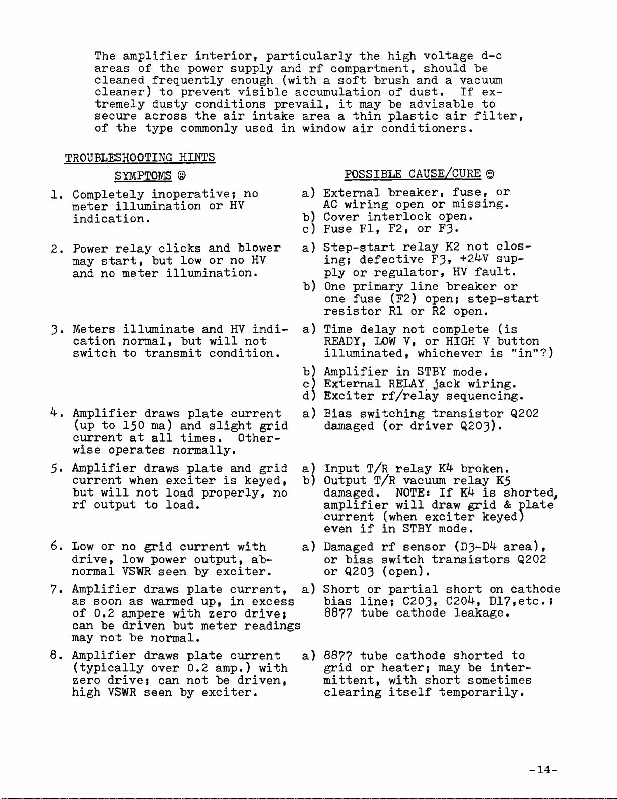
The amplifier interi r, particularly the high v ltage d-c
areas f the p wer supply and rf c mpartment, sh uld "be
cleaned frequently en ugh (with a s ft brush and a vacuum
cleaner) t prevent visible accumulati n f dust. If ex
tremely dusty c nditi ns prevail, it may be advisable t
secure acr ss the air intake area a thin plastic air filter,
f the type c mm nly used in wind w air c nditi ners.
TROUBLESHOOTING HINTS
SYMPTOMS ©
1, C mpletely in perative; n
meter illuminati n r HV
indicati n.
2. P wer relay clicks and bl wer
may start, but l w r n HV
and n meter illuminati n.
3- Meters illuminate and HV indi
cati n n rmal, but will n t
switch t transmit c nditi n.
4.
5.
6.
7.
8.
Amplifier draws plate current
(up t 150 ma) and slight grid
current at all times. Other
wise perates n rmally.
Amplifier draws plate and grid
current when exciter is keyed,
but will n t l ad pr perly, n
rf utput t l ad.
a)
b)
c)
a)
b)
a)
b)
c)
d)
a)
a)
b)
L w r n grid current with
drive, l w p wer utput, ab
n rmal VSWR seen by exciter.
Amplifier draws plate current,
as s n as warmed up, in excess
f 0.2 ampere with zer drive;
can be driven but meter readings
may n t be n rmal.
Amplifier draws plate current
(typically ver 0.2 amp.) with
zer drive; can n t be driven,
high VSWR seen by exciter.
a)
a)
a)
POSSIBLE CAUSE/CURE ©
External breaker, fuse, r
AC wiring pen r missing.
C ver interl ck pen.
Fuse FI, F2, r F3.
Step-start relay K2 n t cl s
ing; defective F3> +24V sup
ply r regulat r, HV fault.
One primary line breaker r
ne fuse (F2) pen; step-start
resist r R1 r R2 pen.
Time delay n t c mplete (is
READY, LOW V, r HIGH V butt n
illuminated, whichever is "in”?)
Amplifier in STBY m de.
External RELAY jack wiring.
Exciter rf/relay sequencing.
Bias switching transist r Q202
damaged ( r driver Q203).
Input T/R relay K4 br ken.
Output T/R vacuum relay K5
damaged. NOTE: If K4 is sh rted,
amplifier will draw grid & plate
current (when exciter keyed)
even if in STBY m de.
Damaged
r bias
r Q203
rf sens r (D3-D4 area),
switch transist rs Q202
( pen).
Sh rt r partial sh rt
bias line; C203» C204,
8877 tube cath de
n cath de
D17ietc.;
8877 tube cath de sh rted t
grid r heater; may be inter
mittent, with sh rt s metimes
clearing itself temp rarily.
-14-
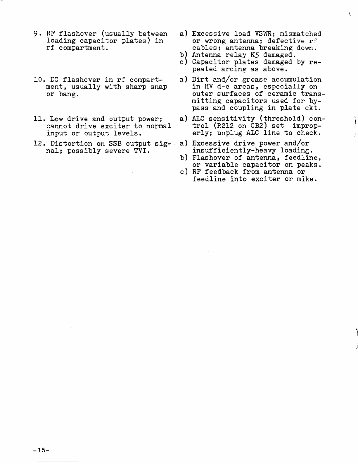
9. RF flash ver (usually between
l ading capacit r plates) in
rf c mpartment.
10. DC flash ver in rf c mpart
ment, usually with sharp snap
r bang.
11. L w drive and utput p wer;
cann t drive exciter t n rmal
input r utput levels.
12. Dist rti n n SSB utput sig
nal; p ssibly severe TVI.
-15-
a) Excessive l ad VSWR; mismatched
r wr ng antenna; defective rf
cables; antenna breaking d wn.
b) Antenna relay K5 damaged.
c) Capacit r plates damaged by re
peated arcing as ab ve.
a) Dirt and/ r grease accumulati n
in HV d-c areas, especially n
uter surfaces f ceramic trans
mitting capacit rs used f r by
pass and c upling in plate ckt.
a) ALC sensitivity (thresh ld) c n
tr l (R212 n CB2) set impr p
erly; unplug ALC line t check.
a) Excessive drive p wer and/ r
insufficiently-heavy l ading.
b) Flash ver f antenna, feedline,
r variable capacit r n peaks.
c) RF feedback fr m antenna r
feedline int exciter r mike.

SECTION 4
1. 8877 RF Amplifier Circuitry! (Refer t Fig. 18) The 8877 tri de
tube (tw , parallel-c nnected, in ALPHA 77S) is c nnected in
gr unded-grid f r high stability, linearity, and simplicity.
Bandswitch S2 and ass ciated c mp nents pr vide pre-tuned input
circuits t ptimize perf rmance n each amateur band fr m 160
thr ugh 15*f eters ( r ther frequency ranges if appr priately
readjusted). Switch SI permits disc nnecting the input tuning
netw rk f r perati n acr ss the amplifier^ entire tuning range
with ut input netw rk adjustments. (SI is l cated adjacent t
the tube s cket n the t p f the tube deck? m ve its butt n
t ward the rear f the chassis f r untuned input.) *10M 77Dx/Sx.
The utput (plate matching) netw rk is a full pi-L, pr viding
excellent harm nic suppressi n and perating efficiency acr ss
the entire tuning range. Use f a vacuum variable tuning capaci
t r c mbined with silver plated induct r L4, f heavy c pper
tubing, enhances efficiency n the highest frequency bands.
Multiply-insulated t r idal induct rs L5 and L7 maintain very
l w l sses c mbined with c mpactness and freed m fr m unwanted
cr ss-c upling n 3“5 MHz and 1.8-2.0 MHz. T r id L6 and
induct r L10 pr vide the necessary "L" inductance.
P wer reed relay K4 and vacuum relay K5 perf rm antenna change
ver switching at speeds sufficiently high t f ll w CW keying
at 50 WPM r m re, and perate silently. T r id Xil6 and ass ci
ated c mp nents c nstitute an rf wattmeter directi nal c upler.
Separate l w-level rf detect rs are pr vided, ne n either
side f input relay c ntacts K4, t pr vide c ntr l signals f r
perati n f the electr nic bias switch and QSK system. D1-D2
and related c mp nents are the "pre-K4M detect r and D3-D4 the
”p st-K4" detect r.
Als required f r perati n f the QSK system, the transmit (N.O.)
c ntacts f antenna relay K5 are is lated by rf ch kes LI 4 and
L15 plus feed-thru capacit r C30, t pr vide a d-c path at C3
which indicates cl sing f K5*s c ntacts. Series di des D5-D7
pr vide a leakage path t gr und via L14, pr tecting the "L"
netw rk and antenna circuitry against electr static charge
buildup r breakd wn f C20-C21; at the same time, the f rward
v ltage dr p f D5-D7 is sufficient t permit the QSK circuitry
t distinguish between the " pen" and "cl sed" states f K5-
2. P wer Supply and C ntr l: (Refer t Figs. 19 & 20) Main AC
p wer relay K1 perates ff rectified AC line v ltage, c ntr lled
by push butt n MODE switch S5 and c ver interl ck S9. Step-
start resist rs R1 and R2 limit the initial current inrush at
turn- n t 12 amperes maximum; as HV filter capacit r C reach
es full charge, all perating v ltages appr ach n rmal and step-
start relay K2 cl ses t sh rt ut R1 and R2. In the event f
a fault which prevents K2 fr m cl sing, step-start fuse F3 pr
tects R1 and R2 fr m damage. (F3 is l cated n the main chassis
immediately behind the p wer transf rmer and t the left f K3.)
THEORY OF OPERATION
16
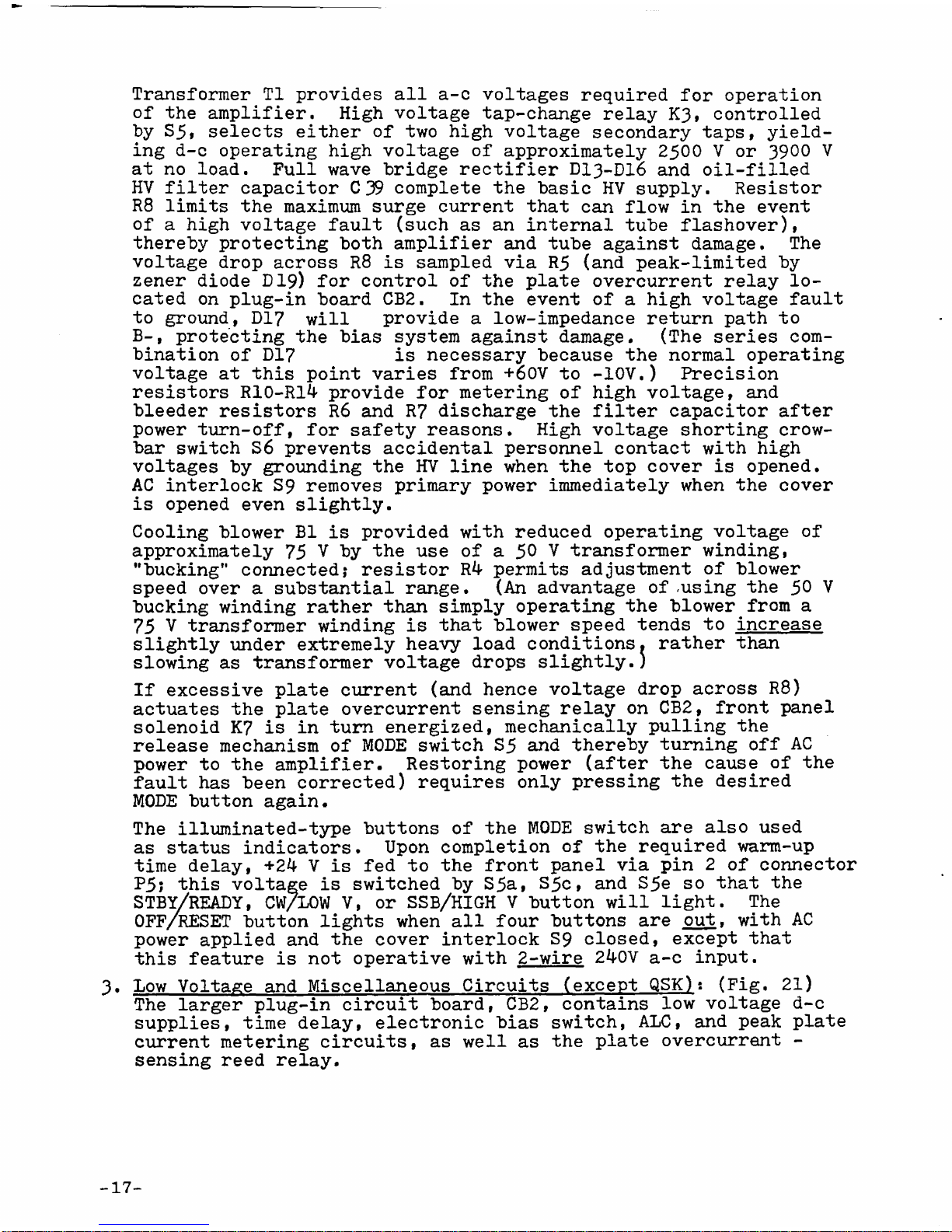
Transf rmer T1 pr vides all a-c v ltages required f r perati n
f the amplifier. High v ltage tap-change relay K3, c ntr lled
by S5, selects either f tw high v ltage sec ndary taps, yield
ing d-c perating high v ltage f appr ximately 2500 V r 3900 V
at n l ad. Full wave bridge rectifier DI3-DI6 and il-filled
HV filter capacit r C 39 c mplete the basic HV supply. Resist r
R8 limits the maximum surge current that can fl w in the event
f a high v ltage fault (such as an internal tube flash ver),
thereby pr tecting b th amplifier and tube against damage. The
v ltage dr p acr ss R8 is sampled via R5 (and peak-limited by
zener di de D19) f r c ntr l f the plate vercurrent relay l
cated n plug-in b ard CB2. In the event f a high v ltage fault
t gr und, D17 will pr vide a l w-impedance return path t
B-, pr tecting the bias system against damage. (The series c m
binati n f Dl? is necessary because the n rmal perating
v ltage at this p int varies fr m +60V t -10V.) Precisi n
resist rs R10-R14 pr vide f r metering f high v ltage, and
bleeder resist rs R6 and R7 discharge the filter capacit r after
p wer turn- ff, f r safety reas ns. High v ltage sh rting cr w
bar switch S6 prevents accidental pers nnel c ntact with high
v ltages by gr unding the HV line when the t p c ver is pened.
AC interl ck S9 rem ves primary p wer immediately when the c ver
is pened even slightly.
Cooling blo er B1 is provided ith reduced operating voltage of
approximately 75 V by the use of a 50 V transformer inding,
"bucking" connected; resistor R4 permits adjustment of blo er
speed over a substantial range. (An advantage of -using the 50 V
bucking inding rather than simply operating the blo er from a
75 V transformer inding is that blo er speed tends to increase
slightly under extremely heavy load conditions, rather than
slo ing as transformer voltage drops slightly.)
If excessive plate current (and hence v ltage dr p acr ss R8)
actuates the plate vercurrent sensing relay n CB2, fr nt panel
s len id K7 is in turn energized, mechanically pulling the
release mechanism f MODE switch S5 and thereby turning ff AC
p wer t the amplifier. Rest ring p wer (after the cause f the
fault has been c rrected) requires nly pressing the desired
MODE butt n again.
The illuminated-type butt ns f the MODE switch are als used
as status indicat rs. Up n c mpleti n f the required warm-up
time delay, +24 V is fed t the fr nt panel via pin 2 f c nnect r
P5; this v ltage is switched by S5a, S5c, and S5e s that the
STBY/READY, CW/LOW V, r SSB/HIGH V butt n will light. The
OFF/RESET butt n lights when all f ur butt ns are ut, with AC
p wer applied and the c ver interl ck S9 cl sed, except that
this feature is n t perative with 2-wire 240V a-c input.
3. L w V ltage and Miscellane us Circuits (except QSK)s (Fig. 21)
The larger plug-in circuit b ard, CB2, c ntains l w v ltage d-c
supplies, time delay, electr nic bias switch, ALC, and peak plate
current metering circuits, as well as the plate vercurrent -
sensing reed relay.
17
This manual suits for next models
1
Table of contents
Other EHRHORN Amplifier manuals


Popular Amplifier manuals by other brands


Incriminator Audio
Incriminator Audio IA6.4 owner's manual

Kollmorgen Seidel
Kollmorgen Seidel SERVOSTAR 600 Series Assembly, Installation and Commissioning Instructions

McIntosh
McIntosh C42 owner's manual

NUCLEAR DATA
NUCLEAR DATA ND509 instruction manual

Cadence
Cadence FXA Series owner's manual

Conrad-johnson design
Conrad-johnson design MV50 user manual


